AUX Ram 2500 2020 User Guide
[x] Cancel search | Manufacturer: RAM, Model Year: 2020, Model line: 2500, Model: Ram 2500 2020Pages: 553, PDF Size: 21.99 MB
Page 126 of 553
124GETTING TO KNOW YOUR INSTRUMENT PANEL
Transmission Temperature
Oil Life
Exhaust Brake — If Equipped
Turbo Boost — If Equipped
Fuel Filter Life — If Equipped
Lower Right — If Equipped
None
Compass
Outside Temp
Time
Range To Empty
Average MPG
Current MPG
Trip A Distance
Trip B Distance
Trailer Trip
Trailer Brake
Oil Pressure (Default Setting)
Coolant Temperature
Oil Temperature
Battery Voltage
Transmission Temperature
Oil Life
Exhaust Brake — If Equipped
Turbo Boost — If Equipped
Fuel Filter Life — If Equipped
Restore Defaults
Cancel (Default Setting)
Right Arrow Button
Commercial Settings — If Equipped
Commercial Settings allows the driver to set
and recall additional features when the trans-
mission is in PARK (P).
Push and release the up and down button until
Commercial Settings displays in the instrument
cluster display.
Follow the prompts to enter the required PIN
and enter the Commercial Settings submenu. Commercial Settings allows you to access the
following features (if equipped):
Backup Alarm
ParkSense
Aux Switches
PIN Setup
NOTE:
If the vehicle’s PIN is forgotten or not known,
see an authorized dealer to have the PIN reset.
Diesel Messages And Warnings — 6.7L
Cummins Diesel Engine
Diesel Particulate Filter (DPF) Messages
The Cummins diesel engine meets all diesel
emissions standards, resulting in one of the
lowest emitting diesel engines ever produced.
To achieve these emissions standards, your
vehicle is equipped with a state-of-the-art
engine and exhaust system. These systems are
seamlessly integrated into your vehicle and
managed by the Powertrain Control Module
(PCM). The PCM manages engine combustion
to allow the exhaust system’s catalyst to trap
and burn Particulate Matter (PM) pollutants,
with no input or interaction on your part.
20_DJD2_OM_EN_USC_t.book Page 124
Page 139 of 553
GETTING TO KNOW YOUR INSTRUMENT PANEL137
Service Forward Collision Warning (FCW)
Light — If Equipped
This warning light will illuminate to
indicate a fault in the Forward Colli-
sion Warning System. Contact an
authorized dealer for service.
Refer to "Forward Collision Warning (FCW)" in
"Safety" for further information.
Service 4WD Warning Light — If Equipped
This warning light will illuminate to
signal a fault with the 4WD system. If
the light stays on or comes on during
driving, it means that the 4WD system
is not functioning properly and that service is
required. We recommend you drive to the
nearest service center and have the vehicle
serviced immediately.
Speed Control Fault Warning Light
This warning light will illuminate to
indicate the Speed Control System is
not functioning properly and service is
required. Contact an authorized
dealer.
Sway Bar Fault Warning Light
This light will illuminate when there is
a fault in the sway bar disconnect
system.
Refer to “Stabilizer/Sway Bar System — Power
Wagon Only” in “Starting And Operating” for
further information.
Yellow Indicator Lights
Forward Collision Warning Off Indicator Light
— If Equipped
This indicator light illuminates to indi -
cate that Forward Collision Warning is
off.
Refer to “Auxiliary Driving Systems” in “Safety”
for further information.
Air Suspension Payload Protection Indicator
Light — If Equipped
This indicator light will illuminate to
indicate that the maximum payload
may have been exceeded or load
leveling cannot be achieved at its
current ride height. Protection Mode will auto -
matically be selected in order to “protect” the air suspension system, air suspension adjust
-
ment is limited due to payload.
TOW/HAUL Indicator Light
This indicator light will illuminate
when TOW/HAUL mode is selected.
Refer to “Trailer Towing” in “Starting
And Operating” for further informa -
tion.
Cargo Light — If Equipped
This indicator light will illuminate
when the cargo light is activated by
pushing the cargo light button on the
headlight switch.
Cold Ambient Derate Mode Indicator Light —
If Equipped
This indicator light will illuminate
when a derate (engine power reduc -
tion) is activated for protection of the
turbocharger in cold ambient
temperatures.
For further information, refer to “Instrument
Cluster Display” in “Getting To Know Your
Instrument Panel”.
3
20_DJD2_OM_EN_USC_t.book Page 137
Page 155 of 553
SAFETY153
Traction Control System (TCS)
This system monitors the amount of wheel spin
of each of the driven wheels. If wheel spin is
detected, the Traction Control System (TCS)
may apply brake pressure to the spinning
wheel(s) and/or reduce engine power to provide
enhanced acceleration and stability. A feature
of the TCS, Brake Limited Differential (BLD),
functions similar to a limited slip differential
and controls the wheel spin across a driven
axle. If one wheel on a driven axle is spinning
faster than the other, the system will apply the
brake of the spinning wheel. This will allow more
engine power to be applied to the wheel that is
not spinning. BLD may remain enabled even if
TCS and Electronic Stability Control (ESC) are in
a reduced mode.
Trailer Sway Control (TSC)
Trailer Sway Control (TSC) uses sensors in the
vehicle to recognize an excessively swaying
trailer and will take the appropriate actions to
attempt to stop the sway. TSC will become
active automatically once an excessively
swaying trailer is recognized. NOTE:
TSC cannot stop all trailers from swaying.
Always use caution when towing a trailer and
follow the trailer tongue weight recommenda
-
tions. Refer to “Trailer Towing” in “Starting And
Operating” for further information.
When TSC is functioning, the “ESC Activation/
Malfunction Indicator Light” will flash, the
engine power may be reduced and you may feel
the brakes being applied to individual wheels to
attempt to stop the trailer from swaying. TSC is
disabled when the ESC system is in the “Partial
Off” or “Full Off” modes.
AUXILIARY DRIVING SYSTEMS
Blind Spot Monitoring (BSM) — If Equipped
The Blind Spot Monitoring (BSM) system uses
two radar-based sensors, located inside the tail -
lights, to detect highway licensable vehicles
(automobiles, trucks, motorcycles, etc.) that enter the blind spot zones from the rear/front/
side of the vehicle.
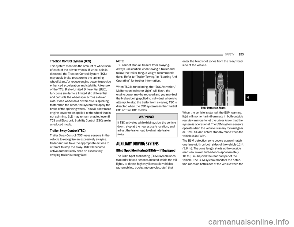
Rear Detection Zones
When the vehicle is started, the BSM warning
light will momentarily illuminate in both outside
rearview mirrors to let the driver know that the
system is operational. The BSM system sensors
operate when the vehicle is in any forward gear
or REVERSE and enters standby mode when the
vehicle is in PARK.
The BSM detection zone covers approximately
one lane width on both sides of the vehicle 12 ft
(3.8 m). The zone length starts at the outside
rear view mirror and extends approximately
10 ft (3 m) beyond the rear bumper of the
vehicle. The BSM system monitors the detec -
tion zones on both sides of the vehicle when the
WARNING!
If TSC activates while driving, slow the vehicle
down, stop at the nearest safe location, and
adjust the trailer load to eliminate trailer
sway.
4
20_DJD2_OM_EN_USC_t.book Page 153
Page 162 of 553
160SAFETY
Le présent appareil est conforme aux CNR
d`Innovation, Science and Economic Develop -
ment applicables aux appareils radio exempts
de licence. L'exploitation est autorisée aux deux
conditions suivantes:
1. l'appareil ne doit pas produire de brouil -
lage, et
2. l'utilisateur de l'appareil doit accepter tout brouillage radioélectrique subi, même si le
brouillage est susceptible d'en comprom -
ettre le fonctionnement.
La operación de este equipo está sujeta a las
siguientes dos condiciones:
1. es posible que este equipo o dispositivo no cause interferencia perjudicial y
2. este equipo o dispositivo debe aceptar cual -
quier interferencia, incluyendo la que
pueda causar su operación no deseada.
NOTE:
Changes or modifications not expressly
approved by the party responsible for compli -
ance could void the user’s authority to operate
the equipment.Forward Collision Warning (FCW) With
Mitigation — If Equipped
The Forward Collision Warning (FCW) system
provides the driver with audible, visual warnings
(within the instrument cluster display), and may
apply a haptic warning in the form of a brake
jerk, to warn the driver when it detects a poten -
tial frontal collision. The warnings are intended
to provide the driver with enough time to react,
avoid or mitigate the potential collision.
NOTE:
FCW monitors the information from the forward
looking sensors as well as Electronic Brake
Controller (EBC), to calculate the probability of a
forward collision. When the system determines
that a forward collision is probable, the driver
will be provided with audible and visual warn-
ings as well as a possible haptic warning in the
form of a brake jerk.
If the driver does not take action based upon
these progressive warnings, then the system
will provide a limited level of active braking to
help slow the vehicle and mitigate the potential
forward collision. If the driver reacts to the warn -
ings by braking and the system determines that
the driver intends to avoid the collision by
braking but has not applied sufficient brake force, the system will compensate and provide
additional brake force as required. When towing
a trailer, the system will also respond to activate
the trailer brakes (if equipped).
If a FCW with Mitigation event begins at a speed
below 32 mph (52 km/h), the system may
provide the maximum braking possible to miti
-
gate the potential forward collision. If the
Forward Collision Warning with Mitigation event
stops the vehicle completely, the system will
hold the vehicle at standstill for two seconds
and then release the brakes.
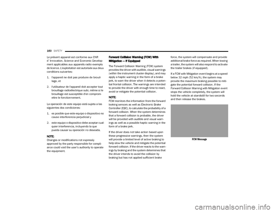
FCW Message
20_DJD2_OM_EN_USC_t.book Page 160
Page 165 of 553
SAFETY163
Le présent appareil est conforme aux CNR
d`Innovation, Science and Economic Develop -
ment applicables aux appareils radio exempts
de licence. L'exploitation est autorisée aux deux
conditions suivantes:
1. l'appareil ne doit pas produire de brouil -
lage, et
2. l'utilisateur de l'appareil doit accepter tout brouillage radioélectrique subi, même si le
brouillage est susceptible d'en comprom -
ettre le fonctionnement.
La operación de este equipo está sujeta a las
siguientes dos condiciones:
1. es posible que este equipo o dispositivo no cause interferencia perjudicial y
2. este equipo o dispositivo debe aceptar cual -
quier interferencia, incluyendo la que
pueda causar su operación no deseada.
NOTE:
Changes or modifications not expressly
approved by the party responsible for compli -
ance could void the user’s authority to operate
the equipment.Tire Pressure Monitoring System (TPMS)
The Tire Pressure Monitoring System (TPMS)
will warn the driver of a low tire pressure based
on the vehicle recommended cold placard pres -
sure.
NOTE:
The TPMS Warning Light will illuminate in the
instrument cluster and a chime will sound when
tire pressure is low in one or more of the four
active road tires. In addition, the instrument
cluster will display a graphic showing the pres -
sure values of each tire with the low tire pres -
sure values in a different color, or the Uconnect
radio will display a TPMS message, when this
occurs you must increase the tire pressure to
the recommended cold placard pressure in
order for the TPMS Warning Light to turn off.
The tire pressure will vary with temperature by
about 1 psi (7 kPa) for every 12°F (6.5°C). This
means that when the outside temperature
decreases, the tire pressure will decrease. Tire
pressure should always be set based on cold
inflation tire pressure. This is defined as the tire
pressure after the vehicle has not been driven
for at least three hours, or driven less than
1 mile (1.6 km) after a three hour period. The
cold tire inflation pressure must not exceed the maximum inflation pressure molded into the
tire sidewall. Refer to “Tires” in “Servicing And
Maintenance” for information on how to prop
-
erly inflate the vehicle’s tires. The tire pressure
will also increase as the vehicle is driven - this is
normal and there should be no adjustment for
this increased pressure.
The TPMS will warn the driver of a low tire pres -
sure if the tire pressure falls below the low-pres -
sure warning limit for any reason, including low
temperature effects and natural pressure loss
through the tire.
The TPMS will continue to warn the driver of low
tire pressure as long as the condition exists,
and will not turn off until the tire pressure is at
or above the recommended cold placard pres -
sure. Once the low TPMS Warning Light illumi -
nates, you must increase the tire pressure to
the recommended cold placard pressure in
order for the TPMS Warning Light to turn off. The
system will automatically update and the TPMS
Warning Light will turn off once the system
receives the updated tire pressures. The vehicle
may need to be driven for up to 20 minutes
above 15 mph (24 km/h) in order for the TPMS to receive this information.
4
20_DJD2_OM_EN_USC_t.book Page 163
Page 173 of 553

SAFETY171
displayed, and a pressure value will display in
place of the dashes. A system fault can occur
due to any of the following:
Signal interference due to electronic devices
or driving next to facilities emitting the same
radio frequencies as the TPM sensors.
Installing aftermarket window tinting that
contains materials that may block radio wave
signals.
Accumulation of snow or ice around the
wheels or wheel housings.
Using tire chains on the vehicle.
Using wheels/tires not equipped with TPM
sensors.
General Information
The following regulatory statement applies to all
Radio Frequency (RF) devices equipped in this
vehicle:
This device complies with Part 15 of the FCC
Rules and with Innovation, Science and
Economic Development Canada license-exempt
RSS standard(s). Operation is subject to the
following two conditions:
1. This device may not cause harmful interfer
-
ence, and
2. This device must accept any interference received, including interference that may
cause undesired operation.
Le présent appareil est conforme aux CNR
d`Innovation, Science and Economic Develop -
ment applicables aux appareils radio exempts
de licence. L'exploitation est autorisée aux deux
conditions suivantes:
1. l'appareil ne doit pas produire de brouil -
lage, et
2. l'utilisateur de l'appareil doit accepter tout brouillage radioélectrique subi, même si le
brouillage est susceptible d'en comprom -
ettre le fonctionnement.
La operación de este equipo está sujeta a las
siguientes dos condiciones:
1. es posible que este equipo o dispositivo no cause interferencia perjudicial y
2. este equipo o dispositivo debe aceptar cual -
quier interferencia, incluyendo la que
pueda causar su operación no deseada. NOTE:
Changes or modifications not expressly
approved by the party responsible for compli
-
ance could void the user’s authority to operate
the equipment.
OCCUPANT RESTRAINT SYSTEMS
Some of the most important safety features in
your vehicle are the restraint systems:
Occupant Restraint Systems Features
Seat Belt Systems
Supplemental Restraint Systems (SRS) Air
Bags
Child Restraints
Some of the safety features described in this
section may be standard equipment on some
models, or may be optional equipment on
others. If you are not sure, ask an authorized
dealer.
Important Safety Precautions
Please pay close attention to the information in
this section. It tells you how to use your restraint
system properly, to keep you and your passen -
gers as safe as possible.
4
20_DJD2_OM_EN_USC_t.book Page 171
Page 245 of 553
STARTING AND OPERATING243
Torque Converter Clutch
A feature designed to improve fuel economy
has been included in the automatic transmis -
sion on your vehicle. A clutch within the torque
converter engages automatically at calibrated
speeds. This may result in a slightly different
feeling or response during normal operation in
the upper gears. When the vehicle speed drops
or during some accelerations, the clutch auto -
matically disengages.
NOTE:
The torque converter clutch will not engage,
until the transmission fluid and engine
coolant are warm [usually after 1 to 3 miles
(2 to 5 km) of driving]. Because engine speed
is higher when the torque converter clutch is
not engaged, it may seem as if the transmis -
sion is not shifting properly when cold. This is normal. Using the Electronic Range Select
(ERS) shift control, when the transmission is
sufficiently warm, will demonstrate that the
transmission is able to shift into and out of
Overdrive.
If the vehicle has not been driven for several
days, the first few seconds of operation after
shifting the transmission into gear may seem
sluggish. This is due to the fluid partially
draining from the torque converter into the
transmission. This condition is normal and
will not cause damage to the transmission.
The torque converter will refill within five
seconds after starting the engine.
AUXILIARY SWITCHES — IF EQUIPPED
There can be up to six auxiliary switches located
in the lower switch bank of the instrument panel
which can be used to power various electronic
devices and PTO (Power Take Off) – If Equipped.
If Power Take Off is equipped, it will take the
place of the sixth Auxiliary switch. Connections
to the switches are found under the hood in the
connectors attached to the auxiliary Power
Distribution Center.
You have the ability to configure the function
-
ality of the auxiliary switches via the instrument cluster display. All switches can now be config
-
ured for setting the switch type operation to
latching or momentary, power source of either
battery or ignition, and ability to hold last state
across key cycles.
NOTE:
Holding last state conditions are met when
switch type is set to latching and power source
is set to ignition.
For further information on using the auxiliary
switches, please refer to the Ram Body Builders
Guide by accessing www.rambodybuilder.com
and choosing the appropriate links.
ACTIVE NOISE CANCELLATION
Your vehicle is equipped with an Active Noise
Cancellation system that cannot be turned off.
This system is designed to address exhaust and
engine noise. The system relies on four micro -
phones embedded in the headliner, which
monitor exhaust and engine noise, and assists
an onboard frequency generator, which creates
counteracting sound waves in the audio
system’s speakers. This helps keep the vehicle
quiet at idle and during drive. The system is
deactivated when the windows are rolled down.
WARNING!
Do not use the “TOW/HAUL” feature when
driving in icy or slippery conditions. The
increased engine braking can cause the rear
wheels to slide, and the vehicle to swing
around with the possible loss of vehicle
control, which may cause an accident
possibly resulting in personal injury or death.
5
20_DJD2_OM_EN_USC_t.book Page 243
Page 289 of 553
STARTING AND OPERATING287
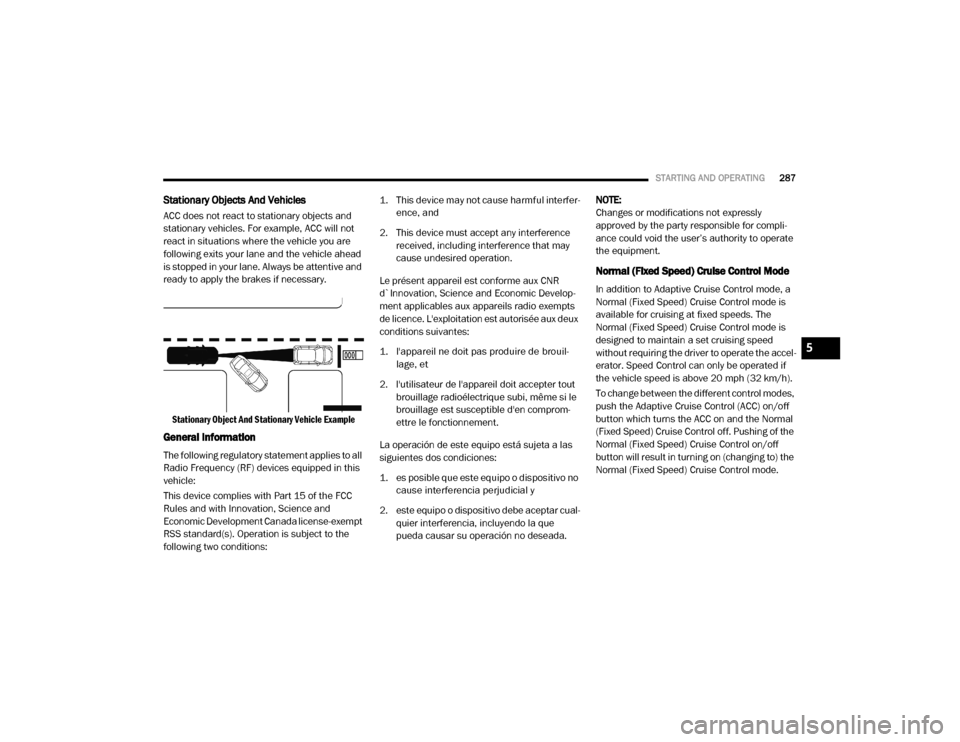
Stationary Objects And Vehicles
ACC does not react to stationary objects and
stationary vehicles. For example, ACC will not
react in situations where the vehicle you are
following exits your lane and the vehicle ahead
is stopped in your lane. Always be attentive and
ready to apply the brakes if necessary.
Stationary Object And Stationary Vehicle Example
General Information
The following regulatory statement applies to all
Radio Frequency (RF) devices equipped in this
vehicle:
This device complies with Part 15 of the FCC
Rules and with Innovation, Science and
Economic Development Canada license-exempt
RSS standard(s). Operation is subject to the
following two conditions:
1. This device may not cause harmful interfer
-
ence, and
2. This device must accept any interference received, including interference that may
cause undesired operation.
Le présent appareil est conforme aux CNR
d`Innovation, Science and Economic Develop -
ment applicables aux appareils radio exempts
de licence. L'exploitation est autorisée aux deux
conditions suivantes:
1. l'appareil ne doit pas produire de brouil -
lage, et
2. l'utilisateur de l'appareil doit accepter tout brouillage radioélectrique subi, même si le
brouillage est susceptible d'en comprom -
ettre le fonctionnement.
La operación de este equipo está sujeta a las
siguientes dos condiciones:
1. es posible que este equipo o dispositivo no cause interferencia perjudicial y
2. este equipo o dispositivo debe aceptar cual -
quier interferencia, incluyendo la que
pueda causar su operación no deseada. NOTE:
Changes or modifications not expressly
approved by the party responsible for compli
-
ance could void the user’s authority to operate
the equipment.
Normal (Fixed Speed) Cruise Control Mode
In addition to Adaptive Cruise Control mode, a
Normal (Fixed Speed) Cruise Control mode is
available for cruising at fixed speeds. The
Normal (Fixed Speed) Cruise Control mode is
designed to maintain a set cruising speed
without requiring the driver to operate the accel -
erator. Speed Control can only be operated if
the vehicle speed is above 20 mph (32 km/h).
To change between the different control modes,
push the Adaptive Cruise Control (ACC) on/off
button which turns the ACC on and the Normal
(Fixed Speed) Cruise Control off. Pushing of the
Normal (Fixed Speed) Cruise Control on/off
button will result in turning on (changing to) the
Normal (Fixed Speed) Cruise Control mode.
5
20_DJD2_OM_EN_USC_t.book Page 287
Page 305 of 553
STARTING AND OPERATING303
image will continue to be displayed until the
display timer exceeds 10 seconds.
NOTE:
If the vehicle speed remains below 8 mph
(13 km/h), the Rear View Camera image will
be displayed continuously until deactivated
via the touchscreen button "X", the transmis -
sion is shifted into PARK, or the ignition is
placed in the OFF position.
The touchscreen button "X" to disable display
of the camera image is made available ONLY
when the vehicle is not in REVERSE.
Cargo Camera Icons — If Equipped Backup Camera Touchscreen Button
Cargo Camera Touchscreen Button
AUX Camera Touchscreen Button
If equipped with a Cargo Camera, a touchscreen
button to indicate the current active Camera
image being displayed is made available when -
ever the Rear View Camera image is displayed. If equipped with a Cargo Camera, a touchscreen
button to switch the display to Cargo Camera
image is made available whenever the Rear
View Camera image is displayed.
A touchscreen button "X" to disable display of
the camera image is made available when the
vehicle is not in REVERSE gear.
When enabled, active guidelines are overlaid on
the backup camera image to illustrate the width
of the vehicle and its projected backup path
based on the steering wheel position. The active
guidelines will show separate zones that will
help indicate the distance to the rear of the
vehicle.
NOTE:
For further information about how to access
and change the programmable features of the
ParkView Rear Backup Camera, refer to “Ucon
-
nect Settings” in “Multimedia.”
A dashed center line overlay indicates the
center of the vehicle to assist with parking or
aligning to a hitch/receiver. The following table
shows the approximate distances for each
zone:
Zones Distance To The Rear
Of The Vehicle
Red 0 - 1 ft (0 - 30 cm)
Yellow 1 ft - 6.5 ft
(30 cm - 2m)
Green 6.5 ft or greater
(2 m or greater)
WARNING!
Drivers must be careful when backing up
even when using the ParkView Rear Back Up
Camera. Always check carefully behind your
vehicle, and be sure to check for pedestrians,
animals, other vehicles, obstructions, or blind
spots before backing up. You are responsible
for the safety of your surroundings and must
continue to pay attention while backing up.
Failure to do so can result in serious injury or
death.5
20_DJD2_OM_EN_USC_t.book Page 303
Page 306 of 553
304STARTING AND OPERATING
The ParkView Camera is located in the center of
the tailgate handle.
NOTE:
If snow, ice, mud, or any foreign substance
builds up on the camera lens, clean the lens,
rinse with water, and dry with a soft cloth. Do
not cover the lens.
Zoom View
When the Rear View Camera image is
being displayed, and the vehicle
speed is below 8 mph (13 km/h)
while in any gear selector position,
Zoom View is available. By pressing the “magni -
fying glass” icon in the upper left of the display screen, the image will zoom in to four times the
standard view. Pressing the icon a second time
will return the view to the standard Backup
Camera display.
When Zoom View is selected while the vehicle is
in REVERSE, then shifted to DRIVE, the camera
delay view will display the standard Backup
Camera view. If the vehicle is then returned to
REVERSE gear from DRIVE, the Zoom View
selection will automatically resume.
Shifting to NEUTRAL from any gear will maintain
the selected view (Zoom or Standard) as long as
the vehicle is below 8 mph (13 km/h).
If the vehicle is in PARK, Zoom View is available
until the gear selector is placed in DRIVE or
REVERSE.
NOTE:
If the vehicle is in DRIVE, NEUTRAL, or
REVERSE, and speed is greater than or equal
to 8 mph (13 km/h), Zoom View is unavail
-
able and the icon will appear gray.
While in Zoom View, the guidelines will not be
visible.
AUX Camera — If Equipped
Your vehicle may be equipped with one or two
AUX Cameras, which display rearview and side
view images from the trailer on the touch-
screen.
Activation
The AUX Camera is activated by first pressing
the Backup Camera, Cargo Camera (if
equipped), or Surround View Camera (if
equipped) button on the touchscreen, followed
by the AUX button located in the upper left
corner of the rearview display. The AUX camera
can also be activated when the vehicle is in
REVERSE by pressing the AUX button.
If equipped with two AUX Cameras, you can
switch between each camera by then pressing
the AUX1 or AUX2 buttons on the Trailer Camera
display.
AUX1 Camera Button
AUX2 Camera ButtonCAUTION!
To avoid vehicle damage, ParkView should
only be used as a parking aid. The ParkView
camera is unable to view every obstacle or
object in your drive path.
To avoid vehicle damage, the vehicle must
be driven slowly when using ParkView to be
able to stop in time when an obstacle is
seen. It is recommended that the driver
look frequently over his/her shoulder when
using ParkView.
20_DJD2_OM_EN_USC_t.book Page 304