display Ram 2500 2020 Owner's Guide
[x] Cancel search | Manufacturer: RAM, Model Year: 2020, Model line: 2500, Model: Ram 2500 2020Pages: 553, PDF Size: 21.99 MB
Page 70 of 553
68GETTING TO KNOW YOUR VEHICLE
Climate Control Functions
A/C (Air Conditioning)
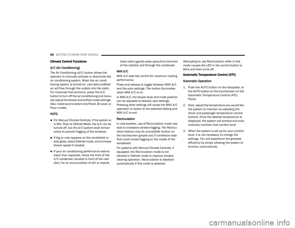
The Air Conditioning (A/C) button allows the
operator to manually activate or deactivate the
air conditioning system. When the air condi -
tioning system is turned on, cool dehumidified
air will flow through the outlets into the cabin.
For improved fuel economy, press the A/C
button to turn off the air conditioning and manu -
ally adjust the blower and airflow mode settings.
Also, make sure to select only Panel, Bi-Level, or
Floor modes.
NOTE:
For Manual Climate Controls, if the system is
in Mix, Floor or Defrost Mode, the A/C can be
turned off, but the A/C system shall remain
active to prevent fogging of the windows.
If fog or mist appears on the windshield or
side glass, select Defrost mode, and increase
blower speed if needed.
If your air conditioning performance seems
lower than expected, check the front of the
A/C condenser (located in front of the radi -
ator), for an accumulation of dirt or insects. Clean with a gentle water spray from the front
of the radiator and through the condenser.
MAX A/C
MAX A/C sets the control for maximum cooling
performance.
Press and release to toggle between MAX A/C
and the prior settings. The button illuminates
when MAX A/C is on.
In MAX A/C, the blower level and mode position
can be adjusted to desired user settings.
Pressing other settings will cause the MAX A/C
operation to switch to the selected setting and
MAX A/C to exit.
Recirculation
In cold weather, use of Recirculation mode may
lead to excessive window fogging. The Recircu -
lation feature may be unavailable (button on
the touchscreen greyed out) if conditions exist
that could create fogging on the inside of the
windshield.
On systems with Manual Climate Controls, if
equipped, the Recirculation mode is not
allowed in Defrost mode to improve window
clearing operation. Recirculation is disabled
automatically if this mode is selected. Attempting to use Recirculation while in this
mode causes the LED in the control button to
blink and then turns off.
Automatic Temperature Control (ATC)
Automatic Operation
1. Push the AUTO button on the faceplate, or the AUTO button on the touchscreen on the
Automatic Temperature Control (ATC)
Panel.
2. Next, adjust the temperature you would like the system to maintain by adjusting the
driver and passenger temperature control
buttons. Once the desired temperature is
displayed, the system will achieve and auto -
matically maintain that comfort level.
3. When the system is set up for your comfort level, it is not necessary to change the
settings. You will experience the greatest
efficiency by simply allowing the system to
function automatically.
20_DJD2_OM_EN_USC_t.book Page 68
Page 71 of 553

GETTING TO KNOW YOUR VEHICLE69
NOTE:
It is not necessary to move the temperature
settings for cold or hot vehicles. The system
automatically adjusts the temperature,
mode, and blower speed to provide comfort
as quickly as possible.
The temperature can be displayed in U.S. or
Metric units by selecting the U.S./Metric
customer-programmable feature. Refer to
the “Uconnect Settings” in “Multimedia” for
further information.
To provide you with maximum comfort in the
Automatic mode during cold start-ups, the
blower fan will remain on low until the engine
warms up. The blower will increase in speed
and transition into Auto mode.
Manual Operation Override
This system offers a full complement of manual
override features. The AUTO symbol in the front
ATC display will be turned off when the system
is being used in the manual mode.
Operating Tips
NOTE:
Refer to the chart at the end of this section for
suggested control settings for various weather
conditions.
Summer Operation
The engine cooling system must be protected
with a high-quality antifreeze coolant to provide
proper corrosion protection and to protect
against engine overheating. OAT coolant
(conforming to MS.90032) is recommended.
Winter Operation
To ensure the best possible heater and
defroster performance, make sure the engine
cooling system is functioning properly and the
proper amount, type, and concentration of
coolant is used. Use of the Air Recirculation
mode during Winter months is not recom -
mended, because it may cause window fogging.
Vacation/Storage
Before you store your vehicle, or keep it out of
service (i.e., vacation) for two weeks or more,
run the air conditioning system at idle for about
five minutes, in fresh air with the blower setting
on high. This will ensure adequate system lubri -cation to minimize the possibility of compressor
damage when the system is started again.
Window Fogging
Vehicle windows tend to fog on the inside in
mild, rainy, and/or humid weather. To clear the
windows, select Defrost or Mix mode and
increase the front blower speed. Do not use the
Recirculation mode without A/C for long
periods, as fogging may occur.
CAUTION!
Failure to follow these cautions can cause
damage to the heating elements:
Use care when washing the inside of the
rear window. Do not use abrasive window
cleaners on the interior surface of the
window. Use a soft cloth and a mild
washing solution, wiping parallel to the
heating elements. Labels can be peeled off
after soaking with warm water.
Do not use scrapers, sharp instruments, or
abrasive window cleaners on the interior
surface of the window.
Keep all objects a safe distance from the
window.
2
20_DJD2_OM_EN_USC_t.book Page 69
Page 95 of 553

GETTING TO KNOW YOUR VEHICLE93
There are stampings in the sheet metal on the
inner side bulkheads of the box in front of and
behind both wheel housings. Place wooden
boards across the box from side to side to
create separate load compartments in the
pickup box.
There are four tie-down cleats bolted to the
lower sides of the pickup box that can sustain
loads up to 1000 lbs (450 kg) total.
Cargo Camera — If Equipped
Your vehicle may be equipped with the Cargo
Camera that allows you to see an image of the
inside of the pickup box. The image will be
displayed in the Uconnect screen.
The Cargo Camera is located in the bottom
center area of the Center High-Mounted
Stoplamp (CHMSL).
A touchscreen button to indicate the current
active camera image being displayed is made
available whenever the Cargo Camera image is
displayed.
A touchscreen button to switch the display to
rear view camera image is made available
whenever the Cargo Camera image is displayed.
A touchscreen button "X" to disable display of
the camera image is made available when the
vehicle is not in REVERSE gear.
A display timer is initiated when the Cargo
Camera image is displayed. The image will
continue to be displayed until the display timer
exceeds 10 seconds and the vehicle speed is
above 8 mph (13 km/h) or the touchscreen
button "X" to disable display of the Cargo
Camera image is pressed. Cargo Camera With Dynamic Centerline (Avail
-
able With Surround View Camera Only) — If
Equipped
The Dynamic Centerline feature provides an
overlay on the Cargo Camera display screen
that aligns to the center of the pickup box to aid
in hooking up a fifth wheel camper or goose -
neck trailer. The centerline auto aligns to the
center of the pickup box, and can also be manu -
ally adjusted. The centerline will adjust in
response to steering angle inputs, and will not
obstruct the gooseneck receiver or an
approaching trailer gooseneck in the camera
feed.
Activation
The Dynamic Centerline feature can be acti -
vated through the Uconnect settings by
pressing the Cargo Camera soft button,
followed by the “Adjust Centerline” soft button
on the touchscreen.
If the Dynamic Centerline feature is turned on,
the overlay will display anytime the Cargo
Camera image is displayed.If you wish to carry more than 600 lbs
(272 kg) of material suspended above the
wheelhouse, supports must be installed to
transfer the weight of the load to the pickup
box floor or vehicle damage may result. The
use of proper supports will permit loading
up to the rated payload.
Unrestrained cargo may be thrown forward
in an accident causing serious or fatal
injury.
WARNING! (Continued)
2
20_DJD2_OM_EN_USC_t.book Page 93
Page 96 of 553

94GETTING TO KNOW YOUR VEHICLE
Adjusting Centerline
Follow the steps below to manually adjust the
centerline:
1. Press the “Adjust Centerline” soft button
located in the bottom right corner of the
Cargo Camera display.
2. Use the arrows on the bottom left corner of the Cargo Camera display to adjust the
centerline horizontally or vertically.
3. Once the desired position is achieved, press the “Accept” button to set the centerline to
the newly specified position.
Deactivation
The Dynamic Centerline feature will automati -
cally be deactivated whenever the Cargo
Camera display is deactivated. It can also be
manually deactivated through the Uconnect
settings.
For further information, refer to “Surround View
Camera System” in “Starting And Operating.” NOTE:
If the vehicle speed remains below 8 mph
(13 km/h), the Cargo Camera image will be
displayed continuously until the touchscreen
button "X" to disable display of the Cargo
Camera image is pressed.
The touchscreen button “X” to disable the
display of the camera image is made avail
-
able ONLY when the vehicle is not in reverse.
If snow, ice, mud, or any foreign substance
builds up on the camera lens, clean the lens,
rinse with water, and dry with a soft cloth. Do
not cover the lens.
Turning Cargo Camera On Or Off — With
Uconnect 4C/4C NAV
1. Press the “Controls” button located on the
bottom of the Uconnect display.
2. Press the “Cargo Camera” button to turn the Cargo Camera system on. NOTE:
Once initiated by the "Cargo Camera" button,
the Cargo Camera image will be displayed until
the vehicle speed remains below 8 mph
(13 km/h) and the 10 second timer runs out.
The image may be deactivated by pressing the
"X" soft button, placing the ignition in the OFF
position, placing the gear selector in PARK, or
pressing the image defeat “X” button. On deac
-
tivation, the previous selected screen will
appear.
RAMBOX — IF EQUIPPED
The RamBox system is an integrated pickup box
storage and cargo management system
consisting of up to three features:
Integrated box side storage bins
Cargo divider (if equipped)
Bed rail tie-down system (if equipped)
There will also be a 115 Volt (400 Watt) power
inverter located in the RamBox. Refer to
“Internal Equipment” in this chapter for further
information.
20_DJD2_OM_EN_USC_t.book Page 94
Page 111 of 553
GETTING TO KNOW YOUR INSTRUMENT PANEL109
Base / Midline Instrument Cluster
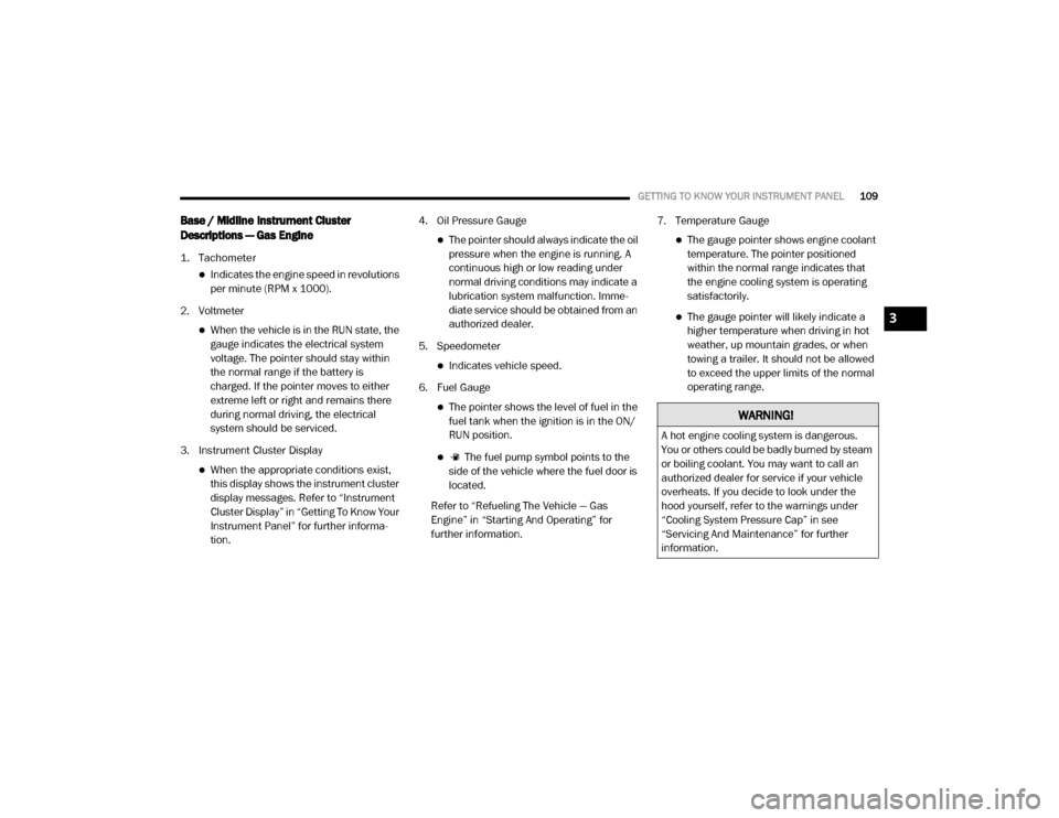
Descriptions — Gas Engine
1. Tachometer
Indicates the engine speed in revolutions
per minute (RPM x 1000).
2. Voltmeter
When the vehicle is in the RUN state, the gauge indicates the electrical system
voltage. The pointer should stay within
the normal range if the battery is
charged. If the pointer moves to either
extreme left or right and remains there
during normal driving, the electrical
system should be serviced.
3. Instrument Cluster Display
When the appropriate conditions exist, this display shows the instrument cluster
display messages. Refer to “Instrument
Cluster Display” in “Getting To Know Your
Instrument Panel” for further informa -
tion. 4. Oil Pressure Gauge
The pointer should always indicate the oil
pressure when the engine is running. A
continuous high or low reading under
normal driving conditions may indicate a
lubrication system malfunction. Imme -
diate service should be obtained from an
authorized dealer.
5. Speedometer
Indicates vehicle speed.
6. Fuel Gauge
The pointer shows the level of fuel in the fuel tank when the ignition is in the ON/
RUN position.
The fuel pump symbol points to the
side of the vehicle where the fuel door is
located.
Refer to “Refueling The Vehicle — Gas
Engine” in “Starting And Operating” for
further information. 7. Temperature Gauge
The gauge pointer shows engine coolant
temperature. The pointer positioned
within the normal range indicates that
the engine cooling system is operating
satisfactorily.
The gauge pointer will likely indicate a higher temperature when driving in hot
weather, up mountain grades, or when
towing a trailer. It should not be allowed
to exceed the upper limits of the normal
operating range.
WARNING!
A hot engine cooling system is dangerous.
You or others could be badly burned by steam
or boiling coolant. You may want to call an
authorized dealer for service if your vehicle
overheats. If you decide to look under the
hood yourself, refer to the warnings under
“Cooling System Pressure Cap” in see
“Servicing And Maintenance” for further
information.
3
20_DJD2_OM_EN_USC_t.book Page 109
Page 114 of 553
112GETTING TO KNOW YOUR INSTRUMENT PANEL
Premium Instrument Cluster Descriptions —
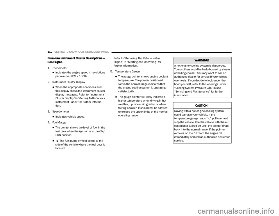
Gas Engine
1. Tachometer
Indicates the engine speed in revolutions
per minute (RPM x 1000).
2. Instrument Cluster Display
When the appropriate conditions exist, this display shows the instrument cluster
display messages. Refer to “Instrument
Cluster Display” in “Getting To Know Your
Instrument Panel” for further informa -
tion.
3. Speedometer
Indicates vehicle speed.
4. Fuel Gauge
The pointer shows the level of fuel in the fuel tank when the ignition is in the ON/
RUN position.
The fuel pump symbol points to the
side of the vehicle where the fuel door is
located. Refer to “Refueling The Vehicle — Gas
Engine” in “Starting And Operating” for
further information.
5. Temperature Gauge
The gauge pointer shows engine coolant temperature. The pointer positioned
within the normal range indicates that
the engine cooling system is operating
satisfactorily.
The gauge pointer will likely indicate a higher temperature when driving in hot
weather, up mountain grades, or when
towing a trailer. It should not be allowed
to exceed the upper limits of the normal
operating range.
WARNING!
A hot engine cooling system is dangerous.
You or others could be badly burned by steam
or boiling coolant. You may want to call an
authorized dealer for service if your vehicle
overheats. If you decide to look under the
hood yourself, refer to the warnings under
“Cooling System Pressure Cap” in see
“Servicing And Maintenance” for further
information.
CAUTION!
Driving with a hot engine cooling system
could damage your vehicle. If the
temperature gauge reads “H,” pull over and
stop the vehicle. Idle the vehicle with the air
conditioner turned off until the pointer drops
back into the normal range. If the pointer
remains on the “H,” turn the engine off
immediately and call an authorized dealer for
service.
20_DJD2_OM_EN_USC_t.book Page 112
Page 116 of 553
114GETTING TO KNOW YOUR INSTRUMENT PANEL
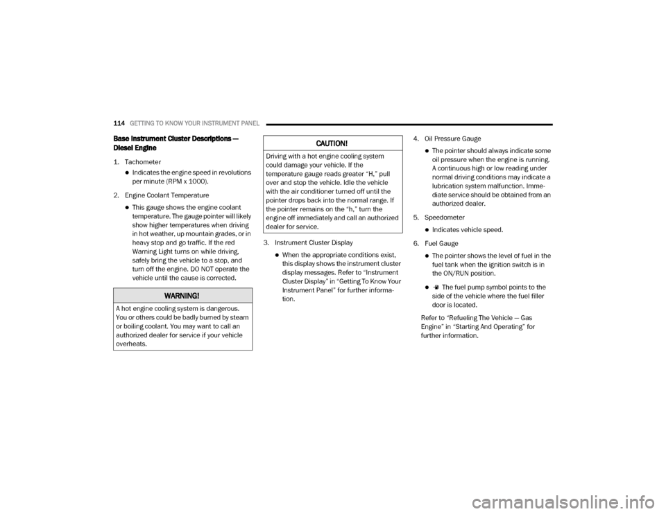
Base Instrument Cluster Descriptions —
Diesel Engine
1. Tachometer
Indicates the engine speed in revolutions
per minute (RPM x 1000).
2. Engine Coolant Temperature
This gauge shows the engine coolant temperature. The gauge pointer will likely
show higher temperatures when driving
in hot weather, up mountain grades, or in
heavy stop and go traffic. If the red
Warning Light turns on while driving,
safely bring the vehicle to a stop, and
turn off the engine. DO NOT operate the
vehicle until the cause is corrected. 3. Instrument Cluster Display
When the appropriate conditions exist,
this display shows the instrument cluster
display messages. Refer to “Instrument
Cluster Display” in “Getting To Know Your
Instrument Panel” for further informa -
tion. 4. Oil Pressure Gauge
The pointer should always indicate some
oil pressure when the engine is running.
A continuous high or low reading under
normal driving conditions may indicate a
lubrication system malfunction. Imme -
diate service should be obtained from an
authorized dealer.
5. Speedometer
Indicates vehicle speed.
6. Fuel Gauge
The pointer shows the level of fuel in the fuel tank when the ignition switch is in
the ON/RUN position.
The fuel pump symbol points to the
side of the vehicle where the fuel filler
door is located.
Refer to “Refueling The Vehicle — Gas
Engine” in “Starting And Operating” for
further information.
WARNING!
A hot engine cooling system is dangerous.
You or others could be badly burned by steam
or boiling coolant. You may want to call an
authorized dealer for service if your vehicle
overheats.
CAUTION!
Driving with a hot engine cooling system
could damage your vehicle. If the
temperature gauge reads greater “H,” pull
over and stop the vehicle. Idle the vehicle
with the air conditioner turned off until the
pointer drops back into the normal range. If
the pointer remains on the “h,” turn the
engine off immediately and call an authorized
dealer for service.
20_DJD2_OM_EN_USC_t.book Page 114
Page 117 of 553

GETTING TO KNOW YOUR INSTRUMENT PANEL115
7. Diesel Exhaust Fluid (DEF) Gauge
The DEF Gauge displays the actual level
of Diesel Exhaust Fluid in the DEF tank.
Diesel Exhaust Fluid (DEF) is required to
maintain normal vehicle operation and
emissions compliance. If something is
wrong with the gauge, a DEF Warning
Message or Malfunction Indicator Light
(MIL) will be displayed. More information
is available in the instrument cluster
display section under the heading of
Diesel Exhaust Fluid (DEF) Warning
Messages. NOTE:The gauge may take up to five seconds to
update after adding a gallon or more of
Diesel Exhaust Fluid (DEF) to the DEF tank. If
you have a fault related to the DEF system,
the gauge may not update to the new level.
See an authorized dealer for service.
The DEF gauge may also not immediately
update after a refill if the temperature of the
DEF fluid is below 39°F (4°C). The DEF tank
heater will warm up the DEF fluid and allow
the gauge to update after a period of run
time. Under very cold conditions, it is possible
that the gauge may not reflect the new fill
level for several drives.
3
20_DJD2_OM_EN_USC_t.book Page 115
Page 119 of 553
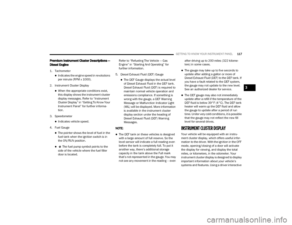
GETTING TO KNOW YOUR INSTRUMENT PANEL117
Premium Instrument Cluster Descriptions —
Diesel Engine
1. Tachometer
Indicates the engine speed in revolutions
per minute (RPM x 1000).
2. Instrument Cluster Display
When the appropriate conditions exist, this display shows the instrument cluster
display messages. Refer to “Instrument
Cluster Display” in “Getting To Know Your
Instrument Panel” for further informa -
tion.
3. Speedometer
Indicates vehicle speed.
4. Fuel Gauge
The pointer shows the level of fuel in the fuel tank when the ignition switch is in
the ON/RUN position.
The fuel pump symbol points to the
side of the vehicle where the fuel filler
door is located. Refer to “Refueling The Vehicle — Gas
Engine” in “Starting And Operating” for
further information.
5. Diesel Exhaust Fluid (DEF) Gauge
The DEF Gauge displays the actual level of Diesel Exhaust Fluid in the DEF tank.
Diesel Exhaust Fluid (DEF) is required to
maintain normal vehicle operation and
emissions compliance. If something is
wrong with the gauge, a DEF Warning
Message or Malfunction Indicator Light
(MIL) will be displayed. More information
is available in the instrument cluster
display section under the heading of
Diesel Exhaust Fluid (DEF) Warning
Messages.
NOTE:
The DEF tank on these vehicles is designed
with a large amount of full reserve. So the
level sensor will indicate a full reading even
before the tank is completely full. To put it
another way, there’s additional storage
capacity in the tank above the Full mark
that’s not represented in the gauge. You may
not see any movement in the reading – even after driving up to 200 miles (322 kilome
-
ters) in some cases.
The gauge may take up to five seconds to
update after adding a gallon or more of
Diesel Exhaust Fluid (DEF) to the DEF tank. If
you have a fault related to the DEF system,
the gauge may not update to the new level.
See an authorized dealer for service.
The DEF gauge may also not immediately
update after a refill if the temperature of the
DEF fluid is below 39°F (4°C). The DEF tank
heater will warm up the DEF fluid and allow
the gauge to update after a period of run
time. Under very cold conditions, it is possible
that the gauge may not reflect the new fill
level for several drives.
INSTRUMENT CLUSTER DISPLAY
Your vehicle will be equipped with an instru -
ment cluster display, which offers useful infor -
mation to the driver. With the ignition in the OFF
mode, opening/closing of a door will activate
the display for viewing, and display the total
miles, or kilometers, in the odometer. Your
instrument cluster display is designed to display
important information about your vehicle’s
systems and features. Using a driver interactive
3
20_DJD2_OM_EN_USC_t.book Page 117
Page 120 of 553
118GETTING TO KNOW YOUR INSTRUMENT PANEL
display located on the instrument panel, your
instrument cluster display can show you how
systems are working and give you warnings
when they are not. The steering wheel mounted
controls allow you to scroll through the main
menus and submenus. You can access the
specific information you want and make selec-
tions and adjustments.
Instrument Cluster Display Controls
The instrument cluster display features a driver
interactive display that is located in the instru -
ment cluster.
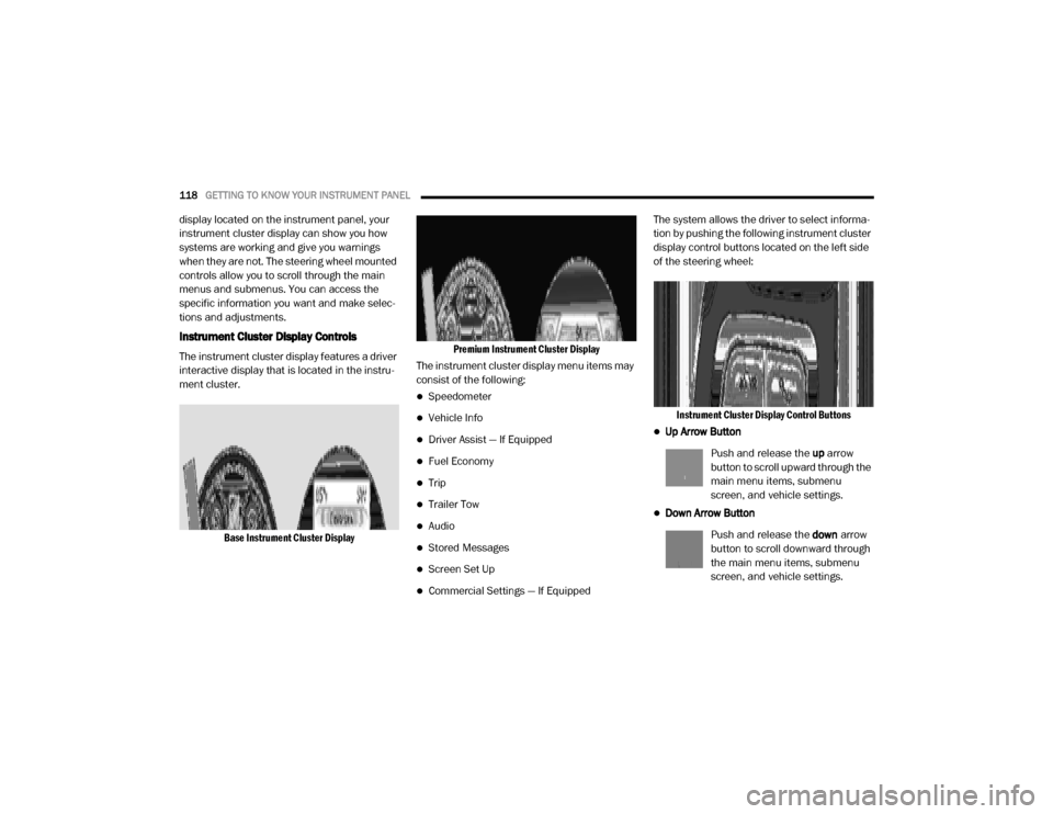
Base Instrument Cluster Display Premium Instrument Cluster Display
The instrument cluster display menu items may
consist of the following:
Speedometer
Vehicle Info
Driver Assist — If Equipped
Fuel Economy
Trip
Trailer Tow
Audio
Stored Messages
Screen Set Up
Commercial Settings — If Equipped The system allows the driver to select informa
-
tion by pushing the following instrument cluster
display control buttons located on the left side
of the steering wheel:
Instrument Cluster Display Control Buttons
Up Arrow Button
Push and release the up arrow
button to scroll upward through the
main menu items, submenu
screen, and vehicle settings.
Down Arrow Button
Push and release the down arrow
button to scroll downward through
the main menu items, submenu
screen, and vehicle settings.
20_DJD2_OM_EN_USC_t.book Page 118