ignition Ram 2500 2020 Owner's Guide
[x] Cancel search | Manufacturer: RAM, Model Year: 2020, Model line: 2500, Model: Ram 2500 2020Pages: 553, PDF Size: 21.99 MB
Page 76 of 553
74GETTING TO KNOW YOUR VEHICLE
Sunshade Operation
The sunshade can be opened manually.
However, the sunshade will open automatically
as the sunroof opens.
NOTE:
The sunshade cannot be closed if the sunroof is
open.
Pinch Protect Feature
This feature will detect an obstruction in the
closing of the sunroof during the Express Close
operation. If an obstruction in the path of the
sunroof is detected, the sunroof will automati-
cally retract. Remove the obstruction if this
occurs.
NOTE:
If three consecutive sunroof close attempts
result in Pinch Protect reversals, Pinch Protect
will disable and the sunroof must be closed in
Manual Mode.
Venting Sunroof — Express
Push and release the Vent button within one
half second and the sunroof will open to the
vent position. This is called “Express Vent”, and
it will occur regardless of sunroof position. During Express Vent operation, any other actua-
tion of the switch will stop the sunroof.
Sunroof Maintenance
Use only a non-abrasive cleaner and a soft cloth
to clean the glass panel.
Ignition Off Operation
The power sunroof switch will remain active for
up to approximately 10 minutes after the igni
-
tion switch is placed in the OFF position.
Opening either front door will cancel this
feature.
NOTE:
Ignition Off time is programmable through the
Uconnect System. Refer to “Uconnect Settings”
in “Multimedia” for further information.
HOOD
To Open The Hood
To open the hood, two latches must be
released.
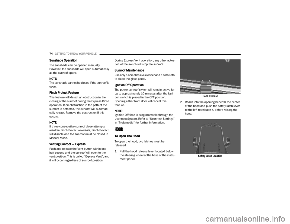
1. Pull the hood release lever located below the steering wheel at the base of the instru -
ment panel.
Hood Release
2. Reach into the opening beneath the center of the hood and push the safety latch lever
to the left to release it, before raising the
hood.
Safety Latch Location
20_DJD2_OM_EN_USC_t.book Page 74
Page 79 of 553
GETTING TO KNOW YOUR VEHICLE77
NOTE:
HomeLink® is disabled when the Vehicle Secu -
rity Alarm is active. NOTE:
Only use this transceiver with a garage door
opener that has a “stop and reverse” feature as
required by federal safety standards. This
includes most garage door opener models
manufactured after 1982. Do not use a garage
door opener without these safety features. Call
toll-free 1-800-355-3515 or, on the Internet at
HomeLink.com
for safety information or assis -
tance.
Before You Begin Programming HomeLink®
Be sure that your vehicle is parked outside of
the garage before you begin programming.
For more efficient programming and accurate
transmission of the Radio Frequency (RF) signal
it is recommended that a new battery be placed
in the hand-held transmitter of the device that is
being programmed to the HomeLink® system.
To erase the channels, place the ignition in the
ON/RUN position, and push and hold the two
outside HomeLink® buttons (I and III) for up to
20 seconds or until the orange indicator
flashes. NOTE:
Erasing all channels should only be
performed when programming HomeLink®
for the first time. Do not erase channels when
programming additional buttons.
If you have any problems, or require assis
-
tance, please call toll-free 1-800-355-3515
or, on the Internet at HomeLink.com for infor-
mation or assistance.
Programming A Rolling Code
For programming garage door openers that
were manufactured after 1995. These garage
door openers can be identified by the “LEARN”
or “TRAIN” button located where the hanging
antenna is attached to the garage door opener.
NOTE:
It is NOT the button that is normally used to
open and close the door. The name and color of
the button may vary by manufacturer.
WARNING!
Your motorized door or gate will open and
close while you are programming the
universal transceiver. Do not program the
transceiver if people, pets or other objects
are in the path of the door or gate. Only use
this transceiver with a garage door opener
that has a “stop and reverse” feature as
required by Federal safety standards. This
includes most garage door opener models
manufactured after 1982. Do not use a
garage door opener without these safety
features.
Vehicle exhaust contains carbon monoxide,
a dangerous gas. Do not run your vehicle in
the garage while programming the trans -
ceiver. Exhaust gas can cause serious
injury or death.
2
20_DJD2_OM_EN_USC_t.book Page 77
Page 80 of 553
78GETTING TO KNOW YOUR VEHICLE
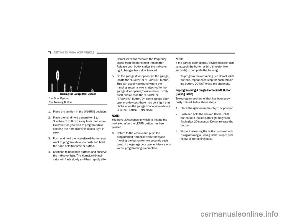
Training The Garage Door Opener
1. Place the ignition in the ON/RUN position.
2. Place the hand-held transmitter 1 to 3 inches (3 to 8 cm) away from the Home-
Link® button you wish to program while
keeping the HomeLink® indicator light in
view.
3. Push and hold the HomeLink® button you want to program while you push and hold
the hand-held transmitter button.
4. Continue to hold both buttons and observe the indicator light. The HomeLink® indi-
cator will flash slowly and then rapidly after HomeLink® has received the frequency
signal from the hand-held transmitter.
Release both buttons after the indicator
light changes from slow to rapid.
5. On the garage door opener (in the garage), locate the “LEARN” or “TRAINING” button.
This can usually be found where the
hanging antenna wire is attached to the
garage door opener/device motor. Firmly
push and release the “LEARN” or
“TRAINING” button. On some garage door
openers/devices, there may be a light that
blinks when the garage door opener/device
is in the LEARN/TRAIN mode.
NOTE:
You have 30 seconds in which to initiate the
next step after the LEARN button has been
pushed.
6. Return to the vehicle and push the programmed HomeLink® button twice
(holding the button for two seconds each
time). If the garage door opener/device acti -
vates, programming is complete. NOTE:
If the garage door opener/device does not acti
-
vate, push the button a third time (for two
seconds) to complete the training.
To program the remaining two HomeLink®
buttons, repeat each step for each remain -
ing button. DO NOT erase the channels.
Reprogramming A Single HomeLink® Button
(Rolling Code)
To reprogram a channel that has been previ -
ously trained, follow these steps:
1. Place the ignition in the ON/RUN position.
2. Push and hold the desired HomeLink® button until the indicator light begins to
flash after 20 seconds. Do not release the
button.
3. Without releasing the button proceed with “Programming A Rolling Code” step 2 and
follow all remaining steps.
1 — Door Opener
2 — Training Button
20_DJD2_OM_EN_USC_t.book Page 78
Page 81 of 553

GETTING TO KNOW YOUR VEHICLE79
Programming A Non-Rolling Code
For programming garage door openers manu -
factured before 1995.
1. Place the ignition in the ON/RUN position.
2. Place the hand-held transmitter 1 to 3 inches (3 to 8 cm) away from the Home-
Link® button you wish to program while
keeping the HomeLink® indicator light in
view.
3. Press and hold the HomeLink® button you want to program while you press and hold
the hand-held transmitter button.
4. Continue to hold both buttons and observe the indicator light. The HomeLink® indi-
cator will flash slowly and then rapidly after
HomeLink® has received the frequency
signal from the hand-held transmitter.
Release both buttons after the indicator
light changes from slow to rapid.
5. Press and hold the programmed Home -
Link® button and observe the indicator
light.
If the indicator light stays on constantly, programming is complete and the garage door/device should activate when the
HomeLink® button is pressed.
To program the two remaining Home
-
Link® buttons, repeat each step for each
remaining button. DO NOT erase the
channels.
Reprogramming A Single HomeLink® Button
(Non-Rolling Code)
To reprogram a channel that has been previ -
ously trained, follow these steps:
1. Place the ignition in the ON/RUN position.
2. Press and hold the desired HomeLink® button until the indicator light begins to
flash after 20 seconds. Do not release the
button.
3. Without releasing the button, proceed with “Programming A Non-Rolling Code” step 2
and follow all remaining steps.
Canadian/Gate Operator Programming
For programming transmitters in Canada/
United States that require the transmitter
signals to “time-out” after several seconds of
transmission. Canadian radio frequency laws require trans
-
mitter signals to time-out (or quit) after several
seconds of transmission – which may not be
long enough for HomeLink® to pick up the
signal during programming. Similar to this
Canadian law, some U.S. gate operators are
designed to time-out in the same manner.
It may be helpful to unplug the device during the
cycling process to prevent possible overheating
of the garage door or gate motor.
1. Place the ignition in the ON/RUN position.
2. Place the hand-held transmitter 1 to 3 inches (3 to 8 cm) away from the Home-
Link® button you wish to program while
keeping the HomeLink® indicator light in
view.
3. Continue to press and hold the HomeLink® button, while you press and release (cycle)
your hand-held transmitter every two
seconds until HomeLink® has successfully
accepted the frequency signal. The indi -
cator light will flash slowly and then rapidly
when fully trained.
2
20_DJD2_OM_EN_USC_t.book Page 79
Page 82 of 553
80GETTING TO KNOW YOUR VEHICLE
(Continued)
4. Watch for the HomeLink® indicator to change flash rates. When it changes, it is
programmed. It may take up to 30 seconds
or longer in rare cases. The garage door
may open and close while you are program -
ming.
5. Press and hold the programmed Home -
Link® button and observe the indicator
light.
NOTE:
If the indicator light stays on constantly,
programming is complete and the garage
door/device should activate when the Home -
Link® button is pressed.
To program the two remaining HomeLink®
buttons, repeat each step for each remaining
button. DO NOT erase the channels.
If you unplugged the garage door opener/
device for programming, plug it back in at this
time.
Reprogramming A Single HomeLink® Button
(Canadian/Gate Operator)
To reprogram a channel that has been previ -
ously trained, follow these steps:
1. Place the ignition in the ON/RUN position.
2. Press and hold the desired HomeLink®
button until the indicator light begins to
flash after 20 seconds. Do not release the
button.
3. Without releasing the button, proceed with “Canadian/Gate Operator Programming”
step 2 and follow all remaining steps.
Using HomeLink®
To operate, push and release the programmed
HomeLink® button. Activation will now occur for
the programmed device (i.e. garage door
opener, gate operator, security system, entry
door lock, home/office lighting, etc.) The
hand-held transmitter of the device may also be
used at any time.
Security
It is advised to erase all channels before you sell
or turn in your vehicle.
To do this, push and hold the two outside
buttons for 20 seconds until the orange indi -
cator flashes. Note that all channels will be
erased. Individual channels cannot be erased. The HomeLink® Universal Transceiver is disabled
when the Vehicle Security Alarm is active.
Troubleshooting Tips
If you are having trouble programming Home
-
Link®, here are some of the most common solu -
tions:
Replace the battery in the garage door
opener hand-held transmitter.
Push the LEARN button on the garage door
opener to complete the training for a Rolling
Code.
Did you unplug the device for programming
and remember to plug it back in?
If you have any problems, or require assistance,
please call toll-free1-800-355-3515 or, on the
Internet at HomeLink.com for information or
assistance.
WARNING!
Vehicle exhaust contains carbon monoxide,
a dangerous gas. Do not run your vehicle in
the garage while programming the trans -
ceiver. Exhaust gas can cause serious
injury or death.
20_DJD2_OM_EN_USC_t.book Page 80
Page 91 of 553
GETTING TO KNOW YOUR VEHICLE89
An auxiliary power outlet can be found in the
tray on top of the center stack. This power outlet
works when the ignition is in the ON/RUN, ACC,
or OFF position.
Power Outlet — Top Of Center Stack
Power Outlet Fuse Locations:
F104 Fuse 20 A Yellow UCI Port/ USB Rear
Center Console
F90 Fuse 20 A Yellow Instrument Panel
Power Outlet Battery Fed (If Equipped)
F91 Fuse 20 A Yellow Instrument Panel
Power Outlet Ignition Fed (If Equipped)
F93 Fuse 20 A Yellow Cigar Lighter/ Instru -
ment Panel Power Outlet (If Equipped)
When the vehicle is turned off, be sure to
unplug any equipment as to not drain the
battery of the vehicle. All accessories connected
to the outlet(s) should be removed or turned off
when the vehicle is not in use to protect the
battery against discharge.
Power outlets are designed for accessory
plugs only. Do not insert any other object in
the power outlets as this will damage the
outlet and blow the fuse. Improper use of
the power outlet can cause damage not
covered by your New Vehicle Limited
Warranty.
CAUTION! (Continued)
WARNING!
To avoid serious injury or death:
Only devices designed for use in this type of
outlet should be inserted into any 12 Volt
outlet.
Do not touch with wet hands.
Close the lid when not in use and while
driving the vehicle.
If this outlet is mishandled, it may cause an
electric shock and failure.
CAUTION!
Many accessories that can be plugged in
draw power from the vehicle's battery, even
when not in use (i.e., cellular phones, etc.).
Eventually, if plugged in long enough, the
vehicle's battery will discharge sufficiently
to degrade battery life and/or prevent the
engine from starting.
Accessories that draw higher power (i.e.,
coolers, vacuum cleaners, lights, etc.), will
discharge the battery even more quickly.
Only use these intermittently and with
greater caution.
After the use of high power draw accesso -
ries, or long periods of the vehicle not being
started (with accessories still plugged in),
the vehicle must be driven a sufficient
length of time to allow the generator to
recharge the vehicle's battery.
2
20_DJD2_OM_EN_USC_t.book Page 89
Page 96 of 553

94GETTING TO KNOW YOUR VEHICLE
Adjusting Centerline
Follow the steps below to manually adjust the
centerline:
1. Press the “Adjust Centerline” soft button
located in the bottom right corner of the
Cargo Camera display.
2. Use the arrows on the bottom left corner of the Cargo Camera display to adjust the
centerline horizontally or vertically.
3. Once the desired position is achieved, press the “Accept” button to set the centerline to
the newly specified position.
Deactivation
The Dynamic Centerline feature will automati -
cally be deactivated whenever the Cargo
Camera display is deactivated. It can also be
manually deactivated through the Uconnect
settings.
For further information, refer to “Surround View
Camera System” in “Starting And Operating.” NOTE:
If the vehicle speed remains below 8 mph
(13 km/h), the Cargo Camera image will be
displayed continuously until the touchscreen
button "X" to disable display of the Cargo
Camera image is pressed.
The touchscreen button “X” to disable the
display of the camera image is made avail
-
able ONLY when the vehicle is not in reverse.
If snow, ice, mud, or any foreign substance
builds up on the camera lens, clean the lens,
rinse with water, and dry with a soft cloth. Do
not cover the lens.
Turning Cargo Camera On Or Off — With
Uconnect 4C/4C NAV
1. Press the “Controls” button located on the
bottom of the Uconnect display.
2. Press the “Cargo Camera” button to turn the Cargo Camera system on. NOTE:
Once initiated by the "Cargo Camera" button,
the Cargo Camera image will be displayed until
the vehicle speed remains below 8 mph
(13 km/h) and the 10 second timer runs out.
The image may be deactivated by pressing the
"X" soft button, placing the ignition in the OFF
position, placing the gear selector in PARK, or
pressing the image defeat “X” button. On deac
-
tivation, the previous selected screen will
appear.
RAMBOX — IF EQUIPPED
The RamBox system is an integrated pickup box
storage and cargo management system
consisting of up to three features:
Integrated box side storage bins
Cargo divider (if equipped)
Bed rail tie-down system (if equipped)
There will also be a 115 Volt (400 Watt) power
inverter located in the RamBox. Refer to
“Internal Equipment” in this chapter for further
information.
20_DJD2_OM_EN_USC_t.book Page 94
Page 111 of 553
GETTING TO KNOW YOUR INSTRUMENT PANEL109
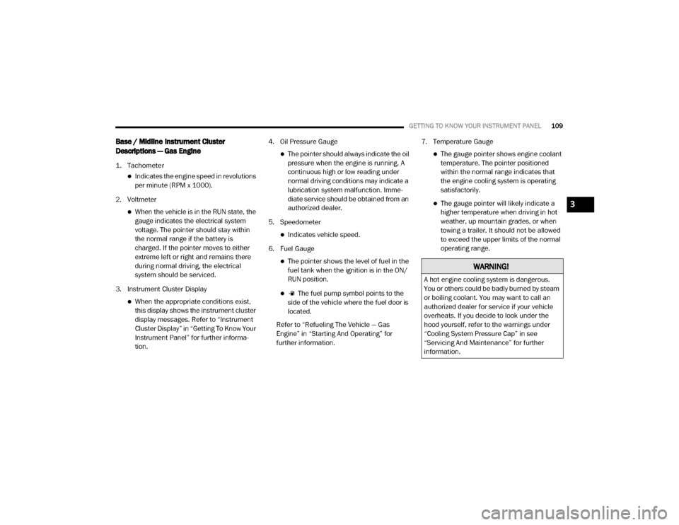
Base / Midline Instrument Cluster
Descriptions — Gas Engine
1. Tachometer
Indicates the engine speed in revolutions
per minute (RPM x 1000).
2. Voltmeter
When the vehicle is in the RUN state, the gauge indicates the electrical system
voltage. The pointer should stay within
the normal range if the battery is
charged. If the pointer moves to either
extreme left or right and remains there
during normal driving, the electrical
system should be serviced.
3. Instrument Cluster Display
When the appropriate conditions exist, this display shows the instrument cluster
display messages. Refer to “Instrument
Cluster Display” in “Getting To Know Your
Instrument Panel” for further informa -
tion. 4. Oil Pressure Gauge
The pointer should always indicate the oil
pressure when the engine is running. A
continuous high or low reading under
normal driving conditions may indicate a
lubrication system malfunction. Imme -
diate service should be obtained from an
authorized dealer.
5. Speedometer
Indicates vehicle speed.
6. Fuel Gauge
The pointer shows the level of fuel in the fuel tank when the ignition is in the ON/
RUN position.
The fuel pump symbol points to the
side of the vehicle where the fuel door is
located.
Refer to “Refueling The Vehicle — Gas
Engine” in “Starting And Operating” for
further information. 7. Temperature Gauge
The gauge pointer shows engine coolant
temperature. The pointer positioned
within the normal range indicates that
the engine cooling system is operating
satisfactorily.
The gauge pointer will likely indicate a higher temperature when driving in hot
weather, up mountain grades, or when
towing a trailer. It should not be allowed
to exceed the upper limits of the normal
operating range.
WARNING!
A hot engine cooling system is dangerous.
You or others could be badly burned by steam
or boiling coolant. You may want to call an
authorized dealer for service if your vehicle
overheats. If you decide to look under the
hood yourself, refer to the warnings under
“Cooling System Pressure Cap” in see
“Servicing And Maintenance” for further
information.
3
20_DJD2_OM_EN_USC_t.book Page 109
Page 114 of 553
112GETTING TO KNOW YOUR INSTRUMENT PANEL
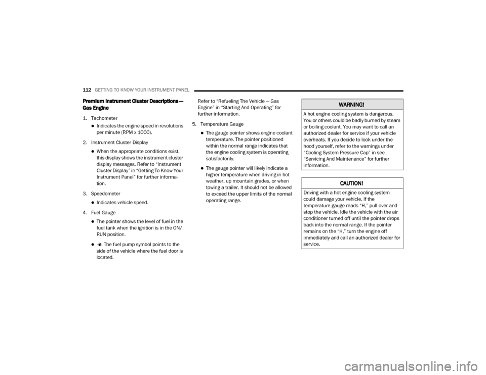
Premium Instrument Cluster Descriptions —
Gas Engine
1. Tachometer
Indicates the engine speed in revolutions
per minute (RPM x 1000).
2. Instrument Cluster Display
When the appropriate conditions exist, this display shows the instrument cluster
display messages. Refer to “Instrument
Cluster Display” in “Getting To Know Your
Instrument Panel” for further informa -
tion.
3. Speedometer
Indicates vehicle speed.
4. Fuel Gauge
The pointer shows the level of fuel in the fuel tank when the ignition is in the ON/
RUN position.
The fuel pump symbol points to the
side of the vehicle where the fuel door is
located. Refer to “Refueling The Vehicle — Gas
Engine” in “Starting And Operating” for
further information.
5. Temperature Gauge
The gauge pointer shows engine coolant temperature. The pointer positioned
within the normal range indicates that
the engine cooling system is operating
satisfactorily.
The gauge pointer will likely indicate a higher temperature when driving in hot
weather, up mountain grades, or when
towing a trailer. It should not be allowed
to exceed the upper limits of the normal
operating range.
WARNING!
A hot engine cooling system is dangerous.
You or others could be badly burned by steam
or boiling coolant. You may want to call an
authorized dealer for service if your vehicle
overheats. If you decide to look under the
hood yourself, refer to the warnings under
“Cooling System Pressure Cap” in see
“Servicing And Maintenance” for further
information.
CAUTION!
Driving with a hot engine cooling system
could damage your vehicle. If the
temperature gauge reads “H,” pull over and
stop the vehicle. Idle the vehicle with the air
conditioner turned off until the pointer drops
back into the normal range. If the pointer
remains on the “H,” turn the engine off
immediately and call an authorized dealer for
service.
20_DJD2_OM_EN_USC_t.book Page 112
Page 116 of 553
114GETTING TO KNOW YOUR INSTRUMENT PANEL
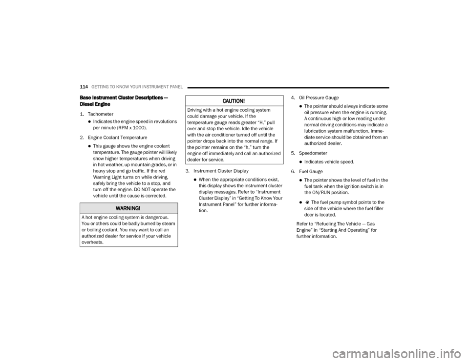
Base Instrument Cluster Descriptions —
Diesel Engine
1. Tachometer
Indicates the engine speed in revolutions
per minute (RPM x 1000).
2. Engine Coolant Temperature
This gauge shows the engine coolant temperature. The gauge pointer will likely
show higher temperatures when driving
in hot weather, up mountain grades, or in
heavy stop and go traffic. If the red
Warning Light turns on while driving,
safely bring the vehicle to a stop, and
turn off the engine. DO NOT operate the
vehicle until the cause is corrected. 3. Instrument Cluster Display
When the appropriate conditions exist,
this display shows the instrument cluster
display messages. Refer to “Instrument
Cluster Display” in “Getting To Know Your
Instrument Panel” for further informa -
tion. 4. Oil Pressure Gauge
The pointer should always indicate some
oil pressure when the engine is running.
A continuous high or low reading under
normal driving conditions may indicate a
lubrication system malfunction. Imme -
diate service should be obtained from an
authorized dealer.
5. Speedometer
Indicates vehicle speed.
6. Fuel Gauge
The pointer shows the level of fuel in the fuel tank when the ignition switch is in
the ON/RUN position.
The fuel pump symbol points to the
side of the vehicle where the fuel filler
door is located.
Refer to “Refueling The Vehicle — Gas
Engine” in “Starting And Operating” for
further information.
WARNING!
A hot engine cooling system is dangerous.
You or others could be badly burned by steam
or boiling coolant. You may want to call an
authorized dealer for service if your vehicle
overheats.
CAUTION!
Driving with a hot engine cooling system
could damage your vehicle. If the
temperature gauge reads greater “H,” pull
over and stop the vehicle. Idle the vehicle
with the air conditioner turned off until the
pointer drops back into the normal range. If
the pointer remains on the “h,” turn the
engine off immediately and call an authorized
dealer for service.
20_DJD2_OM_EN_USC_t.book Page 114