lights Ram 2500 2020 Service Manual
[x] Cancel search | Manufacturer: RAM, Model Year: 2020, Model line: 2500, Model: Ram 2500 2020Pages: 553, PDF Size: 21.99 MB
Page 336 of 553
334STARTING AND OPERATING
NOTE:
With electronic shift transfer case:
Steps 2 through 3 are requirements that
must be met before pushing the N (Neutral)
button, and must continue to be met until the
shift has been completed. If any of these
requirements are not met before pushing the
N (Neutral) button or are no longer met
during the shift, the N (Neutral) indicator light
will flash continuously until all requirements
are met or until the N (Neutral) button is
released.
The ignition must be in the ON/RUN mode for
a shift to take place and for the position indi -
cator lights to be operable. If the ignition is
not in the ON/RUN mode, the shift will not
take place and no position indicator lights will
be on or flashing.
A flashing N (Neutral) position indicator light
indicates that shift requirements have not
been met.
If the vehicle is equipped with air suspension,
the engine should be started and left running
for a minimum of 60 seconds (with all the
doors closed) at least once every 24 hours. This process allows the air suspension to
adjust the vehicle’s ride height to compen
-
sate for temperature effects.
Shifting Out Of (N) NEUTRAL
Use the following procedure to prepare your
vehicle for normal usage:
1. Bring the vehicle to a complete stop,
leaving it connected to the tow vehicle.
2. Firmly apply the parking brake.
3. Press and hold the brake pedal.
4. Start the engine. Shift the transmission into NEUTRAL.
With manual shift transfer case, shift the transfer case lever to the desired posi -
tion.
With electronic shift transfer case with rotary selector switch, push and hold the
transfer case N (Neutral) button until the
N (Neutral) indicator light turns off. After
the N (Neutral) indicator light turns off,
release the N (Neutral) button. After the
N (Neutral) button has been released, the
transfer case will shift to the position indi -
cated by the selector switch.
With electronic shift transfer case with push-button selector switch, push and
hold the switch for the desired transfer
case position, until the N (Neutral) indi -
cator light turns off and the desired posi -
tion indicator light turns on.
NOTE:
When shifting out of transfer case N (Neutral),
turning the engine OFF is not required, but may
be helpful to avoid gear clash. With the 8-speed
automatic transmission, the engine must
remain running, since turning the engine OFF
will shift the transmission to PARK (and the
transmission must be in NEUTRAL for the
transfer case to shift out of NEUTRAL).
5. Turn the engine off. Shift automatic trans -
mission into PARK. On 8-speed transmis -
sions the shifter will automatically select
PARK when the engine is turned off.
6. Release the brake pedal.
7. Disconnect vehicle from the tow vehicle.
8. Start the engine.
9. Press and hold the brake pedal.
20_DJD2_OM_EN_USC_t.book Page 334
Page 337 of 553

STARTING AND OPERATING335
(Continued)
10. Release the parking brake.
11. Shift the transmission into gear, release the brake pedal, and check that the vehicle
operates normally.
NOTE:
With electronic shift transfer case:
Steps 3 and 4 are requirements that must be
met before pushing the button to shift out of
N (Neutral), and must continue to be met
until the shift has been completed. If any of
these requirements are not met before
pushing the button or are no longer met
during the shift, the N (Neutral) indicator light
will flash continuously until all requirements
are met or until the button is released.
The ignition must be in the ON/RUN mode for
a shift to take place and for the position indi -
cator lights to be operable. If the ignition is
not in the ON/RUN mode, the shift will not
take place and no position indicator lights will
be on or flashing.
A flashing N (Neutral) position indicator light
indicates that shift requirements have not
been met.
DRIVING TIPS
Driving On Slippery Surfaces
Acceleration
Rapid acceleration on snow covered, wet, or
other slippery surfaces may cause the driving
wheels to pull erratically to the right or left. This
phenomenon occurs when there is a difference
in the surface traction under the rear (driving)
wheels.
Driving Through Water
Driving through water more than a few inches/
centimeters deep will require extra caution to
ensure safety and prevent damage to your
vehicle.
Flowing/Rising Water
Shallow Standing Water
Although your vehicle is capable of driving
through shallow standing water, consider the
following Cautions and Warnings before doing
so.
WARNING!
Rapid acceleration on slippery surfaces is
dangerous. Unequal traction can cause
sudden pulling of the rear wheels. You could
lose control of the vehicle and possibly have a
collision. Accelerate slowly and carefully
whenever there is likely to be poor traction
(ice, snow, wet, mud, loose sand, etc.).
WARNING!
Do not drive on or across a road or path
where water is flowing and/or rising (as in
storm run-off). Flowing water can wear away
the road or path's surface and cause your
vehicle to sink into deeper water.
Furthermore, flowing and/or rising water can
carry your vehicle away swiftly. Failure to
follow this warning may result in injuries that
are serious or fatal to you, your passengers,
and others around you.
WARNING!
Driving through standing water limits your
vehicle’s traction capabilities. Do not
exceed 5 mph (8 km/h) when driving
through standing water.
5
20_DJD2_OM_EN_USC_t.book Page 335
Page 358 of 553
356IN CASE OF EMERGENCY
F2225 Amp White (Cummins
Diesel) –
PCM – If Equipped
F23 30 Amp Pink –CBC Feed # 1
F24 30 Amp Pink –Driver Door Module
F25 30 Amp Pink –Front Wiper
F26 30 Amp Pink –Antilock Brakes / Stability Control Module / Valves – If
Equipped (DS 1500 Only)
F28 20 Amp Blue –Trailer Tow Backup Lights – If Equipped
F29 20 Amp Blue –Trailer Tow Parking Lights – If Equipped
F30 30 Amp Pink –Trailer Tow Receptacle / Trailer Tow (Separate E-Brake)/
Trailer Tow (BUX)
F31 30 Amp Pink –Diesel Heater Control – If Equipped (DS 1500 LD Diesel)
F31 20 Amp Blue –Aux App SSV Only - If Equipped
F32 ––Aux Feed, Special Services Vehicle-If Equipped (DS 1500
Only)
F33 20 Amp Blue –Trans Control Module – If Equipped (HD Only)
Aux Feed, SSV Only (DS 1500 Only)
F34 30 Amp Pink –Vehicle System Interface Module #2 – If Equipped (HD
Only)
SSV (DS 1500 Only)
F35 30 Amp Pink –Sunroof – If Equipped
F36 30 Amp Pink –Electric Back Light – If Equipped
Cavity Cartridge Fuse Micro Fuse Description
20_DJD2_OM_EN_USC_t.book Page 356
Page 359 of 553

IN CASE OF EMERGENCY357
F3730 Amp Pink –Fuel Heater #2, Aux Relay 2 – If Equipped (HD Only)
SSV (DS 1500 Only)
F38 30 Amp Pink –Integrated Trailer Brake Module – If Equipped (HD Only)
Power Inverter 115 Volts AC – If Equipped (DS 1500 Only)
F39 20 Amp Blue –Power Outlet – SSV Only
F40 –10 Amp Red Ventilated Seats – If Equipped (HD Only)
F41 –10 Amp Red Active Grille Shutter / Active Air Dam – If Equipped
F42 –20 Amp Yellow Horn
F43 –15 Amp Blue Heated Steering Wheel – If Equipped (HD Only)
F44 –10 Amp Red Diagnostic Port
F46 –10 Amp RedUpfitters Relay Coil – If Equipped (HD Only)
Spare (DS 1500 Only)
F49 –10 Amp RedInstrument Panel Cluster / HVAC (DS 1500 Only)
Instrument Cluster / MOD CSG (HD Only)
F50 –20 Amp Yellow Air Suspension Control Module – If Equipped
F51 –10 Amp RedIgnition Node Module / Keyless Ignition Node Module,
Radio Frequency Hub Module / Electric Steering Column
Lock - If Equipped
F52 –5 Amp Tan Battery Sensor
F53 –20 Amp Yellow Trailer Tow – Left Turn/Stop Lights - If Equipped
F54 –20 Amp Yellow Non Memory Adjustable Pedals - If Equipped
F56 –15 Amp Blue Additional Diesel Content - If Equipped (DS 1500 Only)
CavityCartridge Fuse Micro Fuse Description
6
20_DJD2_OM_EN_USC_t.book Page 357
Page 362 of 553
360IN CASE OF EMERGENCY
F78 –10 Amp RedEngine Control Module / Powertrain Control Module /
Electric Power Steering (DS 1500 Only)
F78 –15 Amp BlueEngine Control Module / Powertrain Control Module / AEB
RACM MOD / Feed To AUX PDC Relay Coils/ HRLS (HD
Only)
F79 –15 Amp Blue ID / Clearance Lights
F80 –10 Amp RedUniversal Garage Door Opener / Compass / Anti-Intrusion
Module (DS 1500 Only)
ASSY Overhead Console / SW Assist / SW 911 – If
Equipped (HD Only)
F81 –20 Amp Yellow Trailer Tow Right Turn / Stop Lights - If Equipped
F82 –10 Amp Red Steering Column Control Module / Cruise Control
F83 ––No Connection
F84 –15 Amp Blue ASBM / HVAC / ICS / Rear Heated Seat Switches
F85 –10 Amp Red Airbag Module
F86 –10 Amp Red Airbag Module
F87 –10 Amp RedAir Suspension / ITBM / Steering Column Control Module
/ MOD Gateway CAN-C Trailer TPM (HD Only)
Air Suspension / Trailer Tow / DC/DC Converter (Voltage
Stabilizer) / Steering Column Control Module / Occupant
Classification Sensor (DS 1500 Only)
F88 –15 Amp Blue Instrument Panel Cluster
CavityCartridge Fuse Micro Fuse Description
20_DJD2_OM_EN_USC_t.book Page 360
Page 382 of 553
380
SERVICING AND MAINTENANCE
SCHEDULED SERVICING — GAS ENGINE
Your vehicle is equipped with an automatic oil
change indicator system. The oil change indi-
cator system will remind you that it is time to
take your vehicle in for scheduled maintenance.
Based on engine operation conditions, the oil
change indicator message will illuminate. This
means that service is required for your vehicle.
Operating conditions such as frequent
short-trips, trailer tow, extremely hot or cold
ambient temperatures, and E85 fuel usage will
influence when the “Oil Change Required”
message is displayed. Severe Operating Condi-
tions can cause the change oil message to illu -
minate as early as 3,500 miles (5,600 km)
since last reset. Have your vehicle serviced as
soon as possible, within the next 500 miles
(805 km).
Your authorized dealer will reset the oil change
indicator message after completing the sched -
uled oil change.
If a scheduled oil change is performed by
someone other than your authorized dealer, the
message can be reset by referring to the steps described under “Instrument Cluster Display” in
“Getting To Know Your Instrument Panel”.
NOTE:
Under no circumstances should oil change
intervals exceed 8,000 miles (13,000 km),
12 months or 350 hours of engine run time,
whichever comes first. The 350 hours of engine
run or idle time is generally only a concern for
fleet customers.
Severe Duty All Models
NOTE:
Change Engine Oil at 4,000 miles (6,500 km) or
350 hours of engine run time if the vehicle is
operated in a dusty and off road environment or
is operated predominantly at idle, or only very
low engine RPM. This type of vehicle use is
considered Severe Duty.
Once A Month Or Before A Long Trip:
Check engine oil level
Check windshield washer fluid level
Check tire pressure and look for unusual
wear or damage. Rotate tires at the first sign
of irregular wear, even if it occurs before the
oil indicator system turns on.
Check the fluid levels of the coolant reservoir,
brake master cylinder, power steering and
automatic transmission (six-speed only) and
fill as needed
Check function of all interior and exterior
lights
Maintenance Plan — Gasoline Engine
Required Maintenance
Refer to the Maintenance Plan on the following
pages for required maintenance. More frequent
maintenance may be needed in severe condi
-
tions, such as dusty areas and very short trip
driving. In some extreme conditions, additional
maintenance not specified in the maintenance
schedule may be required.
20_DJD2_OM_EN_USC_t.book Page 380
Page 441 of 553
SERVICING AND MAINTENANCE439
Standard No. 109. Grades B and A repre -
sent higher levels of performance on the
laboratory test wheel, than the minimum
required by law.
STORING THE VEHICLE
If you are storing your vehicle for more than
21 days, we recommend that you take the
following steps to minimize the drain on your
vehicle's battery:
Disconnect the negative cable from battery.
Any time you store your vehicle or keep it out
of service (i.e., vacation) for two weeks or
more, run the air conditioning system at idle
for about five minutes in the fresh air and high blower setting. This will ensure
adequate system lubrication to minimize the
possibility of compressor damage when the
system is started again.
BODYWORK
Protection From Atmospheric Agents
Vehicle body care requirements vary according
to geographic locations and usage. Chemicals
that make roads passable in snow and ice and
those that are sprayed on trees and road
surfaces during other seasons are highly corro
-
sive to the metal in your vehicle. Outside
parking, which exposes your vehicle to airborne
contaminants, road surfaces on which the
vehicle is operated, extreme hot or cold weather
and other extreme conditions will have an
adverse effect on paint, metal trim, and under -
body protection.
The following maintenance recommendations
will enable you to obtain maximum benefit from
the corrosion resistance built into your vehicle.
What Causes Corrosion?
Corrosion is the result of deterioration or
removal of paint and protective coatings from
your vehicle. The most common causes are:
Road salt, dirt and moisture accumulation.
Stone and gravel impact.
Insects, tree sap and tar.
Salt in the air near seacoast localities.
Atmospheric fallout/industrial pollutants.
Body And Underbody Maintenance
Cleaning Headlights
Your vehicle is equipped with plastic headlights
and fog lights that are lighter and less suscep
-
tible to stone breakage than glass headlights.
Plastic is not as scratch resistant as glass and
therefore different lens cleaning procedures
must be followed.
To minimize the possibility of scratching the
lenses and reducing light output, avoid wiping
with a dry cloth. To remove road dirt, wash with
a mild soap solution followed by rinsing.
Do not use abrasive cleaning components,
solvents, steel wool or other aggressive mate -
rial to clean the lenses.
WARNING!
The temperature grade for this tire is
established for a tire that is properly inflated
and not overloaded. Excessive speed,
under-inflation, or excessive loading, either
separately or in combination, can cause heat
buildup and possible tire failure.
7
20_DJD2_OM_EN_USC_t.book Page 439
Page 461 of 553
MULTIMEDIA459
NOTE:
FCA US LLC or your dealer may contact you
directly regarding software updates.
To help further improve vehicle security and
minimize the potential risk of a security
breach, vehicle owners should:
Routinely check www.driveuconnect.com
(US Residents) or www.driveuconnect.ca
(Canadian Residents) to learn about
available Uconnect software updates.
Only connect and use trusted media devices (e.g. personal mobile phones,
USBs, CDs).
Privacy of any wireless and wired communica -
tions cannot be assured. Third parties may
unlawfully intercept information and private
communications without your consent. For
further information, refer to “Data Collection &
Privacy” in your Uconnect Owner’s Manual
Supplement or “Onboard Diagnostic System
(OBD II) Cybersecurity” in “Getting To Know Your
Instrument Panel”.
UCONNECT SETTINGS
The Uconnect system uses a combination of
buttons on the touchscreen and buttons on the
faceplate located on the center of the instru -
ment panel. These buttons allow you to access
and change the customer programmable
features. Many features can vary by vehicle.
Buttons on the faceplate are located below
and/or beside the Uconnect system in the
center of the instrument panel. In addition,
there is a Scroll/Enter control knob located on
the right side. Turn the control knob to scroll
through menus and change settings. Push the
center of the control knob one or more times to
select or change a setting.
Your Uconnect system may also have Screen
Off and Mute buttons on the faceplate.
Push the Screen Off button on the faceplate to
turn off the Uconnect screen. Push the button
again or tap the screen to turn the screen on.
Push the Back Arrow button to exit out of a
Menu or certain option on the Uconnect system.
Uconnect 3 Settings
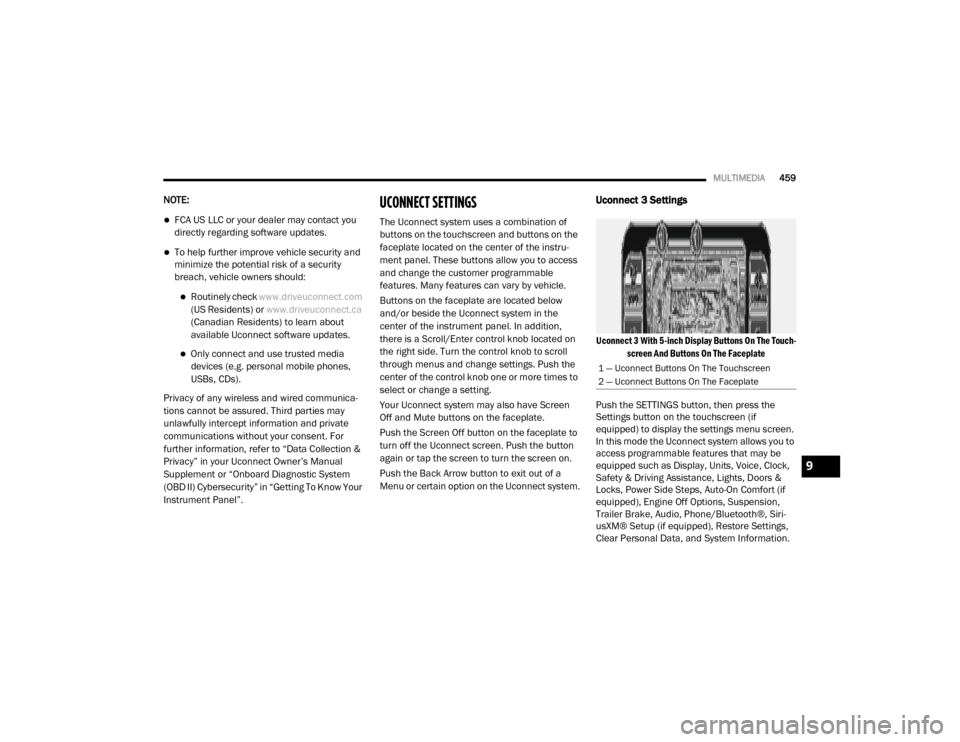
Uconnect 3 With 5-inch Display Buttons On The Touch -
screen And Buttons On The Faceplate
Push the SETTINGS button, then press the
Settings button on the touchscreen (if
equipped) to display the settings menu screen.
In this mode the Uconnect system allows you to
access programmable features that may be
equipped such as Display, Units, Voice, Clock,
Safety & Driving Assistance, Lights, Doors &
Locks, Power Side Steps, Auto-On Comfort (if
equipped), Engine Off Options, Suspension,
Trailer Brake, Audio, Phone/Bluetooth®, Siri -
usXM® Setup (if equipped), Restore Settings,
Clear Personal Data, and System Information.
1 — Uconnect Buttons On The Touchscreen
2 — Uconnect Buttons On The Faceplate
9
20_DJD2_OM_EN_USC_t.book Page 459
Page 467 of 553

MULTIMEDIA465
Lights
After pressing the Lights button on the touchscreen, the following settings will be available:
Setting Name Selectable Options
Headlight Off Delay0 sec
30 sec
60 sec 90 sec
Headlight Illumination On Approach 0 sec
30 sec
60 sec 90 sec
NOTE:
When the “Headlight Illumination On Approach” feature is selected, it allows the adjustment of the amount of time the headlights remain on when
the doors are unlocked with the key fob. Headlights With Wipers — If Equipped OnOff
Auto Dim High Beams — If Equipped OnOff
Flash Lights With Lock OnOff
NOTE:
When the “Flash Lights With Lock” feature is selected, the exterior lights flash when the doors are locked or unlocked with the key fob. This feature
may be selected with or without the Sound Horn On Lock feature selected. Steering Directed Lights - If Equipped OnOff
NOTE:
When the “Steering Directed Lights” feature is selected, the headlights turn with the direction of the steering wheel. Rear Cargo Guidance Lights — If Equipped OnOff
NOTE:
When the “Rear Cargo Guidance Lights” feature is selected, the lights in the cargo and bed of the truck will come on either when the headlight switch
is pressed, or the button on the back bed of the truck is pressed.
9
20_DJD2_OM_EN_USC_t.book Page 465
Page 469 of 553

MULTIMEDIA467
Power Side Steps — If Equipped
After pressing the Power Side Steps button on the touchscreen, the following settings will be available:
Auto-On Comfort Systems — If Equipped
After pressing the Auto-On Comfort Systems button on the touchscreen, the following settings will be available:Passive Entry — If Equipped
On Off
NOTE:
The “Passive Entry” feature allows you to lock and unlock the vehicle’s door(s) without having to push the key fob lock or unlock buttons. It automat -
ically unlocks the doors when the outside door handle is grabbed.
Flash Lights With Lock On Off
NOTE:
When the “Flash Lights With Lock” feature is selected, the exterior lights flash when the doors are locked or unlocked with the key fob. This feature
may be selected with or without the “Sound Horn With Lock” feature selected.
Setting Name Selectable Options
Setting NameSelectable Options
Power Side StepsAutomaticStow
Setting Name Selectable Options
Auto-On Driver Heated/Ventilated
Seat & Steering Wheel With Vehicle Start — If Equipped Off
Remote Start Only All Starts9
20_DJD2_OM_EN_USC_t.book Page 467