lights Ram 2500 2020 Owner's Guide
[x] Cancel search | Manufacturer: RAM, Model Year: 2020, Model line: 2500, Model: Ram 2500 2020Pages: 553, PDF Size: 21.99 MB
Page 97 of 553

GETTING TO KNOW YOUR VEHICLE95
RamBox Integrated Box Side Storage Bins
Cargo storage bins are located on both sides of
the pickup box. The cargo storage bins provide
watertight, lockable, illuminated storage for up
to 300 lbs (136 kg) of evenly distributed cargo.
RamBox Cargo Storage Bins
To open a storage bin with the RamBox
unlocked, push and release the button located
on the lid. The RamBox lid will open upward to
allow hand access. Lift the lid to fully open.
NOTE:
RamBox will not open when the button is
pushed if the RamBox is locked.
RamBox Pushbutton And Lock
The interior of the RamBox will automatically
illuminate when the lid is opened. In addition to
the automatic illumination, there is a manual
on/off switch located at the rear of each storage
bin. Pushing the switch once will turn off the bin
lights, pushing the switch again will turn the
lights back on.
RamBox Light Switch
Cargo bins feature two removable drain plugs
(to allow water to drain from bins). To remove
plug, pull up on the edge. To install, push the
plug downward into drain hole.
NOTE:
Provisions are provided in the bins for cargo
dividers and shelf supports. These accessories
(in addition to other RamBox accessories) are
available from Mopar.
CAUTION!
Failure to follow the following items could
cause damage to the vehicle:
Assure that all cargo inside the storage bins
is properly secured.
Do not exceed cargo weight rating of
300 lbs (136 kg) for 2500 and 3500
series vehicles per bin.
CAUTION!
Leaving the lid open for extended periods of
time could cause the vehicle battery to
discharge. If the lid is required to stay open
for extended periods of time, it is
recommended that the bin lights be turned
off manually using the on/off switch.
2
20_DJD2_OM_EN_USC_t.book Page 95
Page 131 of 553
GETTING TO KNOW YOUR INSTRUMENT PANEL129
NOTE:
The charging system is independent from
load reduction. The charging system
performs a diagnostic on the charging
system continuously.
If the Battery Charge Warning Light is on it
may indicate a problem with the charging
system. Refer to “Warning Lights And
Messages” in “Getting To Know Your Instru-
ment Panel” for further information.
The electrical loads that may be switched off (if
equipped), and vehicle functions which can be
affected by load reduction:
Heated Seats/Vented Seats/Heated Wheel
Rear Defroster And Heated Mirrors
HVAC System
115 Volts AC Power Inverter System
Audio and Telematics System Loss of the battery charge may indicate one or
more of the following conditions:
The charging system cannot deliver enough
electrical power to the vehicle system
because the electrical loads are larger than
the capability of charging system. The
charging system is still functioning properly.
Turning on all possible vehicle electrical
loads (e.g. HVAC to max settings, exterior and
interior lights, overloaded power outlets
+12 Volts, 115 Volts AC, USB ports) during
certain driving conditions (city driving,
towing, frequent stopping).
Installing options like additional lights,
upfitter electrical accessories, audio
systems, alarms and similar devices.
Unusual driving cycles (short trips separated
by long parking periods).
The vehicle was parked for an extended
period of time (weeks, months).
The battery was recently replaced and was
not charged completely.
The battery was discharged by an electrical
load left on when the vehicle was parked.
The battery was used for an extended period
with the engine not running to supply radio,
lights, chargers, +12 Volts portable appli
-
ances like vacuum cleaners, game consoles
and similar devices.
What to do when an electrical load reduction
action message is present (“Battery Saver On”
or “Battery Saver Mode”)
During a trip:
Reduce power to unnecessary loads if
possible:
Turn off redundant lights (interior or exte -
rior).
Check what may be plugged in to power outlets +12 Volts, 115 Volts AC, USB
ports.
Check HVAC settings (blower, tempera -
ture).
Check the audio settings (volume).
3
20_DJD2_OM_EN_USC_t.book Page 129
Page 132 of 553
130GETTING TO KNOW YOUR INSTRUMENT PANEL
After a trip:
Check if any aftermarket equipment was
installed (additional lights, upfitter electrical
accessories, audio systems, alarms) and
review specifications if any (load and Ignition
Off Draw currents).
Evaluate the latest driving cycles (distance,
driving time and parking time).
The vehicle should have service performed if
the message is still present during consecu-
tive trips and the evaluation of the vehicle
and driving pattern did not help to identify the
cause.
WARNING LIGHTS AND MESSAGES
The warning/indicator lights will illuminate in
the instrument panel together with a dedicated
message and/or acoustic signal when appli -
cable. These indications are indicative and
precautionary and as such must not be consid -
ered as exhaustive. Always refer to the informa-
tion in this chapter in the event of a failure
indication. All active telltales will display first if
applicable. The system check menu may
appear different based upon equipment
options and current vehicle status. Some tell -
tales are optional and may not appear.
Red Warning Lights
Seat Belt Reminder Warning Light
This warning light indicates when the
driver or passenger seat belt is
unbuckled. When the ignition is first
placed in the ON/RUN or ACC/ON/
RUN position and if the driver’s seat belt is
unbuckled, a chime will sound and the light will
turn on. When driving, if the driver or front
passenger seat belt remains unbuckled, the
Seat Belt Reminder Light will flash or remain on
continuously and a chime will sound.
Refer to “Occupant Restraint Systems” in
“Safety” for further information.
Air Bag Warning Light
This warning light will illuminate to
indicate a fault with the air bag, and
will turn on for four to eight seconds
as a bulb check when the ignition is
placed in the ON/RUN or ACC/ON/RUN posi -
tion. This light will illuminate with a single chime
when a fault with the air bag has been detected,
it will stay on until the fault is cleared. If the light
is either not on during startup, stays on, or turns
on while driving, have the system inspected at
an authorized dealer as soon as possible.
Brake Warning Light
This warning light monitors various
brake functions, including brake fluid
level and parking brake application. If
the brake light turns on it may indi -
cate that the parking brake is applied, that the
brake fluid level is low, or that there is a
problem with the anti-lock brake system reser -
voir.
If the light remains on when the parking brake
has been disengaged, and the fluid level is at
the full mark on the master cylinder reservoir, it
indicates a possible brake hydraulic system
malfunction or that a problem with the Brake
Booster has been detected by the Anti-Lock
Brake System (ABS) / Electronic Stability
Control (ESC) system. In this case, the light will
remain on until the condition has been
corrected. If the problem is related to the brake
booster, the ABS pump will run when applying
the brake, and a brake pedal pulsation may be
felt during each stop.
The dual brake system provides a reserve
braking capacity in the event of a failure to a
portion of the hydraulic system. A leak in either
half of the dual brake system is indicated by the
Brake Warning Light, which will turn on when
20_DJD2_OM_EN_USC_t.book Page 130
Page 135 of 553
GETTING TO KNOW YOUR INSTRUMENT PANEL133
Door Open Warning Light
This indicator will illuminate when a
door is ajar/open and not fully closed.
NOTE:
If the vehicle is moving there will also be a single
chime.
Yellow Warning Lights
Adaptive Cruise Control (ACC) Fault Warning
Light — If Equipped
This warning light will illuminate to
indicate a fault in the ACC system.
Contact a local authorized dealer for
service.
For further information, refer to “Adaptive
Cruise Control (ACC)” in “Starting And Oper -
ating.”
Air Suspension Fault Warning Light — If
Equipped
This light will illuminate when a fault
is detected with the air suspension
system.
Refer to “Air Suspension System — If Equipped”
in “Starting And Operating” for further informa -
tion.
Engine Check/Malfunction Indicator Warning
Light (MIL)
The Engine Check/Malfunction Indi -
cator Light (MIL) is a part of an
Onboard Diagnostic System called
OBD II that monitors engine and auto -
matic transmission control systems. This warning light will illuminate when the ignition is
in the ON/RUN position before engine start. If
the bulb does not come on when turning the
ignition switch from OFF to ON/RUN, have the
condition checked promptly.
Certain conditions, such as a loose or missing
gas cap, poor quality fuel, etc., may illuminate
the light after engine start. The vehicle should
be serviced if the light stays on through several
typical driving styles. In most situations, the
vehicle will drive normally and will not require
towing.
When the engine is running, the MIL may flash
to alert serious conditions that could lead to
immediate loss of power or severe catalytic
converter damage. The vehicle should be
serviced by an authorized dealer as soon as
possible if this occurs.
WARNING!
If you continue operating the vehicle when
the Transmission Temperature Warning Light
is illuminated you could cause the fluid to boil
over, come in contact with hot engine or
exhaust components and cause a fire.
CAUTION!
Continuous driving with the Transmission
Temperature Warning Light illuminated will
eventually cause severe transmission
damage or transmission failure.
3
20_DJD2_OM_EN_USC_t.book Page 133
Page 139 of 553
GETTING TO KNOW YOUR INSTRUMENT PANEL137
Service Forward Collision Warning (FCW)
Light — If Equipped
This warning light will illuminate to
indicate a fault in the Forward Colli-
sion Warning System. Contact an
authorized dealer for service.
Refer to "Forward Collision Warning (FCW)" in
"Safety" for further information.
Service 4WD Warning Light — If Equipped
This warning light will illuminate to
signal a fault with the 4WD system. If
the light stays on or comes on during
driving, it means that the 4WD system
is not functioning properly and that service is
required. We recommend you drive to the
nearest service center and have the vehicle
serviced immediately.
Speed Control Fault Warning Light
This warning light will illuminate to
indicate the Speed Control System is
not functioning properly and service is
required. Contact an authorized
dealer.
Sway Bar Fault Warning Light
This light will illuminate when there is
a fault in the sway bar disconnect
system.
Refer to “Stabilizer/Sway Bar System — Power
Wagon Only” in “Starting And Operating” for
further information.
Yellow Indicator Lights
Forward Collision Warning Off Indicator Light
— If Equipped
This indicator light illuminates to indi -
cate that Forward Collision Warning is
off.
Refer to “Auxiliary Driving Systems” in “Safety”
for further information.
Air Suspension Payload Protection Indicator
Light — If Equipped
This indicator light will illuminate to
indicate that the maximum payload
may have been exceeded or load
leveling cannot be achieved at its
current ride height. Protection Mode will auto -
matically be selected in order to “protect” the air suspension system, air suspension adjust
-
ment is limited due to payload.
TOW/HAUL Indicator Light
This indicator light will illuminate
when TOW/HAUL mode is selected.
Refer to “Trailer Towing” in “Starting
And Operating” for further informa -
tion.
Cargo Light — If Equipped
This indicator light will illuminate
when the cargo light is activated by
pushing the cargo light button on the
headlight switch.
Cold Ambient Derate Mode Indicator Light —
If Equipped
This indicator light will illuminate
when a derate (engine power reduc -
tion) is activated for protection of the
turbocharger in cold ambient
temperatures.
For further information, refer to “Instrument
Cluster Display” in “Getting To Know Your
Instrument Panel”.
3
20_DJD2_OM_EN_USC_t.book Page 137
Page 142 of 553
140GETTING TO KNOW YOUR INSTRUMENT PANEL
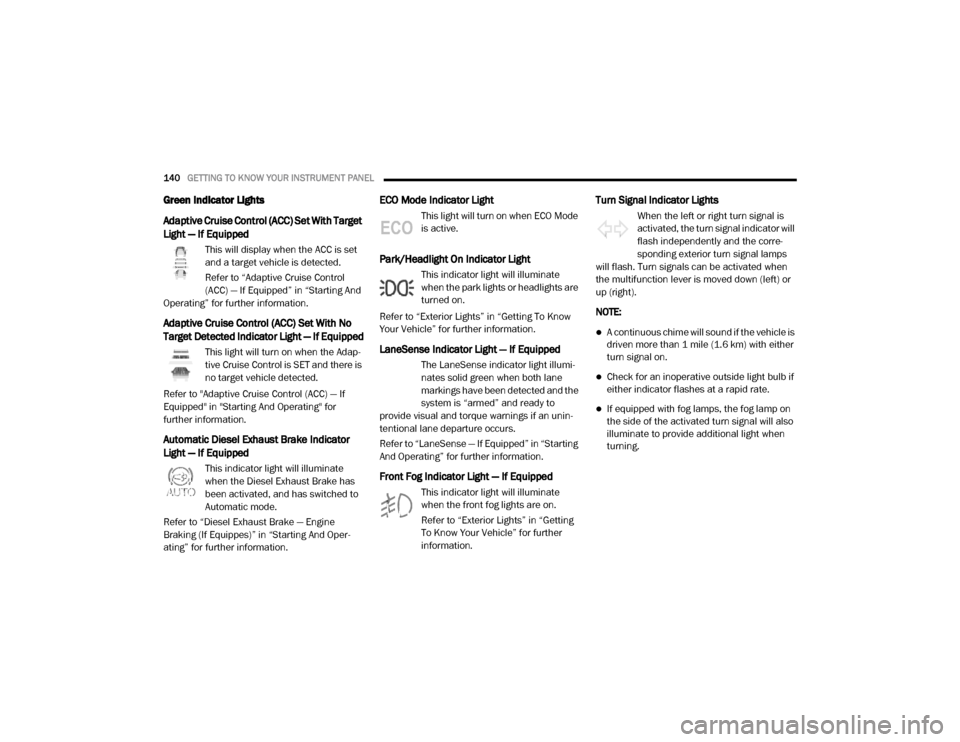
Green Indicator Lights
Adaptive Cruise Control (ACC) Set With Target
Light — If Equipped
This will display when the ACC is set
and a target vehicle is detected.
Refer to “Adaptive Cruise Control
(ACC) — If Equipped” in “Starting And
Operating” for further information.
Adaptive Cruise Control (ACC) Set With No
Target Detected Indicator Light — If Equipped
This light will turn on when the Adap -
tive Cruise Control is SET and there is
no target vehicle detected.
Refer to "Adaptive Cruise Control (ACC) — If
Equipped" in "Starting And Operating" for
further information.
Automatic Diesel Exhaust Brake Indicator
Light — If Equipped
This indicator light will illuminate
when the Diesel Exhaust Brake has
been activated, and has switched to
Automatic mode.
Refer to “Diesel Exhaust Brake — Engine
Braking (If Equippes)” in “Starting And Oper -
ating” for further information.
ECO Mode Indicator Light
This light will turn on when ECO Mode
is active.
Park/Headlight On Indicator Light
This indicator light will illuminate
when the park lights or headlights are
turned on.
Refer to “Exterior Lights” in “Getting To Know
Your Vehicle” for further information.
LaneSense Indicator Light — If Equipped
The LaneSense indicator light illumi -
nates solid green when both lane
markings have been detected and the
system is “armed” and ready to
provide visual and torque warnings if an unin -
tentional lane departure occurs.
Refer to “LaneSense — If Equipped” in “Starting
And Operating” for further information.
Front Fog Indicator Light — If Equipped
This indicator light will illuminate
when the front fog lights are on.
Refer to “Exterior Lights” in “Getting
To Know Your Vehicle” for further
information.
Turn Signal Indicator Lights
When the left or right turn signal is
activated, the turn signal indicator will
flash independently and the corre -
sponding exterior turn signal lamps
will flash. Turn signals can be activated when
the multifunction lever is moved down (left) or
up (right).
NOTE:
A continuous chime will sound if the vehicle is
driven more than 1 mile (1.6 km) with either
turn signal on.
Check for an inoperative outside light bulb if
either indicator flashes at a rapid rate.
If equipped with fog lamps, the fog lamp on
the side of the activated turn signal will also
illuminate to provide additional light when
turning.
20_DJD2_OM_EN_USC_t.book Page 140
Page 143 of 553

GETTING TO KNOW YOUR INSTRUMENT PANEL141
Cruise Control Set Indicator Light — If
Equipped
This indicator light will illuminate
when the cruise control is set to the
desired speed. Refer to “Speed
Control” in “Starting And Operating”
for further information.
White Indicator Lights
Adaptive Cruise Control (ACC) Ready Light —
If Equipped
This light will illuminate when the
vehicle equipped with Adaptive Cruise
Control (ACC) has been turned on but
not set.
Refer to “Adaptive Cruise Control (ACC) — If
Equipped” in “Starting And Operating” for
further information.
Cruise Control Ready Indicator
This indicator light will illuminate
when the cruise control is ready, but
not set. Refer to “Speed Control” in
“Starting And Operating” for further
information.
Hill Descent Control (HDC) Indicator Light — If
Equipped
This indicator shows when the Hill
Descent Control (HDC) feature is
turned on. The lamp will be on solid
when HDC is armed. HDC can only be
armed when the transfer case is in the “4WD
LOW” position and the vehicle speed is less
then 20 mph (32 km/h). If these conditions are
not met while attempting to use the HDC
feature, the HDC indicator light will flash on/off.
LaneSense Indicator Light — If Equipped
When the LaneSense system is ON,
but not armed, the LaneSense indi -
cator light illuminates solid white. This
occurs when only left, right, or neither
lane line has been detected. If a single lane line
is detected, the system is ready to provide only
visual warnings if an unintentional lane depar -
ture occurs on the detected lane line.
Refer to “LaneSense — If Equipped” in “Starting
And Operating” for further information.
Blue Indicator Lights
High Beam Indicator Light
This indicator light will illuminate to
indicate that the high beam head -
lights are on. With the low beams acti -
vated, push the multifunction lever
forward (toward the front of the vehicle) to turn
on the high beams. Pull the multifunction lever
rearward (toward the rear of the vehicle) to turn
off the high beams. If the high beams are off,
pull the lever toward you for a temporary high
beam on, "flash to pass" scenario.
ONBOARD DIAGNOSTIC SYSTEM — OBD II
Your vehicle is equipped with a sophisticated
Onboard Diagnostic system called OBD II. This
system monitors the performance of the emis -
sions, engine, and transmission control
systems. When these systems are operating
properly, your vehicle will provide excellent
performance and fuel economy, as well as
engine emissions well within current govern -
ment regulations.
If any of these systems require service, the OBD
II system will turn on the Malfunction Indicator
Light (MIL). It will also store diagnostic codes
and other information to assist your service
3
20_DJD2_OM_EN_USC_t.book Page 141
Page 155 of 553
SAFETY153
Traction Control System (TCS)
This system monitors the amount of wheel spin
of each of the driven wheels. If wheel spin is
detected, the Traction Control System (TCS)
may apply brake pressure to the spinning
wheel(s) and/or reduce engine power to provide
enhanced acceleration and stability. A feature
of the TCS, Brake Limited Differential (BLD),
functions similar to a limited slip differential
and controls the wheel spin across a driven
axle. If one wheel on a driven axle is spinning
faster than the other, the system will apply the
brake of the spinning wheel. This will allow more
engine power to be applied to the wheel that is
not spinning. BLD may remain enabled even if
TCS and Electronic Stability Control (ESC) are in
a reduced mode.
Trailer Sway Control (TSC)
Trailer Sway Control (TSC) uses sensors in the
vehicle to recognize an excessively swaying
trailer and will take the appropriate actions to
attempt to stop the sway. TSC will become
active automatically once an excessively
swaying trailer is recognized. NOTE:
TSC cannot stop all trailers from swaying.
Always use caution when towing a trailer and
follow the trailer tongue weight recommenda
-
tions. Refer to “Trailer Towing” in “Starting And
Operating” for further information.
When TSC is functioning, the “ESC Activation/
Malfunction Indicator Light” will flash, the
engine power may be reduced and you may feel
the brakes being applied to individual wheels to
attempt to stop the trailer from swaying. TSC is
disabled when the ESC system is in the “Partial
Off” or “Full Off” modes.
AUXILIARY DRIVING SYSTEMS
Blind Spot Monitoring (BSM) — If Equipped
The Blind Spot Monitoring (BSM) system uses
two radar-based sensors, located inside the tail -
lights, to detect highway licensable vehicles
(automobiles, trucks, motorcycles, etc.) that enter the blind spot zones from the rear/front/
side of the vehicle.
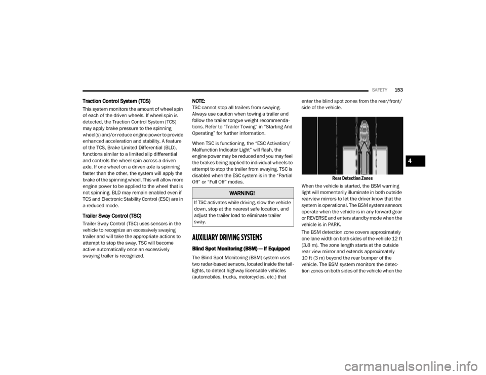
Rear Detection Zones
When the vehicle is started, the BSM warning
light will momentarily illuminate in both outside
rearview mirrors to let the driver know that the
system is operational. The BSM system sensors
operate when the vehicle is in any forward gear
or REVERSE and enters standby mode when the
vehicle is in PARK.
The BSM detection zone covers approximately
one lane width on both sides of the vehicle 12 ft
(3.8 m). The zone length starts at the outside
rear view mirror and extends approximately
10 ft (3 m) beyond the rear bumper of the
vehicle. The BSM system monitors the detec -
tion zones on both sides of the vehicle when the
WARNING!
If TSC activates while driving, slow the vehicle
down, stop at the nearest safe location, and
adjust the trailer load to eliminate trailer
sway.
4
20_DJD2_OM_EN_USC_t.book Page 153
Page 156 of 553

154SAFETY
vehicle speed reaches approximately 6 mph
(10 km/h) or higher and will alert the driver of
vehicles in these areas.
NOTE:
The BSM system DOES NOT alert the driver
about rapidly approaching vehicles that are
outside the detection zones.
The Blind Spot Monitoring (BSM) system may
experience drop outs (blinking on and off) of
the side mirror Warning Indicator lamps
when a motorcycle or any small object
remains at the side of the vehicle for
extended periods of time (more than a couple
of seconds).
The vehicle’s taillights, where the radar sensors
are located, must remain free of snow, ice, and
dirt/road contamination so that the BSM
system can function properly. Do not block the
taillights with foreign objects (bumper stickers,
bicycle racks, etc.).
Radar Sensor Locations
If the system detects degraded performance
due to contamination or foreign objects, a
message will warn you of a blocked sensor and
the warning indicators in side view mirrors will
be on. The warning indicators will remain illumi -
nated until blockage clearing conditions are
met. First clear the taillights around the sensors
of the blockage. After removing the blockage,
the following procedure can be used to reset
the system, cycle the ignition from ON to OFF
and then back ON.
If the blockage message is still present after
cycling the ignition and driving in traffic, check
again for a blockage. The BSM system notifies the driver of objects in
the detection zones by illuminating the BSM
warning light located in the outside mirrors in
addition to sounding an audible (chime) alert
and reducing the radio volume. Refer to “Modes
Of Operation” in this section for further informa-
tion.
Warning Light Location
The BSM system monitors the detection zone
from three different entry points (side, rear,
front) while driving to see if an alert is neces -
sary. The BSM system will issue an alert during
these types of zone entries.
20_DJD2_OM_EN_USC_t.book Page 154
Page 159 of 553

SAFETY157
Modes Of Operation
Three selectable modes of operation are avail -
able in the Uconnect System.
Refer to “Uconnect Settings” in “Multimedia”
for further information.
Blind Spot Alert Lights Only
When operating in Blind Spot Alert mode, the
BSM system will provide a visual alert in the
appropriate side view mirror based on a
detected object. However, when the system is
operating in Rear Cross Path (RCP) mode, the
system will respond with both visual and
audible alerts when a detected object is
present. Whenever an audible alert is
requested, the radio is muted.
Blind Spot Alert Lights/Chime
When operating in Blind Spot Alert Lights/
Chime mode, the BSM system will provide a
visual alert in the appropriate side view mirror
based on a detected object. If the turn signal is
then activated, and it corresponds to an alert
present on that side of the vehicle, an audible
chime will also be sounded. Whenever a turn
signal and detected object are present on the
same side at the same time, both the visual and
audible alerts will be issued. In addition to the
audible alert the radio (if on) will also be muted. NOTE:
Whenever an audible alert is requested by the
BSM system, the radio is also muted.
When the system is in RCP, the system shall
respond with both visual and audible alerts
when a detected object is present. Whenever
an audible alert is requested, the radio is also
muted. Turn/hazard signal status is ignored;
the RCP state always requests the chime.
Blind Spot Alert Off
When the BSM system is turned off there will be
no visual or audible alerts from either the BSM
or RCP systems.
NOTE:
The BSM system will store the current operating
mode when the vehicle is shut off. Each time
the vehicle is started the previously stored
mode will be recalled and used.
Trailer Merge Assist
NOTE:
When Trailer Merge Assist is activated, Rear
Cross Path is disabled.
NOTE:
When a trailer with an electric brake is
connected to the vehicle, the instrument cluster
display will provide a menu to allow a selection
of the trailer type. There will be two options
provided: Conventional and Goose/Fifth Wheel.
Goose/Fifth Wheel Trailer is incompatible and
when selected, the BSM system will disable
until the trailer is disconnected. If the wrong
option is selected, the system can be reset by
either disconnecting and reconnecting the
trailer harness connector or disabling then
re-enabling the Blind Spot Monitoring System in
the customer settings in the Uconnect. This will
prompt the trailer selection menu again to allow
for the correct selection.
Trailer Merge Assist is a function of the Blind
Spot Monitoring (BSM) system that extends the
blind spot zone to work while pulling a trailer.
Trailer Merge Assist consists of three sub func
-
tions:Automatic Trailer Detection
Trailer Length Detection
Trailer Merge Warning
4
20_DJD2_OM_EN_USC_t.book Page 157