Outlets Ram 2500 2020 Owner's Manual
[x] Cancel search | Manufacturer: RAM, Model Year: 2020, Model line: 2500, Model: Ram 2500 2020Pages: 553, PDF Size: 21.99 MB
Page 5 of 553

3
Power Mirrors — If Equipped ...................... 45
Power Convex Mirror Switch —
If Equipped ................................................... 46 Trailer Towing Mirrors — If Equipped ......... 46
Heated Mirrors — If Equipped ..................... 47
Tilt Side Mirrors In Reverse —
If Equipped ................................................... 47 Power Folding Outside Mirrors For
Standard And Trailer Tow — If Equipped .... 47 Illuminated Vanity Mirror — If Equipped ..... 48
EXTERIOR LIGHTS.................................................49
Multifunction Lever ...................................... 49
Headlight Switch .......................................... 49
Daytime Running Lights (DRLs) —
If Equipped ................................................... 49 High/Low Beam Switch ............................... 50
Automatic High Beam Headlamp Control —
If Equipped ................................................... 50 Flash-To-Pass ............................................... 51
Automatic Headlights — If Equipped ......... 51
Directional LED Headlamp System — If
Equipped ...................................................... 51 Parking Lights And Panel Lights ................. 51
Headlights On With Wipers (Available With
Automatic Headlights Only) ......................... 51 Headlight Delay ............................................ 51
Lights-On Reminder ..................................... 52 Front Fog Lights — If Equipped .................. 52
Turn Signals ................................................ 52
Lane Change Assist — If Equipped ............. 52
Cargo Lights/Trailer Spotter Lights With
Bed Lights — If Equipped............................. 52 Battery Saver ............................................... 53
INTERIOR LIGHTS ................................................ 53
Courtesy Lights ............................................ 53
Illuminated Entry ......................................... 55
WINDSHIELD WIPERS AND WASHERS............. 55
Windshield Wipers ....................................... 55
Rain Sensing Wipers — If Equipped ........... 56
CLIMATE CONTROLS ........................................... 57
Manual Climate Control Overview .............. 57
Automatic Climate Control Overview .......... 61
Climate Control Functions........................... 68
Automatic Temperature Control (ATC) ....... 68
Operating Tips ............................................. 69
WINDOWS ............................................................ 70
Power Windows ........................................... 70
Wind Buffeting ............................................ 72
POWER SUNROOF — IF EQUIPPED .................... 72
Single Pane Power Sunroof —
If Equipped ................................................... 72
HOOD .................................................................... 74
To Open The Hood ...................................... 74
To Close The Hood ....................................... 75 TAILGATE ...............................................................75
Opening ........................................................ 75
Closing.......................................................... 75
Bed Step — If Equipped ............................... 75
GARAGE DOOR OPENER — IF EQUIPPED ..........76
Before You Begin Programming
HomeLink® .................................................. 77 Canadian/Gate Operator Programming..... 79
Using HomeLink®........................................ 80
Security ........................................................ 80
Troubleshooting Tips ................................... 80
General Information .................................... 81
INTERNAL EQUIPMENT ........................................82
Storage ......................................................... 82
Cupholders .................................................. 87
Electrical Power Outlets .............................. 88
Power Inverter — If Equipped ..................... 90
Wireless Charging Pad — If Equipped ....... 91
Overhead Sunglass Storage ....................... 92
PICKUP BOX .........................................................92
Cargo Camera — If Equipped ...................... 93
RAMBOX — IF EQUIPPED .....................................94
RamBox Integrated Box Side Storage
Bins............................................................... 95 RamBox Safety Warning ............................. 96
Bed Divider — If Equipped ........................... 96
Bed Rail Tie-Down System —
If Equipped .................................................. 98
20_DJD2_OM_EN_USC_t.book Page 3
Page 61 of 553
GETTING TO KNOW YOUR VEHICLE59
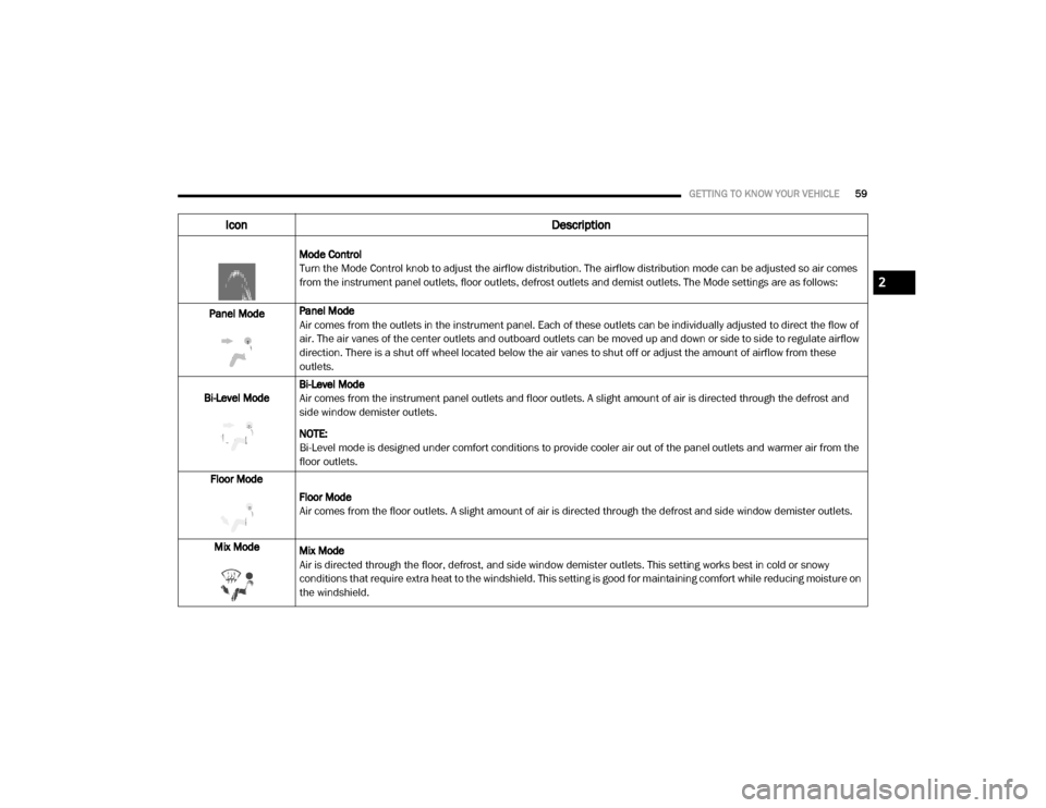
Mode Control
Turn the Mode Control knob to adjust the airflow distribution. The airflow distribution mode can be adjusted so air comes
from the instrument panel outlets, floor outlets, defrost outlets and demist outlets. The Mode settings are as follows:
Panel Mode Panel Mode
Air comes from the outlets in the instrument panel. Each of these outlets can be individually adjusted to direct the flow of
air. The air vanes of the center outlets and outboard outlets can be moved up and down or side to side to regulate airflow
direction. There is a shut off wheel located below the air vanes to shut off or adjust the amount of airflow from these
outlets.
Bi-Level Mode Bi-Level Mode
Air comes from the instrument panel outlets and floor outlets. A slight amount of air is directed through the defrost and
side window demister outlets.
NOTE:
Bi-Level mode is designed under comfort conditions to provide cooler air out of the panel outlets and warmer air from the
floor outlets.
Floor Mode
Floor Mode
Air comes from the floor outlets. A slight amount of air is directed through the defrost and side window demister outlets.
Mix Mode Mix Mode
Air is directed through the floor, defrost, and side window demister outlets. This setting works best in cold or snowy
conditions that require extra heat to the windshield. This setting is good for maintaining comfort while reducing moisture on
the windshield.
Icon Description
2
20_DJD2_OM_EN_USC_t.book Page 59
Page 62 of 553

60GETTING TO KNOW YOUR VEHICLE
Front Defrost Setting
Turn the Mode Control knob to the Front Defrost mode setting. Air comes from the windshield and side window demist
outlets. When the defrost button is selected, the blower level may increase. Use Defrost mode with maximum temperature
settings for best windshield and side window defrosting and defogging.
Rear Defrost Button
Push and release the Rear Defrost button to turn on the rear window defroster and the heated outside mirrors (if
equipped). The Rear Defrost indicator illuminates when the rear window defroster is on. The rear window defroster
automatically turns off after 15 minutes.
Climate Control OFF
To turn the Climate Controls off, turn the Blower Control knob to the O (off) position.
Icon Description
20_DJD2_OM_EN_USC_t.book Page 60
Page 66 of 553

64GETTING TO KNOW YOUR VEHICLE
Faceplate Auto Button
Touchscreen Auto Button AUTO
Press and release this button on the touchscreen, or push the button on the faceplate, to change the current setting. The
AUTO indicator illuminates when AUTO is on. This feature automatically controls the interior cabin temperature by adjusting
airflow distribution and amount. Toggling this function will cause the system to switch between manual mode and
automatic modes. Refer to “Automatic Operation” within this section for more information.
Front Defrost Button
Press and release the Front Defrost button on the touchscreen, or push and release the button on the faceplate, to change
the current airflow setting to Defrost mode. The Front Defrost indicator illuminates when Front Defrost is on. Air comes from
the windshield and side window demist outlets. When the defrost button is selected, the blower level may increase. Use
Defrost mode with maximum temperature settings for best windshield and side window defrosting and defogging. When
toggling the front defrost mode button, the climate system will return to previous setting.
Rear Defrost Button
Push and release the Rear Defrost button on the touchscreen, or push and release the button on the faceplate, to turn on
the rear window defroster and the heated outside mirrors (if equipped). The Rear Defrost indicator illuminates when the
rear window defroster is on. The rear window defroster automatically turns off after 15 minutes.
Icon
Description
20_DJD2_OM_EN_USC_t.book Page 64
Page 68 of 553
66GETTING TO KNOW YOUR VEHICLE
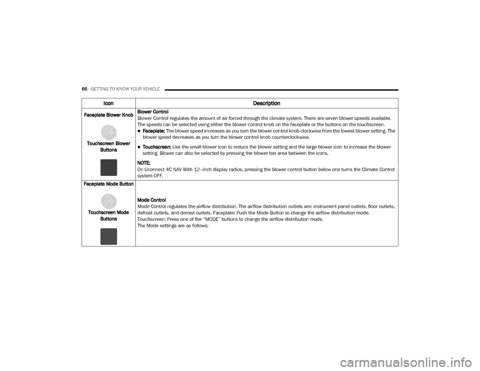
Faceplate Blower Knob
Touchscreen Blower Buttons Blower Control
Blower Control regulates the amount of air forced through the climate system. There are seven blower speeds available.
The speeds can be selected using either the blower control knob on the faceplate or the buttons on the touchscreen.
Faceplate: The blower speed increases as you turn the blower control knob clockwise from the lowest blower setting. The
blower speed decreases as you turn the blower control knob counterclockwise.
Touchscreen:
Use the small blower icon to reduce the blower setting and the large blower icon to increase the blower
setting. Blower can also be selected by pressing the blower bar area between the icons.
NOTE:
On Uconnect 4C NAV With 12–inch display radios, pressing the blower control button below one turns the Climate Control
system OFF.
Faceplate Mode Button
Touchscreen Mode Buttons Mode Control
Mode Control regulates the airflow distribution. The airflow distribution outlets are: instrument panel outlets, floor outlets,
defrost outlets, and demist outlets. Faceplate: Push the Mode Button to change the airflow distribution mode.
Touchscreen: Press one of the “MODE” buttons to change the airflow distribution mode.
The Mode settings are as follows:
Icon
Description
20_DJD2_OM_EN_USC_t.book Page 66
Page 69 of 553
GETTING TO KNOW YOUR VEHICLE67
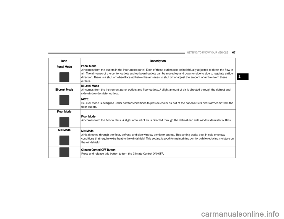
Panel ModePanel Mode
Air comes from the outlets in the instrument panel. Each of these outlets can be individually adjusted to direct the flow of
air. The air vanes of the center outlets and outboard outlets can be moved up and down or side to side to regulate airflow
direction. There is a shut off wheel located below the air vanes to shut off or adjust the amount of airflow from these
outlets.
Bi-Level Mode Bi-Level Mode
Air comes from the instrument panel outlets and floor outlets. A slight amount of air is directed through the defrost and
side window demister outlets.
NOTE:
Bi-Level mode is designed under comfort conditions to provide cooler air out of the panel outlets and warmer air from the
floor outlets.
Floor Mode
Floor Mode
Air comes from the floor outlets. A slight amount of air is directed through the defrost and side window demister outlets.
Mix Mode Mix Mode
Air is directed through the floor, defrost, and side window demister outlets. This setting works best in cold or snowy
conditions that require extra heat to the windshield. This setting is good for maintaining comfort while reducing moisture on
the windshield.
Climate Control OFF Button
Press and release this button to turn the Climate Control ON/OFF.
Icon Description
2
20_DJD2_OM_EN_USC_t.book Page 67
Page 70 of 553
68GETTING TO KNOW YOUR VEHICLE
Climate Control Functions
A/C (Air Conditioning)
The Air Conditioning (A/C) button allows the
operator to manually activate or deactivate the
air conditioning system. When the air condi -
tioning system is turned on, cool dehumidified
air will flow through the outlets into the cabin.
For improved fuel economy, press the A/C
button to turn off the air conditioning and manu -
ally adjust the blower and airflow mode settings.
Also, make sure to select only Panel, Bi-Level, or
Floor modes.
NOTE:
For Manual Climate Controls, if the system is
in Mix, Floor or Defrost Mode, the A/C can be
turned off, but the A/C system shall remain
active to prevent fogging of the windows.
If fog or mist appears on the windshield or
side glass, select Defrost mode, and increase
blower speed if needed.
If your air conditioning performance seems
lower than expected, check the front of the
A/C condenser (located in front of the radi -
ator), for an accumulation of dirt or insects. Clean with a gentle water spray from the front
of the radiator and through the condenser.
MAX A/C
MAX A/C sets the control for maximum cooling
performance.
Press and release to toggle between MAX A/C
and the prior settings. The button illuminates
when MAX A/C is on.
In MAX A/C, the blower level and mode position
can be adjusted to desired user settings.
Pressing other settings will cause the MAX A/C
operation to switch to the selected setting and
MAX A/C to exit.
Recirculation
In cold weather, use of Recirculation mode may
lead to excessive window fogging. The Recircu -
lation feature may be unavailable (button on
the touchscreen greyed out) if conditions exist
that could create fogging on the inside of the
windshield.
On systems with Manual Climate Controls, if
equipped, the Recirculation mode is not
allowed in Defrost mode to improve window
clearing operation. Recirculation is disabled
automatically if this mode is selected. Attempting to use Recirculation while in this
mode causes the LED in the control button to
blink and then turns off.
Automatic Temperature Control (ATC)
Automatic Operation
1. Push the AUTO button on the faceplate, or the AUTO button on the touchscreen on the
Automatic Temperature Control (ATC)
Panel.
2. Next, adjust the temperature you would like the system to maintain by adjusting the
driver and passenger temperature control
buttons. Once the desired temperature is
displayed, the system will achieve and auto -
matically maintain that comfort level.
3. When the system is set up for your comfort level, it is not necessary to change the
settings. You will experience the greatest
efficiency by simply allowing the system to
function automatically.
20_DJD2_OM_EN_USC_t.book Page 68
Page 85 of 553
GETTING TO KNOW YOUR VEHICLE83
Pull on the upper handle on the front of the
armrest to raise the cover. The upper storage
area contains a USB power outlet located at the
rear of the area that can be used to power small
electrical devices, refer to “Electrical Power
Outlets” in this section for further information.
With the upper lid closed, pull on the lower
handle to open the lower storage bin. The lower
bin contains a power inverter outlet located in
the forward portion of the lower bin. There is
also a “fill line” located along the rear inside
wall of the lower bin. Contents above the “fill
line” may interfere with cupholder placement if
equipped with a premium center console.
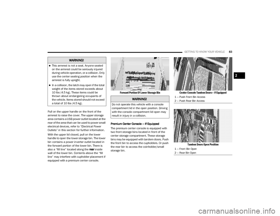
Forward Portion Of Lower Storage Bin
Premium Center Console — If Equipped
The premium center console is equipped with
two front storage bins located in front of the
center storage compartment. These storage
bins may be equipped with tandem doors. Push
the front bin to access the cupholders. Or push
the rear bin to access the coinholder/small
storage bin.
Center Console Tandem Doors— If Equipped
Tandem Doors Open Position
WARNING!
This armrest is not a seat. Anyone seated
on the armrest could be seriously injured
during vehicle operation, or a collision. Only
use the center seating position when the
armrest is fully upright.
In a collision, the latch may open if the total
weight of the items stored exceeds about
10 lbs (4.5 kg). These items could be
thrown about endangering occupants of
the vehicle. Items stored should not exceed
a total of 10 lbs (4.5 kg).
WARNING!
Do not operate this vehicle with a console
compartment lid in the open position. Driving
with the console compartment lid open may
result in injury in a collision.
1 — Push Front Bin Access
2 — Push Rear Bin Access
1 — Front Bin Open
2 — Rear Bin Open
2
20_DJD2_OM_EN_USC_t.book Page 83
Page 90 of 553
88GETTING TO KNOW YOUR VEHICLE
(Continued)
Vehicles Equipped With 40/20/40 Seats
The cupholders are located on the backside of
the center portion of the front seat (20). Fold
down the center section of the front seat to gain
access to the cupholders.
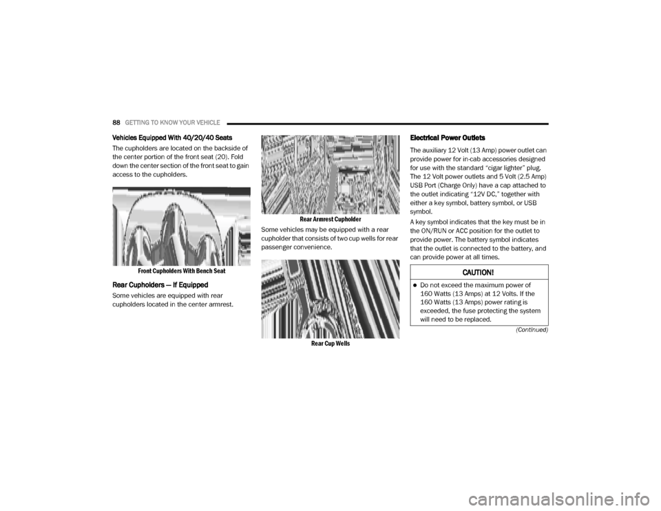
Front Cupholders With Bench Seat
Rear Cupholders — If Equipped
Some vehicles are equipped with rear
cupholders located in the center armrest.
Rear Armrest Cupholder
Some vehicles may be equipped with a rear
cupholder that consists of two cup wells for rear
passenger convenience.
Rear Cup Wells
Electrical Power Outlets
The auxiliary 12 Volt (13 Amp) power outlet can
provide power for in-cab accessories designed
for use with the standard “cigar lighter” plug.
The 12 Volt power outlets and 5 Volt (2.5 Amp)
USB Port (Charge Only) have a cap attached to
the outlet indicating “12V DC,” together with
either a key symbol, battery symbol, or USB
symbol.
A key symbol indicates that the key must be in
the ON/RUN or ACC position for the outlet to
provide power. The battery symbol indicates
that the outlet is connected to the battery, and
can provide power at all times.
CAUTION!
Do not exceed the maximum power of
160 Watts (13 Amps) at 12 Volts. If the
160 Watts (13 Amps) power rating is
exceeded, the fuse protecting the system
will need to be replaced.
20_DJD2_OM_EN_USC_t.book Page 88
Page 91 of 553
GETTING TO KNOW YOUR VEHICLE89
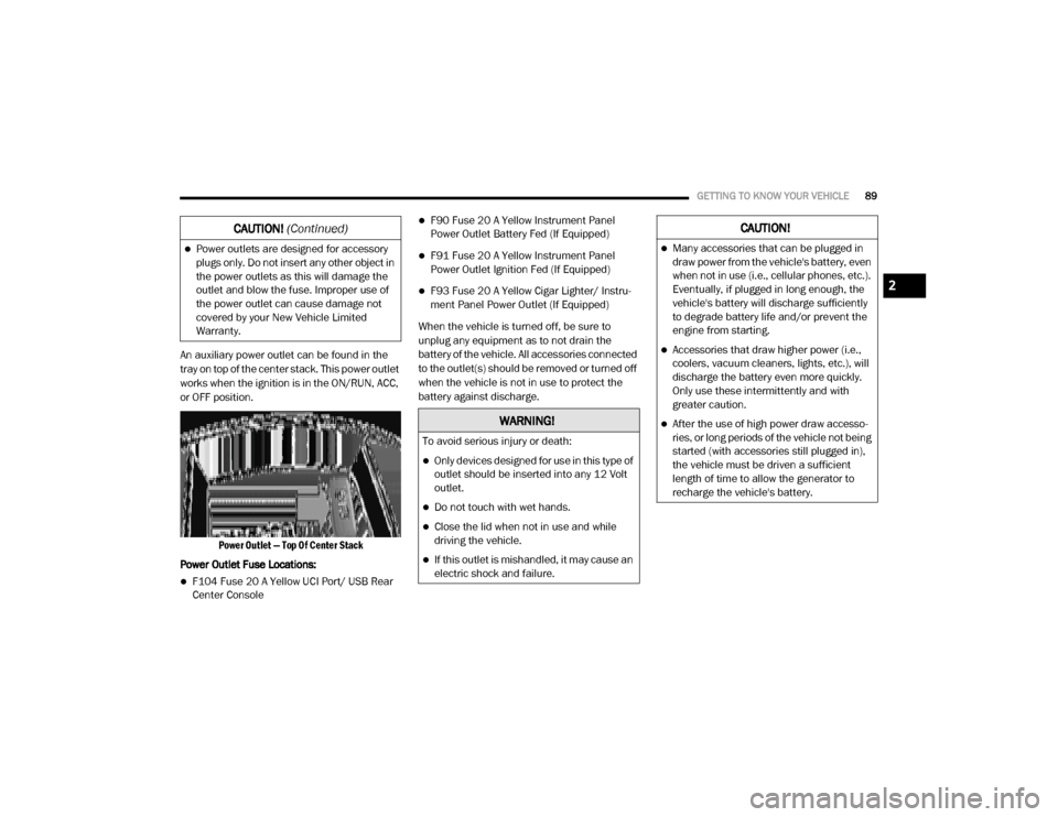
An auxiliary power outlet can be found in the
tray on top of the center stack. This power outlet
works when the ignition is in the ON/RUN, ACC,
or OFF position.
Power Outlet — Top Of Center Stack
Power Outlet Fuse Locations:
F104 Fuse 20 A Yellow UCI Port/ USB Rear
Center Console
F90 Fuse 20 A Yellow Instrument Panel
Power Outlet Battery Fed (If Equipped)
F91 Fuse 20 A Yellow Instrument Panel
Power Outlet Ignition Fed (If Equipped)
F93 Fuse 20 A Yellow Cigar Lighter/ Instru -
ment Panel Power Outlet (If Equipped)
When the vehicle is turned off, be sure to
unplug any equipment as to not drain the
battery of the vehicle. All accessories connected
to the outlet(s) should be removed or turned off
when the vehicle is not in use to protect the
battery against discharge.
Power outlets are designed for accessory
plugs only. Do not insert any other object in
the power outlets as this will damage the
outlet and blow the fuse. Improper use of
the power outlet can cause damage not
covered by your New Vehicle Limited
Warranty.
CAUTION! (Continued)
WARNING!
To avoid serious injury or death:
Only devices designed for use in this type of
outlet should be inserted into any 12 Volt
outlet.
Do not touch with wet hands.
Close the lid when not in use and while
driving the vehicle.
If this outlet is mishandled, it may cause an
electric shock and failure.
CAUTION!
Many accessories that can be plugged in
draw power from the vehicle's battery, even
when not in use (i.e., cellular phones, etc.).
Eventually, if plugged in long enough, the
vehicle's battery will discharge sufficiently
to degrade battery life and/or prevent the
engine from starting.
Accessories that draw higher power (i.e.,
coolers, vacuum cleaners, lights, etc.), will
discharge the battery even more quickly.
Only use these intermittently and with
greater caution.
After the use of high power draw accesso -
ries, or long periods of the vehicle not being
started (with accessories still plugged in),
the vehicle must be driven a sufficient
length of time to allow the generator to
recharge the vehicle's battery.
2
20_DJD2_OM_EN_USC_t.book Page 89