radio controls Ram 2500 2020 Owner's Manual
[x] Cancel search | Manufacturer: RAM, Model Year: 2020, Model line: 2500, Model: Ram 2500 2020Pages: 553, PDF Size: 21.99 MB
Page 11 of 553

9
TECHNICAL SPECIFICATIONS
IDENTIFICATION DATA ...................................... 444Vehicle Identification Number ................. 444
BRAKE SYSTEM ................................................ 444
Hydraulic Brake Assist — If Equipped .......444
WHEEL AND TIRE TORQUE
SPECIFICATIONS ................................................ 444
Torque Specifications ................................444
FUEL REQUIREMENTS — GAS ENGINE ............ 446
6.4L Engine ................................................446
Reformulated Gasoline .............................446
Materials Added To Fuel ...........................446
Gasoline/Oxygenate Blends......................446
Do Not Use E-85 In Non-Flex Fuel
Vehicles ......................................................447 CNG And LP Fuel System Modifications ...447
MMT In Gasoline ........................................447
Fuel System Cautions ................................447
Carbon Monoxide Warnings ......................448
FUEL REQUIREMENTS – DIESEL ENGINE ...... 448
Fuel Specifications ...................................448
Biodiesel Fuel Requirements ....................449
FLUID CAPACITIES — GAS ENGINE .................. 451
FLUID CAPACITIES — DIESEL ENGINE............. 451
FLUIDS AND LUBRICANTS — GAS ENGINE ..... 452
Engine ........................................................ 452
Chassis .......................................................454 FLUIDS AND LUBRICANTS — DIESEL
ENGINE ................................................................ 454
Engine ........................................................ 454
Chassis ....................................................... 457
MULTIMEDIA
UCONNECT SYSTEMS .......................................458
CYBERSECURITY ............................................... 458
UCONNECT SETTINGS ........................................ 459
Uconnect 3 Settings .................................. 459
Uconnect 4/4C/4C NAV Settings ............. 473
Uconnect 4C NAV With 12-inch Display
Settings ...................................................... 493
SAFETY AND GENERAL INFORMATION ........... 511
Safety Guidelines....................................... 511
UCONNECT 3 WITH 5-INCH DISPLAY ..............512
Introduction................................................ 512
Radio Mode ................................................ 513
Media Mode ............................................... 516
Phone Mode ............................................... 518
STEERING WHEEL AUDIO CONTROLS — IF
EQUIPPED ...........................................................525
Radio Operation ......................................... 525
Media Mode ............................................... 525
IPOD®/USB/MP3 CONTROL —
IF EQUIPPED ....................................................... 525 RADIO OPERATION AND MOBILE PHONES.... 527
Regulatory And Safety Information .......... 527
VOICE RECOGNITION QUICK TIPS .................. 529
Introducing Uconnect ................................ 529
Get Started................................................. 529
Basic Voice Commands ............................ 529
Radio .......................................................... 530
Media ......................................................... 530
Phone ......................................................... 531
Voice Text Reply — If Equipped ................. 531
Climate (4C/4C NAV)................................. 532
Navigation (4C NAV) .................................. 532
Siri® Eyes Free — If Equipped ................. 532
Using Do Not Disturb ................................ 532
Android Auto™ — If Equipped .................. 533
Apple CarPlay® — If Equipped ................. 533
General Information .................................. 534
Additional Information............................... 534
CUSTOMER ASSISTANCE
SUGGESTIONS FOR OBTAINING SERVICE FOR
YOUR VEHICLE .................................................. 536
Prepare For The Appointment .................. 536
Prepare A List............................................. 536
Be Reasonable With Requests ................. 536
20_DJD2_OM_EN_USC_t.book Page 9
Page 30 of 553
28GETTING TO KNOW YOUR VEHICLE
NOTE:
The key fob may not be able to be detected by
the vehicle Keyless Enter-N-Go system if it is
located next to a mobile phone, laptop or other
electronic device; these devices may block the
key fob’s wireless signal and prevent the
Keyless Enter-N-Go system from starting the
vehicle.
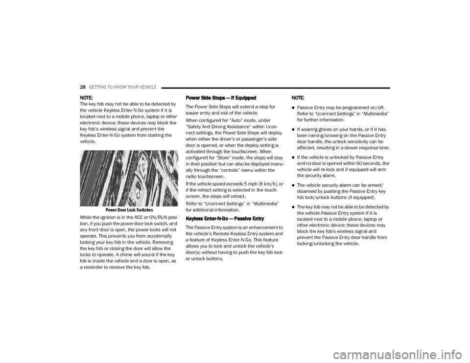
Power Door Lock Switches
While the ignition is in the ACC or ON/RUN posi -
tion, if you push the power door lock switch, and
any front door is open, the power locks will not
operate. This prevents you from accidentally
locking your key fob in the vehicle. Removing
the key fob or closing the door will allow the
locks to operate. A chime will sound if the key
fob is inside the vehicle and a door is open, as
a reminder to remove the key fob.Power Side Steps — If Equipped
The Power Side Steps will extend a step for
easier entry and exit of the vehicle.
When configured for “Auto” mode, under
“Safety And Driving Assistance” within Ucon -
nect settings, the Power Side Steps will deploy
when either the driver’s or passenger’s side
door is opened, or when the deploy setting is
activated through the touchscreen. When
configured for “Store” mode, the steps will stay
in their position but can also be deployed manu -
ally through the “controls” menu within the
radio touchscreen.
If the vehicle speed exceeds 5 mph (8 km/h), or
if the retract setting is selected in the touch -
screen, the steps will retract.
Refer to “Uconnect Settings” in “Multimedia”
for additional information.
Keyless Enter-N-Go — Passive Entry
The Passive Entry system is an enhancement to
the vehicle’s Remote Keyless Entry system and
a feature of Keyless Enter-N-Go. This feature
allows you to lock and unlock the vehicle’s
door(s) without having to push the key fob lock
or unlock buttons. NOTE:
Passive Entry may be programmed on/off.
Refer to “Uconnect Settings” in “Multimedia”
for further information.
If wearing gloves on your hands, or if it has
been raining/snowing on the Passive Entry
door handle, the unlock sensitivity can be
affected, resulting in a slower response time.
If the vehicle is unlocked by Passive Entry
and no door is opened within 60 seconds, the
vehicle will re-lock and if equipped will arm
the security alarm.
The vehicle security alarm can be armed/
disarmed by pushing the Passive Entry key
fob lock/unlock buttons (if equipped).
The key fob may not be able to be detected by
the vehicle Passive Entry system if it is
located next to a mobile phone, laptop or
other electronic device; these devices may
block the key fob's wireless signal and
prevent the Passive Entry door handle from
locking/unlocking the vehicle.
20_DJD2_OM_EN_USC_t.book Page 28
Page 41 of 553
GETTING TO KNOW YOUR VEHICLE39
Ventilated Seats — If Equipped
Front Ventilated Seats
Located in the seat cushion are small fans that
draw the air from the passenger compartment
and move air through fine perforations in the
seat cover to help keep the driver and front
passenger cooler in higher ambient tempera -
tures. The fans operate at three speeds, HI,
MED and LO.
The front ventilated seats control buttons are
located on the center instrument panel below
the touchscreen, and are also located within the
climate or controls screen of the touchscreen.
NOTE:
If the vehicle is equipped with a 12-inch radio,
there will only be control buttons through the
touchscreen.
Press the ventilated seat button once to
choose HI.
Press the ventilated seat button a second
time to choose MED.
Press the ventilated seat button a third
time to choose LO.
Press the ventilated seat button a fourth
time to turn the ventilation off.
NOTE:
The engine must be running for the ventilated
seats to operate.
Vehicles Equipped With Remote Start
On models that are equipped with remote start,
the driver’s seat can be programmed to come
on during a remote start.
This feature can be programmed through the
Uconnect system. Refer to “Uconnect Settings”
in “Multimedia” for further information.
HEAD RESTRAINTS
Head restraints are designed to reduce the risk
of injury by restricting head movement in the
event of a rear impact. Head restraints should
be adjusted so that the top of the head restraint
is located above the top of your ear. NOTE:
Do not reverse the head restraints (making the
rear of the head restraint face forward) in an
attempt to gain additional clearance to the back
of your head.
WARNING!
All occupants, including the driver, should
not operate a vehicle or sit in a vehicle’s
seat until the head restraints are placed in
their proper positions in order to minimize
the risk of neck injury in the event of a
crash.
Head restraints should never be adjusted
while the vehicle is in motion. Driving a
vehicle with the head restraints improperly
adjusted or removed could cause serious
injury or death in the event of a collision.
2
20_DJD2_OM_EN_USC_t.book Page 39
Page 59 of 553
GETTING TO KNOW YOUR VEHICLE57
NOTE:
The Rain Sensing feature will not operate
when the wiper switch is in the low or
high-speed position.
The Rain Sensing feature may not function
properly when ice, or dried salt water is
present on the windshield.
Use of Rain-X or products containing wax or
silicone may reduce Rain Sensing perfor -
mance.
The Rain Sensing system has protection
features for the wiper blades and arms, and will
not operate under the following conditions:
Low Ambient Temperature — When the igni-
tion is first placed in the ON position, the Rain
Sensing system will not operate until the
wiper switch is moved, vehicle speed is
greater than 0 mph (0 km/h), or the outside
temperature is greater than 32°F (0°C).
Transmission In NEUTRAL Position — When
the ignition is ON, and the transmission is in
the NEUTRAL position, the Rain Sensing
system will not operate until the wiper switch
is moved, vehicle speed is greater than
5 mph (8 km/h), or the gear selector is
moved out of the NEUTRAL position.
Remote Start Mode Inhibit — On vehicles
equipped with Remote Starting system, Rain
Sensing wipers are not operational when the
vehicle is in the remote start mode. Once the
operator is in the vehicle and has placed the
ignition switch in the RUN position, Rain
Sensing wiper operation can resume, if it has
been selected, and no other inhibit condi -
tions (mentioned previously) exist.
CLIMATE CONTROLS
The Climate Control system allows you to regu -
late the temperature, air flow, and direction of
air circulating throughout the vehicle. The
controls are located on the touchscreen (if
equipped), on the sides of the touchscreen, or
on the instrument panel below the radio.
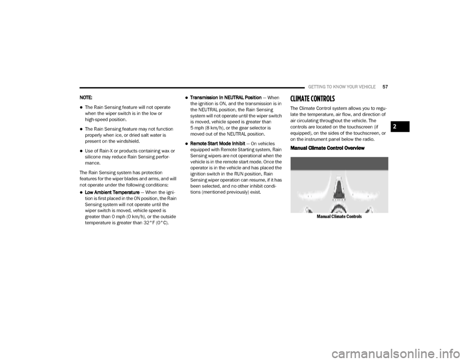
Manual Climate Control Overview
Manual Climate Controls
2
20_DJD2_OM_EN_USC_t.book Page 57
Page 476 of 553
474MULTIMEDIA
Display
After pressing the Display button on the touchscreen, the following settings will be available:
Setting Name Selectable Options
Display ModeAutoManual
NOTE:
When Auto or Manual is selected for the Display Mode, the usage of the Parade Mode feature will cause the radio to activate the Display Brightness
Day control even though the headlights are on. Display Brightness With Headlights ON –+
NOTE:
To make changes to the "Display Brightness With Headlights ON" setting, the headlights must be on and the interior dimmer switch must not be in
the "party" or "parade" position. Display Brightness With Headlights OFF –+
NOTE:
To make changes to the "Display Brightness With Headlights OFF" setting, the headlights must be off and the interior dimmer switch must not be in
the "party" or "parade" position. Touchscreen Beep OnOff
Controls Screen Time-Out — If Equipped OnOff
Fuel Saver Display in Cluster — If Equipped OnOff
NOTE:
When selected, the system displays fuel saver mode in the instrument cluster. Navigation Next Turn Pop-ups Displayed In Cluster — If Equipped On
Off
Phone Pop-ups Displayed in Cluster — If Equipped On
Off
20_DJD2_OM_EN_USC_t.book Page 474
Page 520 of 553
518MULTIMEDIA
Bluetooth® Mode
Bluetooth® Streaming Audio (BTSA) or Blue -
tooth® Mode is entered by pairing a Bluetooth®
device containing music to the Uconnect
system.
Before proceeding, the Bluetooth® device must
be paired with the Uconnect Phone to communi -
cate with the Uconnect system.
Refer to Phone Mode chapter in this manual for
pairing procedure.
Once the Bluetooth® device is paired to the
Uconnect system, push the MEDIA button
located on the faceplate. Once in Media Mode,
press the Source button on the touchscreen
and select the Bluetooth® button.
NOTE:
For mobile phone compatibility and pairing
instructions, please visit UconnectPhone.com.
AUX Mode
AUX Mode is entered by inserting a AUX device
using a stereo cable with a 3.5 mm audio jack
into the AUX port or by pushing the MEDIA button located on the faceplate. Once in Media
Mode, press the Source button on the touch
-
screen, and select the AUX button.
Inserting Auxiliary Device
Gently insert the Auxiliary device cable into the
AUX Port. If you insert an Auxiliary device with
the ignition on, the unit will switch to AUX mode
and begin to play when you insert the device
cable.
Controlling The Auxiliary Device
The control of the Auxiliary device (e.g.,
selecting playlists, play, fast forward, etc.)
cannot be provided by the radio; use the device
controls instead. Adjust the volume with the
VOLUME rotary knob or with the volume of the
attached device.
The radio unit is acting as the amplifier for audio
output from the Auxiliary device. Therefore, if
the volume control on the Auxiliary device is set
too low, there will be insufficient audio signal for
the radio unit to play the music on the device.
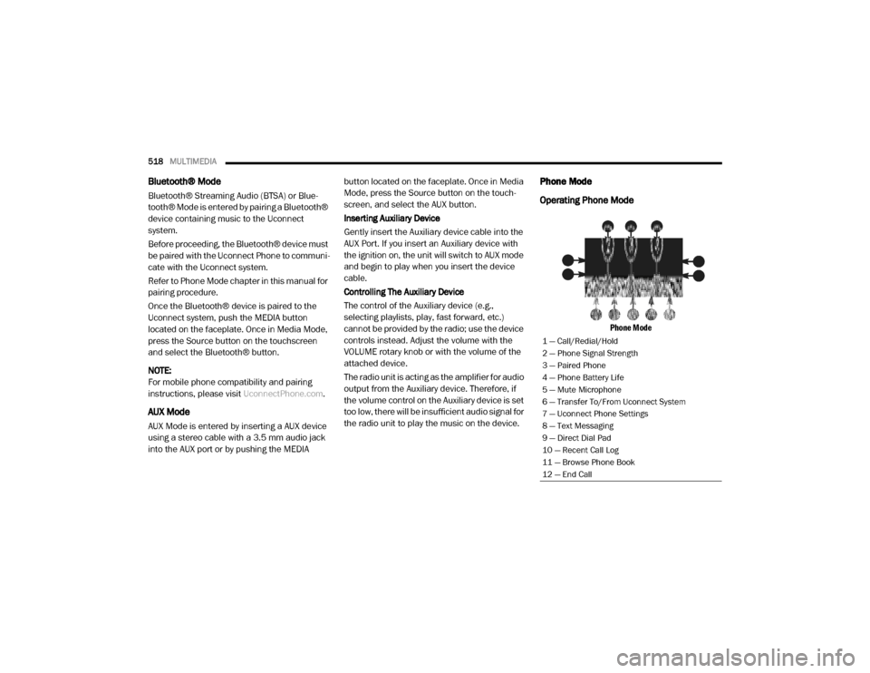
Phone Mode
Operating Phone Mode
Phone Mode
1 — Call/Redial/Hold
2 — Phone Signal Strength
3 — Paired Phone
4 — Phone Battery Life
5 — Mute Microphone
6 — Transfer To/From Uconnect System
7 — Uconnect Phone Settings
8 — Text Messaging
9 — Direct Dial Pad
10 — Recent Call Log
11 — Browse Phone Book
12 — End Call
20_DJD2_OM_EN_USC_t.book Page 518
Page 527 of 553
MULTIMEDIA525
STEERING WHEEL AUDIO CONTROLS — IF
EQUIPPED
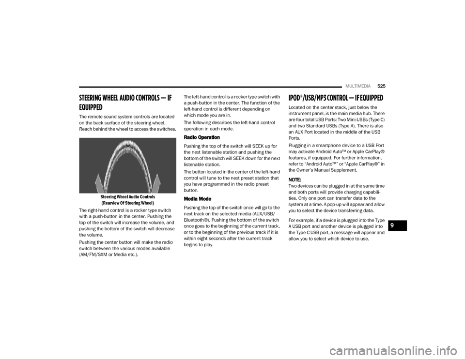
The remote sound system controls are located
on the back surface of the steering wheel.
Reach behind the wheel to access the switches.
Steering Wheel Audio Controls(Rearview Of Steering Wheel)
The right-hand control is a rocker type switch
with a push-button in the center. Pushing the
top of the switch will increase the volume, and
pushing the bottom of the switch will decrease
the volume.
Pushing the center button will make the radio
switch between the various modes available
(AM/FM/SXM or Media etc.). The left-hand control is a rocker type switch with
a push-button in the center. The function of the
left-hand control is different depending on
which mode you are in.
The following describes the left-hand control
operation in each mode.
Radio Operation
Pushing the top of the switch will SEEK up for
the next listenable station and pushing the
bottom of the switch will SEEK down for the next
listenable station.
The button located in the center of the left-hand
control will tune to the next preset station that
you have programmed in the radio preset
button.
Media Mode
Pushing the top of the switch once will go to the
next track on the selected media (AUX/USB/
Bluetooth®). Pushing the bottom of the switch
once goes to the beginning of the current track,
or to the beginning of the previous track if it is
within eight seconds after the current track
begins to play.
IPOD®/USB/MP3 CONTROL — IF EQUIPPED
Located on the center stack, just below the
instrument panel, is the main media hub. There
are four total USB Ports: Two Mini-USBs (Type C)
and two Standard USBs (Type A). There is also
an AUX Port located in the middle of the USB
Ports.
Plugging in a smartphone device to a USB Port
may activate Android Auto™ or Apple CarPlay®
features, if equipped. For further information,
refer to “Android Auto™” or “Apple CarPlay®” in
the Owner’s Manual Supplement.
NOTE:
Two devices can be plugged in at the same time
and both ports will provide charging capabili
-
ties. Only one port can transfer data to the
system at a time. A pop-up will appear and allow
you to select the device transferring data.
For example, if a device is plugged into the Type
A USB port and another device is plugged into
the Type C USB port, a message will appear and
allow you to select which device to use.
9
20_DJD2_OM_EN_USC_t.book Page 525
Page 529 of 553
MULTIMEDIA527
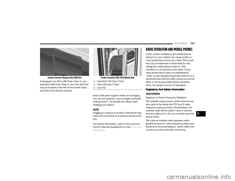
Center Console Charge Only USB Port
If equipped, two Mini-USB Ports (Type C), two
Standard USB Ports (Type A), and one AUX Port
may be located to the left of the center stack,
just below the climate controls.
Center Console USB/AUX Media Hub
Some USB ports support media and charging.
You can use features, such as Apple CarPlay®,
Android Auto™, Pandora® and others while
charging your phone.
NOTE:
Plugging in a phone or another USB device may
cause the connection to a previous device to be
lost.
For further information, refer to the Uconnect
Owner’s Manual Supplement or visit Uconnect-
Phone.com .
RADIO OPERATION AND MOBILE PHONES
Under certain conditions, the mobile phone
being on in your vehicle can cause erratic or
noisy performance from your radio. This condi -
tion may be lessened or eliminated by relo -
cating the mobile phone antenna. This
condition is not harmful to the radio. If your
radio performance does not satisfactorily
“clear” by the repositioning of the antenna, it is
recommended that the radio volume be turned
down or off during mobile phone operation
when not using Uconnect (if equipped).
Regulatory And Safety Information
USA/CANADA
Exposure to Radio Frequency Radiation
The radiated output power of the internal wire -
less radio is far below the FCC and IC radio
frequency exposure limits. Nevertheless, the
wireless radio will be used in such a manner
that the radio is 8 in (20 cm) or further from the
human body.
The internal wireless radio operates within
guidelines found in radio frequency safety stan -
dards and recommendations, which reflect the
consensus of the scientific community.
1 — Standard USB Type A Ports
2 — Mini-USB Type C Ports
3 — AUX Port
9
20_DJD2_OM_EN_USC_t.book Page 527