turn signal bulb Ram 2500 2020 Owner's Manual
[x] Cancel search | Manufacturer: RAM, Model Year: 2020, Model line: 2500, Model: Ram 2500 2020Pages: 553, PDF Size: 21.99 MB
Page 54 of 553
52GETTING TO KNOW YOUR VEHICLE
light switch is on, and then the headlight switch
is cycled off. Headlight delay can be canceled by
either turning the headlight switch on then off,
or by placing the ignition in the ON/RUN posi -
tion.
NOTE:
This feature can be programmed through the
Uconnect system. Refer to “Uconnect Settings”
in “Multimedia” for further information.
Lights-On Reminder
If the headlights, parking lights, or cargo lights
are left on after the ignition is placed in the OFF
position, a chime will sound and a message will
appear in the instrument cluster display when
the driver’s door is opened.
Front Fog Lights — If Equipped
To activate the front fog lights, turn on the
parking lights or low beam headlights and push
in the center of the headlight switch control
knob. Pushing the headlight switch control knob
a second time will turn the front fog lights off.
Front Fog Light Switch
Turn Signals
Move the multifunction lever up or down and
the arrows on each side of the instrument
cluster display will flash to show proper opera
-
tion of the front and rear turn signal lights.
NOTE:
If either light remains on and does not flash, or
there is a very fast flash rate, check for a defec -
tive outside light bulb. If an indicator fails to
light when the lever is moved, it would suggest
that the indicator bulb is defective.
Lane Change Assist — If Equipped
Tap the multifunction lever up or down once,
without moving beyond the detent, and the turn signal (right or left) will flash three times then
automatically turn off.
Cargo Lights/Trailer Spotter Lights With Bed
Lights — If Equipped
The cargo light and bed lights (if equipped) and
trailer spotter lights (if equipped) are turned on
by pushing the cargo lights button located on
the lower half of the headlight switch.
Cargo/Bed Lights Button On Headlight Switch
If the vehicle’s speed is 0 mph (0 km/h), these
lights can also be turned on using the switch
located just inside the pickup box, on the lower
part of the bed light lens. A telltale will illumi -
nate in the instrument cluster display when
these lights are on. Pushing the switch a second
time will turn the lights off.
20_DJD2_OM_EN_USC_t.book Page 52
Page 132 of 553
130GETTING TO KNOW YOUR INSTRUMENT PANEL
After a trip:
Check if any aftermarket equipment was
installed (additional lights, upfitter electrical
accessories, audio systems, alarms) and
review specifications if any (load and Ignition
Off Draw currents).
Evaluate the latest driving cycles (distance,
driving time and parking time).
The vehicle should have service performed if
the message is still present during consecu-
tive trips and the evaluation of the vehicle
and driving pattern did not help to identify the
cause.
WARNING LIGHTS AND MESSAGES
The warning/indicator lights will illuminate in
the instrument panel together with a dedicated
message and/or acoustic signal when appli -
cable. These indications are indicative and
precautionary and as such must not be consid -
ered as exhaustive. Always refer to the informa-
tion in this chapter in the event of a failure
indication. All active telltales will display first if
applicable. The system check menu may
appear different based upon equipment
options and current vehicle status. Some tell -
tales are optional and may not appear.
Red Warning Lights
Seat Belt Reminder Warning Light
This warning light indicates when the
driver or passenger seat belt is
unbuckled. When the ignition is first
placed in the ON/RUN or ACC/ON/
RUN position and if the driver’s seat belt is
unbuckled, a chime will sound and the light will
turn on. When driving, if the driver or front
passenger seat belt remains unbuckled, the
Seat Belt Reminder Light will flash or remain on
continuously and a chime will sound.
Refer to “Occupant Restraint Systems” in
“Safety” for further information.
Air Bag Warning Light
This warning light will illuminate to
indicate a fault with the air bag, and
will turn on for four to eight seconds
as a bulb check when the ignition is
placed in the ON/RUN or ACC/ON/RUN posi -
tion. This light will illuminate with a single chime
when a fault with the air bag has been detected,
it will stay on until the fault is cleared. If the light
is either not on during startup, stays on, or turns
on while driving, have the system inspected at
an authorized dealer as soon as possible.
Brake Warning Light
This warning light monitors various
brake functions, including brake fluid
level and parking brake application. If
the brake light turns on it may indi -
cate that the parking brake is applied, that the
brake fluid level is low, or that there is a
problem with the anti-lock brake system reser -
voir.
If the light remains on when the parking brake
has been disengaged, and the fluid level is at
the full mark on the master cylinder reservoir, it
indicates a possible brake hydraulic system
malfunction or that a problem with the Brake
Booster has been detected by the Anti-Lock
Brake System (ABS) / Electronic Stability
Control (ESC) system. In this case, the light will
remain on until the condition has been
corrected. If the problem is related to the brake
booster, the ABS pump will run when applying
the brake, and a brake pedal pulsation may be
felt during each stop.
The dual brake system provides a reserve
braking capacity in the event of a failure to a
portion of the hydraulic system. A leak in either
half of the dual brake system is indicated by the
Brake Warning Light, which will turn on when
20_DJD2_OM_EN_USC_t.book Page 130
Page 142 of 553
140GETTING TO KNOW YOUR INSTRUMENT PANEL
Green Indicator Lights
Adaptive Cruise Control (ACC) Set With Target
Light — If Equipped
This will display when the ACC is set
and a target vehicle is detected.
Refer to “Adaptive Cruise Control
(ACC) — If Equipped” in “Starting And
Operating” for further information.
Adaptive Cruise Control (ACC) Set With No
Target Detected Indicator Light — If Equipped
This light will turn on when the Adap -
tive Cruise Control is SET and there is
no target vehicle detected.
Refer to "Adaptive Cruise Control (ACC) — If
Equipped" in "Starting And Operating" for
further information.
Automatic Diesel Exhaust Brake Indicator
Light — If Equipped
This indicator light will illuminate
when the Diesel Exhaust Brake has
been activated, and has switched to
Automatic mode.
Refer to “Diesel Exhaust Brake — Engine
Braking (If Equippes)” in “Starting And Oper -
ating” for further information.
ECO Mode Indicator Light
This light will turn on when ECO Mode
is active.
Park/Headlight On Indicator Light
This indicator light will illuminate
when the park lights or headlights are
turned on.
Refer to “Exterior Lights” in “Getting To Know
Your Vehicle” for further information.
LaneSense Indicator Light — If Equipped
The LaneSense indicator light illumi -
nates solid green when both lane
markings have been detected and the
system is “armed” and ready to
provide visual and torque warnings if an unin -
tentional lane departure occurs.
Refer to “LaneSense — If Equipped” in “Starting
And Operating” for further information.
Front Fog Indicator Light — If Equipped
This indicator light will illuminate
when the front fog lights are on.
Refer to “Exterior Lights” in “Getting
To Know Your Vehicle” for further
information.
Turn Signal Indicator Lights
When the left or right turn signal is
activated, the turn signal indicator will
flash independently and the corre -
sponding exterior turn signal lamps
will flash. Turn signals can be activated when
the multifunction lever is moved down (left) or
up (right).
NOTE:
A continuous chime will sound if the vehicle is
driven more than 1 mile (1.6 km) with either
turn signal on.
Check for an inoperative outside light bulb if
either indicator flashes at a rapid rate.
If equipped with fog lamps, the fog lamp on
the side of the activated turn signal will also
illuminate to provide additional light when
turning.
20_DJD2_OM_EN_USC_t.book Page 140
Page 374 of 553
372IN CASE OF EMERGENCY
BULB REPLACEMENT
Replacement Bulbs
All of the inside bulbs are brass or glass-wedge base. Aluminum base bulbs are not approved.
Interior Bulbs
Bulb Name Bulb Number
Overhead Console Lamps TS 212–9
Dome Lamp 7679
For lighted switches, see an authorized dealer for replacement instructions.
Exterior Bulbs
Bulb Name Bulb Number
Low Beam (Halogen Reflector Headlamp) H11LL
High Beam (Halogen Reflector Headlamp) 9005LL
Low & High Beam (LED Reflector Headlamp) LED (Serviced At An Authorized Dealer)
Low & High Beam (LED Projector Headlamp) LED (Serviced At An Authorized Dealer)
Turn Signal / Front Position (Halogen Reflector Headlamp) 7444NA
Turn Signal / Front Position (LED Headlamps) LED (Serviced At An Authorized Dealer)
Front Side Marker (Halogen Reflector Headlamp) W5W
Front Side Marker (LED Headlamps) LED (Serviced At An Authorized Dealer)
Front Fog Lamps (Halogen Reflector Headlamp) H11LL
Front Fog Lamps (LED Headlamps) LED (Serviced At An Authorized Dealer)
20_DJD2_OM_EN_USC_t.book Page 372
Page 378 of 553
376IN CASE OF EMERGENCY
4. Reach through the access hole of the wheel
house splash shield and disengage the side
marker socket by rotating counterclockwise
a quarter turn.
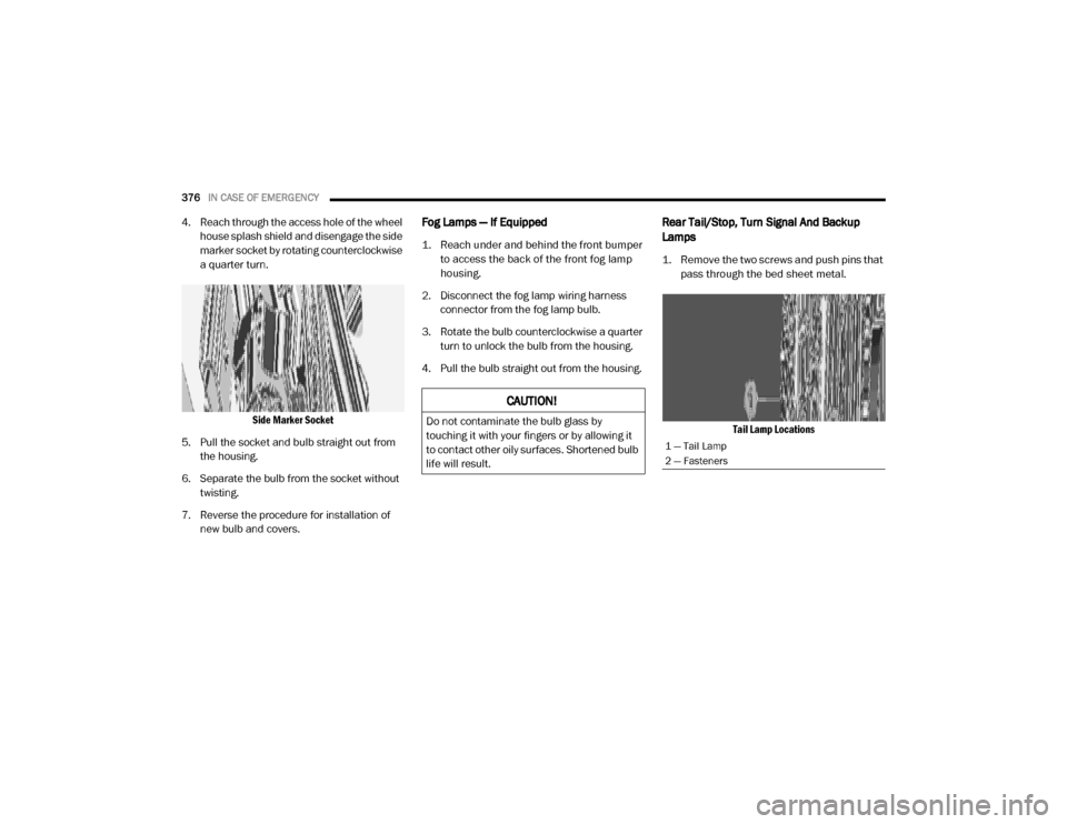
Side Marker Socket
5. Pull the socket and bulb straight out from the housing.
6. Separate the bulb from the socket without twisting.
7. Reverse the procedure for installation of new bulb and covers.Fog Lamps — If Equipped
1. Reach under and behind the front bumper to access the back of the front fog lamp
housing.
2. Disconnect the fog lamp wiring harness connector from the fog lamp bulb.
3. Rotate the bulb counterclockwise a quarter turn to unlock the bulb from the housing.
4. Pull the bulb straight out from the housing.
Rear Tail/Stop, Turn Signal And Backup
Lamps
1. Remove the two screws and push pins that pass through the bed sheet metal.
Tail Lamp Locations
CAUTION!
Do not contaminate the bulb glass by
touching it with your fingers or by allowing it
to contact other oily surfaces. Shortened bulb
life will result.
1 — Tail Lamp
2 — Fasteners
20_DJD2_OM_EN_USC_t.book Page 376
Page 546 of 553
544
J
Jack Location
................................................. 342
Jump Starting................................................ 362
K
Key Fob Panic Alarm
................................................. 15
Programming Additional Key Fobs....... 17, 24
Key Fob Battery Service (Remote Keyless
Entry)
............................................................... 15Key Fob Programming (Remote Keyless
Entry)
............................................................... 17
Keyless Enter-N-Go........................28, 211, 216
Lock The Vehicle’s Doors....... 466, 483, 502
Passive Entry............................................... 28
Passive Entry Programming............. 483, 502
Keys................................................................. 14
Replacement............................................... 24
L
Lane Change And Turn Signals
........................ 52
Lane Change Assist......................................... 52
LaneSense.................................................... 299
Latches.......................................................... 210
Hood........................................................... 74
Lead Free Gasoline........................................ 446
Leaks, Fluid................................................... 210
Life Of Tires................................................... 431
Light Bulbs........................................... 210, 372
Lights............................................................ 210
Air Bag.................................... 130, 181, 209
Automatic High Beam.................................. 50
Brake Assist Warning............................... 148
Brake Warning.......................................... 130
Bulb Replacement.................................... 372
Cab Top Clearance................................... 378Cargo........................................................... 52
Center Mounted Stop............................... 377
Courtesy/Reading....................................... 54Cruise....................................................... 141
Daytime Running......................................... 49
Electronic Stability Program(ESP) Indicator
............................................... 131
Exterior...............................................49, 210Fog........................................................... 376
Four Wheel Drive Indicator....................... 250
Hazard Warning Flasher........................... 338
Headlights............................................ 49, 51High Beam................................................... 50
Hill Descent Control Indicator................... 149
Illuminated Entry......................................... 55
Interior.................................................. 53, 54
Lights On Reminder..................................... 52
Low Fuel................................................... 135
Malfunction Indicator (Check Engine)....... 133
Park.......................................................... 140
Passing........................................................ 51
Seat Belt Reminder.................................. 130
Security Alarm.......................................... 131
Service...................................................... 372
Side Marker.............................................. 379
Traction Control........................................ 148
Transfer Case........................................... 250
Turn Signals............52, 140, 210, 374, 376
Warning Instrument Cluster Descriptions
................................ 131, 140Limited-Slip Differential....................... 264, 418
Load Shed Battery Saver Mode..................... 128
Load Shed Battery Saver On......................... 128Load Shed Electrical Load Reduction........... 128
Load Shed Intelligent Battery Sensor............ 128
Loading Vehicle............................................. 317
Tires.......................................................... 426
LocksAutomatic Door............................................31
Child Protection...........................................31
Power Door..................................................27
Low Tire Pressure System............................. 163Lubrication, Body.......................................... 408
Lug Nuts/Bolts.............................................. 444
M
Maintenance
....................................................74Maintenance Free Battery............................ 395
Maintenance Plan......................................... 386
Maintenance Schedule............... 380, 384, 386
Malfunction Indicator Light (Check
Engine)
................................................. 133, 142
20_DJD2_OM_EN_USC_t.book Page 544