warning lights Ram 2500 2020 Owner's Manual
[x] Cancel search | Manufacturer: RAM, Model Year: 2020, Model line: 2500, Model: Ram 2500 2020Pages: 553, PDF Size: 21.99 MB
Page 5 of 553

3
Power Mirrors — If Equipped ...................... 45
Power Convex Mirror Switch —
If Equipped ................................................... 46 Trailer Towing Mirrors — If Equipped ......... 46
Heated Mirrors — If Equipped ..................... 47
Tilt Side Mirrors In Reverse —
If Equipped ................................................... 47 Power Folding Outside Mirrors For
Standard And Trailer Tow — If Equipped .... 47 Illuminated Vanity Mirror — If Equipped ..... 48
EXTERIOR LIGHTS.................................................49
Multifunction Lever ...................................... 49
Headlight Switch .......................................... 49
Daytime Running Lights (DRLs) —
If Equipped ................................................... 49 High/Low Beam Switch ............................... 50
Automatic High Beam Headlamp Control —
If Equipped ................................................... 50 Flash-To-Pass ............................................... 51
Automatic Headlights — If Equipped ......... 51
Directional LED Headlamp System — If
Equipped ...................................................... 51 Parking Lights And Panel Lights ................. 51
Headlights On With Wipers (Available With
Automatic Headlights Only) ......................... 51 Headlight Delay ............................................ 51
Lights-On Reminder ..................................... 52 Front Fog Lights — If Equipped .................. 52
Turn Signals ................................................ 52
Lane Change Assist — If Equipped ............. 52
Cargo Lights/Trailer Spotter Lights With
Bed Lights — If Equipped............................. 52 Battery Saver ............................................... 53
INTERIOR LIGHTS ................................................ 53
Courtesy Lights ............................................ 53
Illuminated Entry ......................................... 55
WINDSHIELD WIPERS AND WASHERS............. 55
Windshield Wipers ....................................... 55
Rain Sensing Wipers — If Equipped ........... 56
CLIMATE CONTROLS ........................................... 57
Manual Climate Control Overview .............. 57
Automatic Climate Control Overview .......... 61
Climate Control Functions........................... 68
Automatic Temperature Control (ATC) ....... 68
Operating Tips ............................................. 69
WINDOWS ............................................................ 70
Power Windows ........................................... 70
Wind Buffeting ............................................ 72
POWER SUNROOF — IF EQUIPPED .................... 72
Single Pane Power Sunroof —
If Equipped ................................................... 72
HOOD .................................................................... 74
To Open The Hood ...................................... 74
To Close The Hood ....................................... 75 TAILGATE ...............................................................75
Opening ........................................................ 75
Closing.......................................................... 75
Bed Step — If Equipped ............................... 75
GARAGE DOOR OPENER — IF EQUIPPED ..........76
Before You Begin Programming
HomeLink® .................................................. 77 Canadian/Gate Operator Programming..... 79
Using HomeLink®........................................ 80
Security ........................................................ 80
Troubleshooting Tips ................................... 80
General Information .................................... 81
INTERNAL EQUIPMENT ........................................82
Storage ......................................................... 82
Cupholders .................................................. 87
Electrical Power Outlets .............................. 88
Power Inverter — If Equipped ..................... 90
Wireless Charging Pad — If Equipped ....... 91
Overhead Sunglass Storage ....................... 92
PICKUP BOX .........................................................92
Cargo Camera — If Equipped ...................... 93
RAMBOX — IF EQUIPPED .....................................94
RamBox Integrated Box Side Storage
Bins............................................................... 95 RamBox Safety Warning ............................. 96
Bed Divider — If Equipped ........................... 96
Bed Rail Tie-Down System —
If Equipped .................................................. 98
20_DJD2_OM_EN_USC_t.book Page 3
Page 6 of 553

4
SLIDE-IN CAMPERS .......................................... 100 Camper Applications .................................100
EASY-OFF TAILGATE ......................................... 100
Disconnecting The Rear Camera And
Remote Keyless Entry ...............................100 Removing The Tailgate .............................. 101
Locking Tailgate .........................................101
TRI-FOLD TONNEAU COVER — IF EQUIPPED .. 101
Tri-Fold Tonneau Cover Removal ..............102
Tri-Fold Tonneau Cover Installation ..........104
Tri-Fold Tonneau Cover Cleaning ..............107
GETTING TO KNOW YOUR INSTRUMENT PANEL
BASE / MIDLINE INSTRUMENT CLUSTER —
GAS ENGINE ....................................................... 108
Base / Midline Instrument Cluster
Descriptions — Gas Engine .......................109
PREMIUM INSTRUMENT CLUSTER —
GAS ENGINE ....................................................... 111
Premium Instrument Cluster Descriptions —
Gas Engine .................................................112
BASE INSTRUMENT CLUSTER — DIESEL
ENGINE ............................................................... 113
Base Instrument Cluster Descriptions —
Diesel Engine .............................................114
PREMIUM INSTRUMENT CLUSTER — DIESEL
ENGINE ................................................................ 116
Premium Instrument Cluster Descriptions —
Diesel Engine .............................................117 INSTRUMENT CLUSTER DISPLAY ................... 117
Instrument Cluster Display Controls......... 118
Oil Life Reset ............................................. 119
Display Menu Items ................................... 119
Diesel Messages And Warnings — 6.7L
Cummins Diesel Engine ............................ 124 Battery Saver On/Battery Saver Mode
Message — Electrical Load Reduction
Actions — If Equipped ................................ 128
WARNING LIGHTS AND MESSAGES ................130
Red Warning Lights ................................... 130
Yellow Warning Lights ............................... 133
Yellow Indicator Lights .............................. 137
Green Indicator Lights ............................... 140
White Indicator Lights ............................... 141
Blue Indicator Lights.................................. 141
ONBOARD DIAGNOSTIC SYSTEM — OBD II..... 141
Onboard Diagnostic System (OBD II)
Cybersecurity ............................................. 142
EMISSIONS INSPECTION AND MAINTENANCE
PROGRAMS......................................................... 142
SAFETY
SAFETY FEATURES .............................................144
Anti-Lock Brake System (ABS) ................. 144
Electronic Brake Control (EBC) System .... 145 AUXILIARY DRIVING SYSTEMS ........................ 153
Blind Spot Monitoring (BSM) —
If Equipped ................................................ 153 Forward Collision Warning (FCW) With
Mitigation — If Equipped ........................... 160 Tire Pressure Monitoring System
(TPMS) ........................................................ 163
OCCUPANT RESTRAINT SYSTEMS ................. 171
Occupant Restraint Systems Features ... 171
Important Safety Precautions ................... 171
Seat Belt Systems .................................... 172
Supplemental Restraint Systems (SRS)... 181
Child Restraints ......................................... 190
Transporting Pets ...................................... 208
SAFETY TIPS ....................................................... 208
Transporting Passengers .......................... 208
Exhaust Gas .............................................. 208
Safety Checks You Should Make Inside
The Vehicle ................................................ 209 Periodic Safety Checks You Should Make
Outside The Vehicle ................................... 210
20_DJD2_OM_EN_USC_t.book Page 4
Page 14 of 553
12INTRODUCTION
HOW TO USE THIS MANUAL
Essential Information
Consult the Table of Contents to determine
which section contains the information you
desire.
Since the specification of your vehicle depends
on the items of equipment ordered, certain
descriptions and illustrations may differ from
your vehicle's equipment.
The detailed Index at the back of this Owner's
Manual contains a complete listing of all
subjects.
Symbols
Some vehicle components have colored labels
whose symbols indicate precautions to be
observed when using this component. Refer to
“Warning Lights and Messages” in “Getting To
Know Your Instrument Panel” for further infor -
mation on the symbols used in your vehicle.
WARNINGS AND CAUTIONS
This Owner’s Manual contains WARNINGS
against operating procedures that could result
in a collision, bodily injury and/or death. It also
contains CAUTIONS against procedures that
could result in damage to your vehicle. If you do
not read this entire Owner’s Manual, you may
miss important information. Observe all Warn -
ings and Cautions.
VAN CONVERSIONS/CAMPERS
The New Vehicle Limited Warranty does not
apply to body modifications or special equip -
ment installed by van conversion/camper
manufacturers/body builders. US residents
refer to the Warranty Information, Section
2.1.C. Canadian residents refer to the “What Is
Not Covered” section of the Warranty Informa -
tion. Such equipment includes video monitors,
VCRs, heaters, stoves, refrigerators, etc. For
warranty coverage and service on these items,
contact the applicable manufacturer.
Operating instructions for the special equip -
ment installed by the conversion/camper
manufacturer should also be supplied with your
vehicle. If these instructions are missing, please
contact an authorized dealer for assistance in obtaining replacement documents from the
applicable manufacturer.
For information on the Body Builder’s Guide
refer to
www.ramtrucks.com . This website
contains dimensional and technical specifica -
tions for your vehicle. It is intended for Second
Stage Manufacturer's technical support. For
service issues, contact an authorized dealer.
VEHICLE MODIFICATIONS/ALTERATIONS
WARNING!
Any modifications or alterations to this vehicle
could seriously affect its roadworthiness and
safety and may lead to a collision resulting in
serious injury or death.
20_DJD2_OM_EN_USC_t.book Page 12
Page 22 of 553
20GETTING TO KNOW YOUR VEHICLE
REMOTE START — IF EQUIPPED
(GASOLINE)
This system uses the key fob to start
the engine conveniently from outside
the vehicle while still maintaining
security. The system has a range of
approximately 300 ft (91 m).
NOTE:
Obstructions between the vehicle and the key
fob may reduce this range.
How To Use Remote Start
All of the following conditions must be met
before the engine will remote start:
Gear selector in PARK
Doors closed
Hood closed
Hazard switch off
Brake switch inactive (brake pedal not
pushed)
Battery at an acceptable charge level
PANIC button not pushed
Fuel meets minimum requirement
System not disabled from previous remote
start event
Vehicle security alarm not active
Malfunction Indicator Light is not illuminated
Remote Start Abort Message
The following messages will display in the
instrument cluster display if the vehicle fails to
remote start or exits remote start prematurely:
Remote Start Cancelled — Door Open
Remote Start Cancelled — Hood Open
Remote Start Cancelled — Fuel Low
Remote Start Cancelled — System Fault
Remote Start Disabled — Start Vehicle to
Reset
The instrument cluster display message stays
active until the ignition is placed in the ON/RUN
position.
To Enter Remote Start Mode
Push and release the Remote Start
button on the key fob twice within five
seconds. The parking lights will flash,
vehicle doors will lock, and the horn
will chirp twice (if programmed). Once the
vehicle has started, the engine will run for
15 minutes.
WARNING!
Do not start or run an engine in a closed
garage or confined area. Exhaust gas
contains Carbon Monoxide (CO) which is
odorless and colorless. Carbon Monoxide is
poisonous and can cause serious injury or
death when inhaled.
Keep key fobs away from children. Opera -
tion of the Remote Start System, windows,
door locks or other controls could cause
serious injury or death.
20_DJD2_OM_EN_USC_t.book Page 20
Page 24 of 553
22GETTING TO KNOW YOUR VEHICLE
Le présent appareil est conforme aux CNR
d`Innovation, Science and Economic Develop -
ment applicables aux appareils radio exempts
de licence. L'exploitation est autorisée aux deux
conditions suivantes:
1. l'appareil ne doit pas produire de brouil -
lage, et
2. l'utilisateur de l'appareil doit accepter tout brouillage radioélectrique subi, même si le
brouillage est susceptible d'en comprom -
ettre le fonctionnement.
La operación de este equipo está sujeta a las
siguientes dos condiciones:
1. es posible que este equipo o dispositivo no cause interferencia perjudicial y
2. este equipo o dispositivo debe aceptar cual -
quier interferencia, incluyendo la que
pueda causar su operación no deseada.
NOTE:
Changes or modifications not expressly
approved by the party responsible for compli -
ance could void the user’s authority to operate
the equipment.REMOTE START— IF EQUIPPED (DIESEL)
This system uses the key fob to start
the engine conveniently from outside
the vehicle while still maintaining
security. The system has a range of
approximately 300 ft (91 m).
NOTE:
Obstructions between the vehicle and the
key fob may reduce this range.
The Remote Start system will wait for the
“Wait To Start” Indicator Light to extinguish
before cranking the engine. This allows time
for the intake heater to preheat the incoming
air, and is normal operation in cold weather.
Refer to “Wait To Start Light,” located in
“Warning Lights And Messages” in “Getting
To Know Your Instrument Panel” for more
information.
How To Use Remote Start
All of the following conditions must be met
before the engine will remote start:
Transmission in PARK
Doors closed
Hood closed
Hazard switch off
Brake switch inactive (brake pedal not
pushed)
Battery at an acceptable charge level
PANIC button not pushed
Fuel meets minimum requirement
Water In Fuel Indicator Light is not illumi -
nated
Wait To Start Light Indicator Light is not illu -
minated
Malfunction Indicator Light is not illuminated
20_DJD2_OM_EN_USC_t.book Page 22
Page 25 of 553
GETTING TO KNOW YOUR VEHICLE23
Remote Start Abort Message
The following messages will display in the
instrument cluster display if the vehicle fails to
remote start or exits remote start prematurely:
Remote Start Aborted — Door Open
Remote Start Aborted — Hood Open
Remote Start Aborted — Fuel Low
Remote Start Aborted — System Fault
The instrument cluster display message is
stored until the ignition is placed in the ON/RUN
position.
To Enter Remote Start Mode
Push and release the Remote Start button on
the key fob twice, within five seconds. The
parking lights will flash and the horn will chirp
twice (if programmed). In cold ambient
temperature conditions, the diesel vehicle may
delay crank up to 30 seconds for the Intake Air
Heater. Once the vehicle has started, the
engine will run for 15 minutes.
NOTE:
Crank may be delayed up to 75 seconds for
intake air heater operation at high altitudes,
and/or extreme cold.
The park lamps will turn on and remain on
during Remote Start mode.
For security, power window and power
sunroof operation (if equipped) are disabled
when the vehicle is in the Remote Start
mode.
Additional features, such as windshield
wipers, will also not be available while the
vehicle is in the Remote Start mode.
The engine can be started two consecutive
times (two 15 minute cycles) with the key
fob. However, the ignition switch must be placed in the ON/RUN position before you
can repeat the start sequence for a third
cycle.
To Exit Remote Start Mode Without Driving
The Vehicle
Push and release the Remote Start button one
time or allow the engine to run for the entire
15 minute cycle.
NOTE:
To avoid unintentional shut downs, the system
will disable for two seconds after receiving a
valid Remote Start request.
To Exit Remote Start Mode And Drive The
Vehicle
To exit Remote Start Mode and drive the vehicle
before the end of the 15 minute cycle, push and
release the unlock button on the key fob to
unlock the door and disarm the vehicle security
alarm System (if equipped). Then, prior to the
end of the 15 minute cycle, place the ignition in
the ON/RUN position.
NOTE:
The ignition switch must be in the ON/RUN posi
-
tion in order to drive the vehicle.
WARNING!
Do not start or run an engine in a closed
garage or confined area. Exhaust gas
contains Carbon Monoxide (CO) which is
odorless and colorless. Carbon Monoxide is
poisonous and can cause serious injury or
death when inhaled.
Keep key fobs away from children. Opera -
tion of the Remote Start System, windows,
door locks or other controls could cause
serious injury or death.
2
20_DJD2_OM_EN_USC_t.book Page 23
Page 91 of 553
GETTING TO KNOW YOUR VEHICLE89
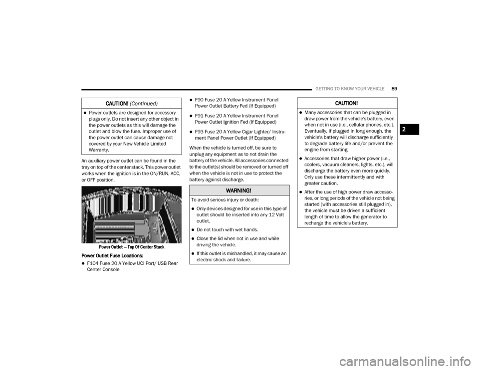
An auxiliary power outlet can be found in the
tray on top of the center stack. This power outlet
works when the ignition is in the ON/RUN, ACC,
or OFF position.
Power Outlet — Top Of Center Stack
Power Outlet Fuse Locations:
F104 Fuse 20 A Yellow UCI Port/ USB Rear
Center Console
F90 Fuse 20 A Yellow Instrument Panel
Power Outlet Battery Fed (If Equipped)
F91 Fuse 20 A Yellow Instrument Panel
Power Outlet Ignition Fed (If Equipped)
F93 Fuse 20 A Yellow Cigar Lighter/ Instru -
ment Panel Power Outlet (If Equipped)
When the vehicle is turned off, be sure to
unplug any equipment as to not drain the
battery of the vehicle. All accessories connected
to the outlet(s) should be removed or turned off
when the vehicle is not in use to protect the
battery against discharge.
Power outlets are designed for accessory
plugs only. Do not insert any other object in
the power outlets as this will damage the
outlet and blow the fuse. Improper use of
the power outlet can cause damage not
covered by your New Vehicle Limited
Warranty.
CAUTION! (Continued)
WARNING!
To avoid serious injury or death:
Only devices designed for use in this type of
outlet should be inserted into any 12 Volt
outlet.
Do not touch with wet hands.
Close the lid when not in use and while
driving the vehicle.
If this outlet is mishandled, it may cause an
electric shock and failure.
CAUTION!
Many accessories that can be plugged in
draw power from the vehicle's battery, even
when not in use (i.e., cellular phones, etc.).
Eventually, if plugged in long enough, the
vehicle's battery will discharge sufficiently
to degrade battery life and/or prevent the
engine from starting.
Accessories that draw higher power (i.e.,
coolers, vacuum cleaners, lights, etc.), will
discharge the battery even more quickly.
Only use these intermittently and with
greater caution.
After the use of high power draw accesso -
ries, or long periods of the vehicle not being
started (with accessories still plugged in),
the vehicle must be driven a sufficient
length of time to allow the generator to
recharge the vehicle's battery.
2
20_DJD2_OM_EN_USC_t.book Page 89
Page 131 of 553
GETTING TO KNOW YOUR INSTRUMENT PANEL129
NOTE:
The charging system is independent from
load reduction. The charging system
performs a diagnostic on the charging
system continuously.
If the Battery Charge Warning Light is on it
may indicate a problem with the charging
system. Refer to “Warning Lights And
Messages” in “Getting To Know Your Instru-
ment Panel” for further information.
The electrical loads that may be switched off (if
equipped), and vehicle functions which can be
affected by load reduction:
Heated Seats/Vented Seats/Heated Wheel
Rear Defroster And Heated Mirrors
HVAC System
115 Volts AC Power Inverter System
Audio and Telematics System Loss of the battery charge may indicate one or
more of the following conditions:
The charging system cannot deliver enough
electrical power to the vehicle system
because the electrical loads are larger than
the capability of charging system. The
charging system is still functioning properly.
Turning on all possible vehicle electrical
loads (e.g. HVAC to max settings, exterior and
interior lights, overloaded power outlets
+12 Volts, 115 Volts AC, USB ports) during
certain driving conditions (city driving,
towing, frequent stopping).
Installing options like additional lights,
upfitter electrical accessories, audio
systems, alarms and similar devices.
Unusual driving cycles (short trips separated
by long parking periods).
The vehicle was parked for an extended
period of time (weeks, months).
The battery was recently replaced and was
not charged completely.
The battery was discharged by an electrical
load left on when the vehicle was parked.
The battery was used for an extended period
with the engine not running to supply radio,
lights, chargers, +12 Volts portable appli
-
ances like vacuum cleaners, game consoles
and similar devices.
What to do when an electrical load reduction
action message is present (“Battery Saver On”
or “Battery Saver Mode”)
During a trip:
Reduce power to unnecessary loads if
possible:
Turn off redundant lights (interior or exte -
rior).
Check what may be plugged in to power outlets +12 Volts, 115 Volts AC, USB
ports.
Check HVAC settings (blower, tempera -
ture).
Check the audio settings (volume).
3
20_DJD2_OM_EN_USC_t.book Page 129
Page 132 of 553
130GETTING TO KNOW YOUR INSTRUMENT PANEL
After a trip:
Check if any aftermarket equipment was
installed (additional lights, upfitter electrical
accessories, audio systems, alarms) and
review specifications if any (load and Ignition
Off Draw currents).
Evaluate the latest driving cycles (distance,
driving time and parking time).
The vehicle should have service performed if
the message is still present during consecu-
tive trips and the evaluation of the vehicle
and driving pattern did not help to identify the
cause.
WARNING LIGHTS AND MESSAGES
The warning/indicator lights will illuminate in
the instrument panel together with a dedicated
message and/or acoustic signal when appli -
cable. These indications are indicative and
precautionary and as such must not be consid -
ered as exhaustive. Always refer to the informa-
tion in this chapter in the event of a failure
indication. All active telltales will display first if
applicable. The system check menu may
appear different based upon equipment
options and current vehicle status. Some tell -
tales are optional and may not appear.
Red Warning Lights
Seat Belt Reminder Warning Light
This warning light indicates when the
driver or passenger seat belt is
unbuckled. When the ignition is first
placed in the ON/RUN or ACC/ON/
RUN position and if the driver’s seat belt is
unbuckled, a chime will sound and the light will
turn on. When driving, if the driver or front
passenger seat belt remains unbuckled, the
Seat Belt Reminder Light will flash or remain on
continuously and a chime will sound.
Refer to “Occupant Restraint Systems” in
“Safety” for further information.
Air Bag Warning Light
This warning light will illuminate to
indicate a fault with the air bag, and
will turn on for four to eight seconds
as a bulb check when the ignition is
placed in the ON/RUN or ACC/ON/RUN posi -
tion. This light will illuminate with a single chime
when a fault with the air bag has been detected,
it will stay on until the fault is cleared. If the light
is either not on during startup, stays on, or turns
on while driving, have the system inspected at
an authorized dealer as soon as possible.
Brake Warning Light
This warning light monitors various
brake functions, including brake fluid
level and parking brake application. If
the brake light turns on it may indi -
cate that the parking brake is applied, that the
brake fluid level is low, or that there is a
problem with the anti-lock brake system reser -
voir.
If the light remains on when the parking brake
has been disengaged, and the fluid level is at
the full mark on the master cylinder reservoir, it
indicates a possible brake hydraulic system
malfunction or that a problem with the Brake
Booster has been detected by the Anti-Lock
Brake System (ABS) / Electronic Stability
Control (ESC) system. In this case, the light will
remain on until the condition has been
corrected. If the problem is related to the brake
booster, the ABS pump will run when applying
the brake, and a brake pedal pulsation may be
felt during each stop.
The dual brake system provides a reserve
braking capacity in the event of a failure to a
portion of the hydraulic system. A leak in either
half of the dual brake system is indicated by the
Brake Warning Light, which will turn on when
20_DJD2_OM_EN_USC_t.book Page 130
Page 135 of 553
GETTING TO KNOW YOUR INSTRUMENT PANEL133
Door Open Warning Light
This indicator will illuminate when a
door is ajar/open and not fully closed.
NOTE:
If the vehicle is moving there will also be a single
chime.
Yellow Warning Lights
Adaptive Cruise Control (ACC) Fault Warning
Light — If Equipped
This warning light will illuminate to
indicate a fault in the ACC system.
Contact a local authorized dealer for
service.
For further information, refer to “Adaptive
Cruise Control (ACC)” in “Starting And Oper -
ating.”
Air Suspension Fault Warning Light — If
Equipped
This light will illuminate when a fault
is detected with the air suspension
system.
Refer to “Air Suspension System — If Equipped”
in “Starting And Operating” for further informa -
tion.
Engine Check/Malfunction Indicator Warning
Light (MIL)
The Engine Check/Malfunction Indi -
cator Light (MIL) is a part of an
Onboard Diagnostic System called
OBD II that monitors engine and auto -
matic transmission control systems. This warning light will illuminate when the ignition is
in the ON/RUN position before engine start. If
the bulb does not come on when turning the
ignition switch from OFF to ON/RUN, have the
condition checked promptly.
Certain conditions, such as a loose or missing
gas cap, poor quality fuel, etc., may illuminate
the light after engine start. The vehicle should
be serviced if the light stays on through several
typical driving styles. In most situations, the
vehicle will drive normally and will not require
towing.
When the engine is running, the MIL may flash
to alert serious conditions that could lead to
immediate loss of power or severe catalytic
converter damage. The vehicle should be
serviced by an authorized dealer as soon as
possible if this occurs.
WARNING!
If you continue operating the vehicle when
the Transmission Temperature Warning Light
is illuminated you could cause the fluid to boil
over, come in contact with hot engine or
exhaust components and cause a fire.
CAUTION!
Continuous driving with the Transmission
Temperature Warning Light illuminated will
eventually cause severe transmission
damage or transmission failure.
3
20_DJD2_OM_EN_USC_t.book Page 133