ignition Ram 3500 2017 Workshop Manual
[x] Cancel search | Manufacturer: RAM, Model Year: 2017, Model line: 3500, Model: Ram 3500 2017Pages: 734, PDF Size: 7.3 MB
Page 184 of 734
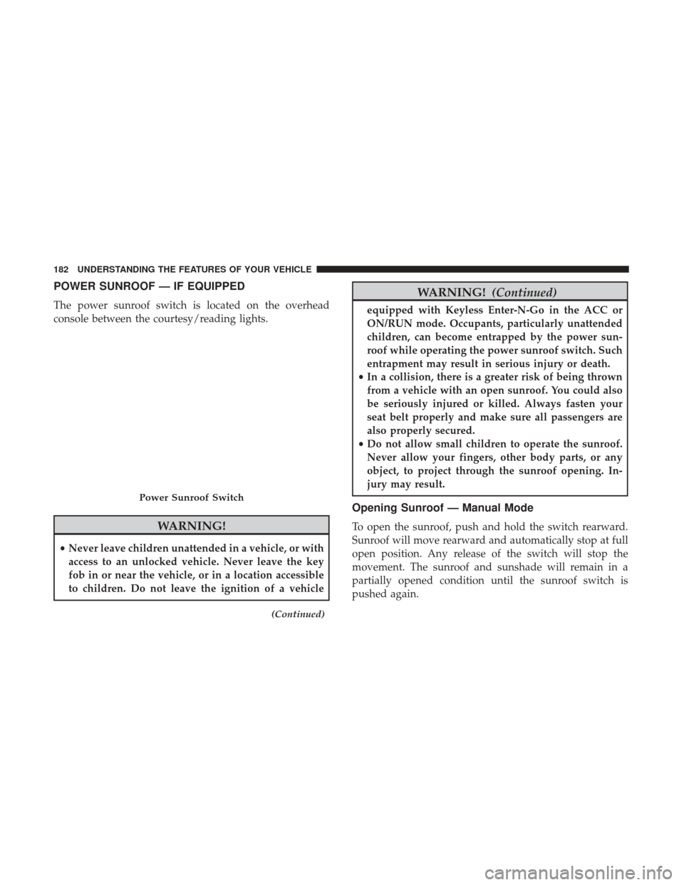
POWER SUNROOF — IF EQUIPPED
The power sunroof switch is located on the overhead
console between the courtesy/reading lights.
WARNING!
•Never leave children unattended in a vehicle, or with
access to an unlocked vehicle. Never leave the key
fob in or near the vehicle, or in a location accessible
to children. Do not leave the ignition of a vehicle
(Continued)
WARNING! (Continued)
equipped with Keyless Enter-N-Go in the ACC or
ON/RUN mode. Occupants, particularly unattended
children, can become entrapped by the power sun-
roof while operating the power sunroof switch. Such
entrapment may result in serious injury or death.
• In a collision, there is a greater risk of being thrown
from a vehicle with an open sunroof. You could also
be seriously injured or killed. Always fasten your
seat belt properly and make sure all passengers are
also properly secured.
• Do not allow small children to operate the sunroof.
Never allow your fingers, other body parts, or any
object, to project through the sunroof opening. In-
jury may result.
Opening Sunroof — Manual Mode
To open the sunroof, push and hold the switch rearward.
Sunroof will move rearward and automatically stop at full
open position. Any release of the switch will stop the
movement. The sunroof and sunshade will remain in a
partially opened condition until the sunroof switch is
pushed again.
Power Sunroof Switch
182 UNDERSTANDING THE FEATURES OF YOUR VEHICLE
Page 186 of 734
Wind Buffeting
Wind buffeting can be described as the perception of
pressure on the ears or a helicopter-type sound in the ears.
Your vehicle may exhibit wind buffeting with the windows
down, or the sunroof (if equipped) in certain open or
partially open positions. This is a normal occurrence and
can be minimized. If the buffeting occurs with the rear
windows open, open the front and rear windows together
to minimize the buffeting. If the buffeting occurs with the
sunroof open, adjust the sunroof opening to minimize the
buffeting or open any window.
Sunroof Maintenance
Use only a nonabrasive cleaner and a soft cloth to clean the
glass panel.
Ignition Off Operation
The power sunroof switch will remain active in Accessory
Delay for up to approximately ten minutes after the
ignition switch is turned to the lock position. Opening
either front door will cancel this feature.
NOTE:Ignition Off time is programmable through the
Uconnect System. Refer to “Uconnect Settings/Customer
Programmable Features” in “Understanding Your Instru-
ment Panel” for further information.
ELECTRICAL POWER OUTLETS
The auxiliary 12 Volt (13 Amp) power outlets can provide
power for in-cab accessories designed for use with the
standard “cigar lighter” plug. The 12 Volt power outlets
and USB Port (Charge Only) have a cap attached to the
outlet indicating “12V DC,” together with either a key
symbol, battery symbol, or USB symbol.
A key symbol indicates that the key must be in the
ON/RUN or ACC positions for the outlet to provide
power. The battery symbol indicates that the outlet is
connected to the battery, and can provide power at all
times.
NOTE: To ensure proper operation, a MOPAR knob and
element must be used.
CAUTION!
• Do not exceed the maximum power of 160 Watts
(13 Amps) at 12 Volts. If the 160 Watts (13 Amps)
power rating is exceeded, the fuse protecting the
system will need to be replaced.
(Continued)
184 UNDERSTANDING THE FEATURES OF YOUR VEHICLE
Page 192 of 734

To turn on the power outlet, simply plug in the device. The
outlet automatically turns off when the device is un-
plugged.
NOTE:Due to built-in overload protection, the power
inverter will shut down if the power rating is exceeded.
WARNING!
To avoid serious injury or death:
• Do not insert any objects into the receptacles.
• Do not touch with wet hands.
• Close the lid when not in use.
• If this outlet is mishandled, it may cause an electric
shock and failure.
AUXILIARY SWITCHES — IF EQUIPPED
There can be up to five auxiliary switches located in the
lower switch bank of the instrument panel which can be
used to power various electronic devices and PTO (Power
Take Off) – If Equipped. If Power Take Off is equipped, it
will take the place of the fifth Auxiliary switch. Connec-
tions to the switches are found under the hood in the
connectors attached to the auxiliary Power Distribution
Center.
You have the ability to configure the functionality of the
auxiliary switches via the instrument cluster display. All
switches can now be configured for setting the switch type
operation to latching or momentary, power source of either
battery or ignition, and ability to hold last state across key
cycles.
NOTE: Holding last state conditions are met when switch
type is set to latching and power source is set to ignition.
For further information on using the auxiliary switches,
please refer to the Ram Body Builders Guide by accessing
www.rambodybuilder.com and choosing the appropriate
links.
190 UNDERSTANDING THE FEATURES OF YOUR VEHICLE
Page 237 of 734
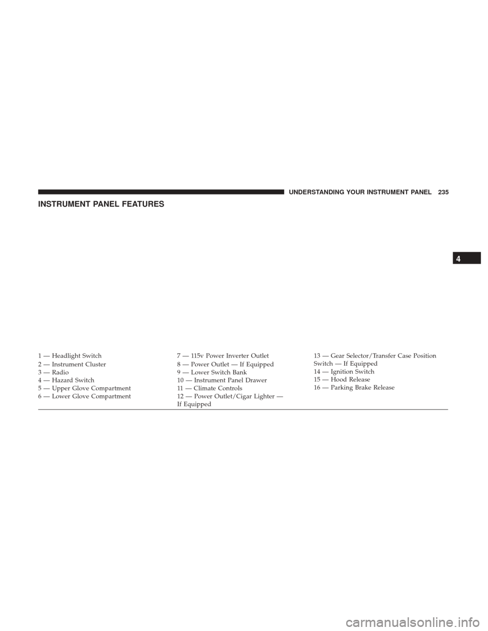
INSTRUMENT PANEL FEATURES
1 — Headlight Switch7 — 115v Power Inverter Outlet13 — Gear Selector/Transfer Case Position
Switch — If Equipped
2 — Instrument Cluster 8 — Power Outlet — If Equipped
14 — Ignition Switch
3 — Radio 9 — Lower Switch Bank
15 — Hood Release
4 — Hazard Switch 10 — Instrument Panel Drawer
16 — Parking Brake Release
5 — Upper Glove Compartment 11 — Climate Controls
6 — Lower Glove Compartment 12 — Power Outlet/Cigar Lighter —
If Equipped
4
UNDERSTANDING YOUR INSTRUMENT PANEL 235
Page 239 of 734
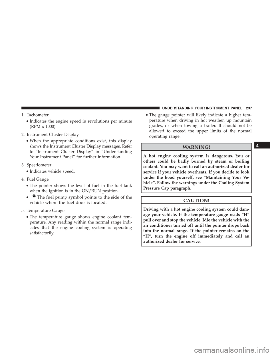
1. Tachometer•Indicates the engine speed in revolutions per minute
(RPM x 1000).
2. Instrument Cluster Display •When the appropriate conditions exist, this display
shows the Instrument Cluster Display messages. Refer
to “Instrument Cluster Display” in “Understanding
Your Instrument Panel” for further information.
3. Speedometer •Indicates vehicle speed.
4. Fuel Gauge •The pointer shows the level of fuel in the fuel tank
when the ignition is in the ON/RUN position.
•
The fuel pump symbol points to the side of the
vehicle where the fuel door is located.
5. Temperature Gauge
•The temperature gauge shows engine coolant tem-
perature. Any reading within the normal range indi-
cates that the engine cooling system is operating
satisfactorily. •
The gauge pointer will likely indicate a higher tem-
perature when driving in hot weather, up mountain
grades, or when towing a trailer. It should not be
allowed to exceed the upper limits of the normal
operating range.
WARNING!
A hot engine cooling system is dangerous. You or
others could be badly burned by steam or boiling
coolant. You may want to call an authorized dealer for
service if your vehicle overheats. If you decide to look
under the hood yourself, see “Maintaining Your Ve-
hicle”. Follow the warnings under the Cooling System
Pressure Cap paragraph.
CAUTION!
Driving with a hot engine cooling system could dam-
age your vehicle. If the temperature gauge reads “H”
pull over and stop the vehicle. Idle the vehicle with the
air conditioner turned off until the pointer drops back
into the normal range. If the pointer remains on the
“H”, turn the engine off immediately and call an
authorized dealer for service.
4
UNDERSTANDING YOUR INSTRUMENT PANEL 237
Page 241 of 734
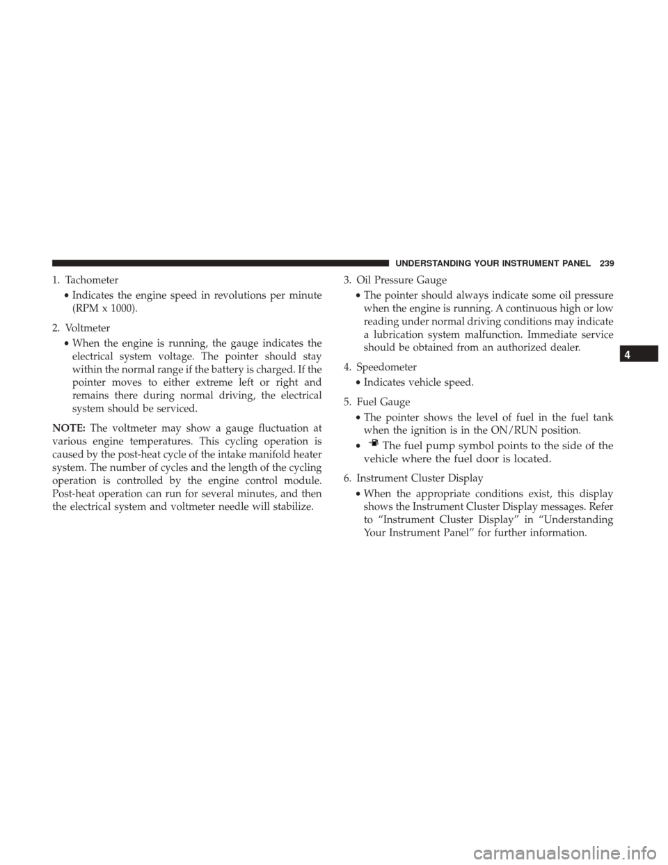
1. Tachometer•Indicates the engine speed in revolutions per minute
(RPM x 1000).
2. Voltmeter •When the engine is running, the gauge indicates the
electrical system voltage. The pointer should stay
within the normal range if the battery is charged. If the
pointer moves to either extreme left or right and
remains there during normal driving, the electrical
system should be serviced.
NOTE: The voltmeter may show a gauge fluctuation at
various engine temperatures. This cycling operation is
caused by the post-heat cycle of the intake manifold heater
system. The number of cycles and the length of the cycling
operation is controlled by the engine control module.
Post-heat operation can run for several minutes, and then
the electrical system and voltmeter needle will stabilize. 3. Oil Pressure Gauge
•The pointer should always indicate some oil pressure
when the engine is running. A continuous high or low
reading under normal driving conditions may indicate
a lubrication system malfunction. Immediate service
should be obtained from an authorized dealer.
4. Speedometer •Indicates vehicle speed.
5. Fuel Gauge •The pointer shows the level of fuel in the fuel tank
when the ignition is in the ON/RUN position.
•
The fuel pump symbol points to the side of the
vehicle where the fuel door is located.
6. Instrument Cluster Display
•When the appropriate conditions exist, this display
shows the Instrument Cluster Display messages. Refer
to “Instrument Cluster Display” in “Understanding
Your Instrument Panel” for further information.
4
UNDERSTANDING YOUR INSTRUMENT PANEL 239
Page 243 of 734
Red Telltale Indicator Lights
Seat Belt Reminder Warning Light
Red TelltaleLight What It Means
Seat Belt Reminder Warning Light
When the ignition is first placed in the ON/RUN position, if the driver ’s seat belt is unbuckled, a
chime will sound and the light will turn on. When driving, if the driver or front passenger seat
belt remains unbuckled, the Seat Belt Reminder Light will flash or remain on continuously and a
chime will sound. Refer to “Occupant Restraints” in “Things To Know Before Starting Your Ve-
hicle” for further information.
Air Bag Warning Light
Red Telltale
Light What It Means
Air Bag Warning Light
This light will turn on for four to eight seconds as a bulb check when the ignition is placed in the
ON/RUN position. If the light is either not on during startup, stays on, or turns on while driv-
ing, have the system inspected at an authorized dealer as soon as possible. This light will illumi-
nate with a single chime when a fault with the Air Bag Warning Light has been detected, it will
stay on until the fault is cleared. If the light comes on intermittently or remains on while driving,
have an authorized dealer service the vehicle immediately.
4
UNDERSTANDING YOUR INSTRUMENT PANEL 241
Page 245 of 734
The dual brake system provides a reserve braking capacity
in the event of a failure to a portion of the hydraulic
system. A leak in either half of the dual brake system is
indicated by the Brake Warning Light, which will turn on
when the brake fluid level in the master cylinder has
dropped below a specified level.
The light will remain on until the cause is corrected.
NOTE:The light may flash momentarily during sharp
cornering maneuvers, which change fluid level conditions.
The vehicle should have service performed, and the brake
fluid level checked.
If brake failure is indicated, immediate repair is necessary.
WARNING!
Driving a vehicle with the red brake light on is
dangerous. Part of the brake system may have failed. It
will take longer to stop the vehicle. You could have a
collision. Have the vehicle checked immediately. Vehicles equipped with the Anti-Lock Brake System (ABS)
are also equipped with Electronic Brake Force Distribution
(EBD).
CAUTION!
In the event of an EBD failure, the Brake Warning
Light will turn on along with the ABS Light. Immedi-
ate repair to the ABS system is required.
Operation of the Brake Warning Light can be checked by
placing the ignition in the ON/RUN position. The light
should illuminate for approximately two seconds. The light
should then turn off unless the parking brake is applied or
a brake fault is detected. If the light does not illuminate,
have the light inspected by an authorized dealer.
The light also will turn on when the parking brake is
applied with the ignition placed in the ON/RUN position.
NOTE: This light shows only that the parking brake is
applied. It does not show the degree of brake application.4
UNDERSTANDING YOUR INSTRUMENT PANEL 243
Page 248 of 734
Electronic Throttle Control (ETC) Warning Light
Red TelltaleLight What It Means
Electronic Throttle Control (ETC) Warning Light
This light informs you of a problem with the Electronic Throttle Control (ETC) system. If a prob-
lem is detected while the engine is running, the light will either stay on or flash depending on
the nature of the problem. Cycle the ignition key when the vehicle is safely and completely
stopped and the transmission is placed in the PARK position. The light should turn off. If the
light remains on with the engine running, your vehicle will usually be drivable; however, see an
authorized dealer for service as soon as possible.
If the light continues to flash when the engine is running, immediate service is required and you
may experience reduced performance, an elevated/rough idle, or engine stall and your vehicle
may require towing. The light will come on when the ignition is first turned to ON/RUN and
remain on briefly as a bulb check. If the light does not come on during starting, have the system
checked by an authorized dealer.
246 UNDERSTANDING YOUR INSTRUMENT PANEL
Page 251 of 734
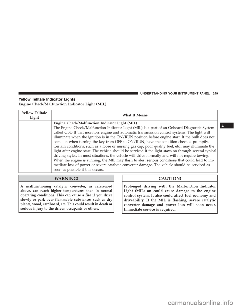
Yellow Telltale Indicator Lights
Engine Check/Malfunction Indicator Light (MIL)
Yellow TelltaleLight What It Means
Engine Check/Malfunction Indicator Light (MIL)
The Engine Check/Malfunction Indicator Light (MIL) is a part of an Onboard Diagnostic System
called OBD II that monitors engine and automatic transmission control systems. The light will
illuminate when the ignition is in the ON/RUN position before engine start. If the bulb does not
come on when turning the key from OFF to ON/RUN, have the condition checked promptly.
Certain conditions, such as a loose or missing gas cap, poor quality fuel, etc., may illuminate the
light after engine start. The vehicle should be serviced if the light stays on through several typical
driving styles. In most situations, the vehicle will drive normally and will not require towing.
When the engine is running, the MIL may flash to alert serious conditions that could lead to im-
mediate loss of power or severe catalytic converter damage. The vehicle should be serviced as
soon as possible if this occurs.
WARNING!
A malfunctioning catalytic converter, as referenced
above, can reach higher temperatures than in normal
operating conditions. This can cause a fire if you drive
slowly or park over flammable substances such as dry
plants, wood, cardboard, etc. This could result in death or
serious injury to the driver, occupants or others.
CAUTION!
Prolonged driving with the Malfunction Indicator
Light (MIL) on could cause damage to the engine
control system. It also could affect fuel economy and
driveability. If the MIL is flashing, severe catalytic
converter damage and power loss will soon occur.
Immediate service is required.
4
UNDERSTANDING YOUR INSTRUMENT PANEL 249