brake light Ram 3500 2018 Owner's Manual
[x] Cancel search | Manufacturer: RAM, Model Year: 2018, Model line: 3500, Model: Ram 3500 2018Pages: 372, PDF Size: 7.1 MB
Page 149 of 372

cally crank when the "Wait To Start" time
has elapsed. See the section "Starting Pro-
cedure Engine Manifold Air Temperature
0°F to 66°F (18° C to 19°C)" in the Diesel
Supplement for more information.
To Turn Off The Engine Using ENGINE START/
STOP Button
1. Place the gear selector in PARK, then push and release the ENGINE START/
STOP button.
2. The ignition will return to the OFF mode.
3. If the gear selector is not in PARK and the ENGINE START/STOP button is pushed
once, the instrument cluster will display a
“Vehicle Not In Park” message and the
engine will remain running. Never leave a
vehicle out of the PARK position, or it
could roll.
4. If the gear selector is in NEUTRAL, and the vehicle speed below 5 mph (8 km/h),
pushing the START/STOP button once will
turn the engine off. The ignition will re-
main in the ACC mode.
5.
If the vehicle speed is above 5 mph (8 km/h),
the ENGINE START/STOP button must be held for two seconds (or three short pushes
in a row) to turn the engine off. The ignition
will remain in the ACC mode (NOT the OFF
mode) if the engine is turned off when the
transmission is not in PARK.
NOTE:
If the ignition is left in the ACC or ON/RUN
(engine not running) mode and the transmis-
sion is in PARK, the system will automatically
time out after 30 minutes of inactivity and
the ignition return to the OFF mode.
ENGINE START/STOP Button Functions — With
Driver’s Foot OFF The Brake Pedal (In PARK Or
NEUTRAL Position)
The ENGINE START/STOP button operates
similar to an ignition switch. It has three
positions, OFF, ACC, RUN. To change the
ignition switch positions without starting the
vehicle and use the accessories follow these
steps:
1. Starting with the ignition in the OFF
position:
2. Push the ENGINE START/STOP button once to change the ignition to the ACC
position. 3. Push the ENGINE START/STOP button a
second time to change the ignition to the
RUN position.
4. Push the ENGINE START/STOP button a third time to return the ignition to the OFF
position.
Keyless Enter-N-Go Starting Procedure —
Engine Manifold Air Temperature 0° F To
66° F (–18° C to 19° C)
NOTE:
The temperature displayed in the instrument
cluster does not necessarily reflect the en-
gine manifold air temperature. Refer to “In-
strument Cluster Display” in “Getting To
Know Your Instrument Panel” for further in-
formation. When engine temperatures fall
below 66°F (19°C) the “Wait To Start Light”
will remain on indicating the intake manifold
heater system is active.
Follow the steps in the “Normal Starting”
procedure except:
1. Pushing the engine start button with thedriver’s foot on the brake will move the
147
Page 150 of 372
ignition from OFF or ACC to RUN, and will
illuminate the "Wait To Start" telltale. The
engine will not immediately crank, this is
normal operation.
2. The “Wait To Start" telltale will remain on for a period of time that varies depending
on the engine temperature.
3. While the "Wait to Start" telltale is on, the instrument cluster will additionally dis-
play a gauge or bar whose initial length
represents the full "Wait to Start" time
period. Its length will decrease until it
disappears when the "Wait to Start" time
has elapsed.
CAUTION!
If the “Water in Fuel Indicator Light” re-
mains on, DO NOT START engine before
you drain the water from the fuel filters to
avoid engine damage. Refer to “Draining
Fuel/Water Separator Filter” in “Dealer
Service” under “Servicing And Mainte-
nance” for further information. 4. After the engine “Wait To Start” telltale
goes off, the engine will automatically
crank.
CAUTION!
Do not crank engine for more than 15 sec-
onds at a time or starter motor damage
may result. Turn the ignition switch to the
OFF position and wait at least two minutes
for the starter to cool before repeating start
procedure.
5. After engine start-up, check to see that there is oil pressure.
6. Allow the engine to idle about three min- utes until the manifold heaters have com-
pleted the post-heat cycle.
7. Release the parking brake and drive.
NOTE:
• Engine idle speed will automatically in- crease to 1,000 RPM and engage the Vari-
able Geometry Turbocharger at low coolant
temperatures to improve engine warm-up. • The engine may not automatically crank
after the engine "Wait To Start" telltale goes
off if a door or the hood is ajar.
• If the engine stalls, or if the ignition switch is left ON for more than two minutes after
the “Wait To Start Light” goes out, reset the
grid heaters by turning the ignition switch
to the OFF position for at least five seconds
and then back ON. Repeat steps 1 through
7 of “Keyless Enter-N-Go Starting Proce-
dure – Engine Manifold Air Temperature
Below 66° F (19° C).”
Extreme Cold Weather
The Cummins diesel engine is equipped with
several features designed to assist cold
weather starting and operation:
• The engine block heater is a resistance
heater installed in the water jacket of the
engine just above and behind the oil filter.
It requires a 110–115 Volt AC electrical
outlet with a grounded, three-wire exten-
sion cord.STARTING AND OPERATING
148
Page 153 of 372
NORMAL OPERATION — 6.7L DIESEL
ENGINE
Observe the following when the engine is
operating.
• All message center lights are off.
• Malfunction Indicator Light (MIL) is off.
• Engine oil pressure is above 10 psi(69 kPa) at idle.
• Voltmeter operation:
The voltmeter may show a gauge fluctuation
at various engine temperatures. This cycling
operation is caused by the post-heat cycle of
the intake manifold heater system. The num-
ber of cycles and the length of the cycling
operation is controlled by the engine control
module. Post-heat operation can run for sev-
eral minutes, and then the electrical system
and voltmeter needle will stabilize.
The cycling action will cause temporary dim-
ming of the headlamps, interior lamps, and
also a noticeable reduction in blower motor
speed.
Cold Weather Precautions
Operation in ambient temperature below
32°F (0°C) may require special consider-
ations. The following charts suggest these
options:
Winter Front Cover Usage
A winter front or cold weather cover is to be
used in ambient temperatures below 32°F
(0°C), especially during extended idle condi-
tions. This cover is equipped with four flaps
for managing total grille opening in varying
ambient temperatures. If a winter front or
cold weather cover is to be used the flaps
should be left in the full open position to
allow air flow to the charge air cooler and
automatic transmission oil cooler. When am-
bient temperatures drop below 0°F (-17°C)
the four flaps need to be closed. A suitable
cold weather cover is available from your
Mopar dealer.
Engine Idling
Avoid prolonged idling, long periods of idling
may be harmful to your engine because com-
bustion chamber temperatures can drop so low that the fuel may not burn completely.
Incomplete combustion allows carbon and
varnish to form on piston rings, engine valves,
and injector nozzles. Also, the unburned fuel
can enter the crankcase, diluting the oil and
causing rapid wear to the engine.
If the engine is allowed to idle or the truck is
driven on low engine speed drive cycles for
more than 2 hours, the system will automati-
cally enter an emissions operating mode that
will increase the engine idle speed to
900 RPM (1050 RPM for Chassis Cab).
While in this mode, which is designed to help
maintain the diesel particulate filter, the en-
gine idle speed will return to normal when the
brake pedal is applied. A small change in
engine tone or a slight change in engine
performance while accelerating may also be
noticeable at speeds below 20 mph
(32 kmh). This operating mode may last for
up to an hour of idle time, or around 20 min-
utes of driving time.
Your truck may have been ordered with an
optional voltage monitoring idle up feature. If
a load is placed on the electrical system while
the truck is in park, this feature will attempt
151
Page 161 of 372
Only shift from DRIVE to PARK or REVERSE
when the accelerator pedal is released and
the vehicle is stopped. Be sure to keep your
foot on the brake pedal when shifting be-
tween these gears.
The transmission gear selector has only
PARK, REVERSE, NEUTRAL, and DRIVE
shift positions. Manual downshifts can be
made using the Electronic Range Select
(ERS) shift control. Pressing the ERS (-/+)
switches (column shift) or moving the gear
selector to the left or right (-/+) (console shift)
while in the DRIVE position will select the
highest available transmission gear, and will
display that gear limit in the instrument clus-
ter as 1, 2, 3, etc. Refer to "Electronic Range
Select (ERS) Operation" in this section for
further information. Some models will dis-
play both the selected gear limit, and the
actual current gear, while in ERS mode.Transmission Limp Home Mode
Transmission function is monitored electroni-
cally for abnormal conditions. If a condition is
detected that could result in transmission
damage, Transmission Limp Home Mode is
activated. In this mode, the transmission re-
mains in direct gear regardless of which for-
ward gear is selected. PARK, REVERSE, and
NEUTRAL will continue to operate. The Mal-
function Indicator Light (MIL) may be illumi-
nated. Limp Home Mode allows the vehicle to
be driven to an authorized dealer for service
without damaging the transmission.
In the event of a momentary problem, the
transmission can be reset to regain all for-
ward gears by performing the following steps:
1. Stop the vehicle.
2. Shift the transmission into PARK.
3. Turn the ignition OFF.
4. Wait approximately 10 seconds.
5. Restart the engine.
6. Shift into the desired gear range. If theproblem is no longer detected, the trans-
mission will return to normal operation. NOTE:
Even if the transmission can be reset, we
recommend that you visit your authorized
dealer at your earliest possible convenience.
Your authorized dealer has diagnostic equip-
ment to assess the condition of your trans-
mission.
If the transmission cannot be reset, autho-
rized dealer service is required.
Electronic Range Select (ERS) Operation —
Six-Speed Transmission (1500 Models
Only)
The Electronic Range Select (ERS) shift con-
trol allows the driver to limit the highest
available gear when the transmission is in
DRIVE. For example, if you set the transmis-
sion gear limit to 4 (fourth gear), the trans-
mission will not shift above fourth gear, but
will shift through the lower gears normally.
Use of ERS (or TOW/HAUL mode) also en-
ables an additional underdrive gear which is
not normally used during through-gear accel-
erations. This additional gear can improve
vehicle performance and cooling capability
when towing a trailer on certain grades. In
159
Page 163 of 372
drive, move the gear selector from PARK or
NEUTRAL to the DRIVE position. Pull the
gear selector toward you when shifting into
REVERSE or PARK, or when shifting out of
PARK.
The electronically-controlled transmission
provides a precise shift schedule. The trans-
mission electronics are self-calibrating;
therefore, the first few shifts on a new vehicle
may be somewhat abrupt. This is a normal
condition, and precision shifts will develop
within a few hundred miles (kilometers).
Only shift from DRIVE to PARK or REVERSE
when the accelerator pedal is released and
the vehicle is stopped. Be sure to keep your
foot on the brake pedal when shifting be-
tween these gears.
The transmission gear selector has only
PARK, REVERSE, NEUTRAL, and DRIVE
shift positions. Manual downshifts can be
made using the Electronic Range Select
(ERS) shift control. Pressing the ERS (-/+)
switches (on the gear selector) while in the
DRIVE position will select the highest avail-
able transmission gear, and will display that
gear limit in the instrument cluster as 1, 2, 3,etc. Refer to "Electronic Range Select (ERS)
Operation" in this section for further informa-
tion. Some models will display both the se-
lected gear limit, and the actual current gear,
while in ERS mode.
Transmission Limp Home Mode
Transmission function is monitored electroni-
cally for abnormal conditions. If a condition
is detected that could result in transmission
damage, Transmission Limp Home Mode is
activated. In this mode, the transmission
remains in fourth gear regardless of which
forward gear is selected. PARK, REVERSE,
and NEUTRAL will continue to operate. The
Malfunction Indicator Light (MIL) may be
illuminated. Limp Home Mode allows the
vehicle to be driven to an authorized dealer
for service without damaging the transmis-
sion.
In the event of a momentary problem, the
transmission can be reset to regain all for-
ward gears by performing the following steps:
1. Stop the vehicle.
2. Shift the transmission into PARK.
3. Turn the ignition OFF.4. Wait approximately 10 seconds.
5. Restart the engine.
6. Shift into the desired gear range. If the
problem is no longer detected, the trans-
mission will return to normal operation.
NOTE:
Even if the transmission can be reset, we
recommend that you visit your authorized
dealer at your earliest possible convenience.
Your authorized dealer has diagnostic equip-
ment to assess the condition of your trans-
mission.
If the transmission cannot be reset, autho-
rized dealer service is required.
Electronic Range Select (ERS) Operation
The Electronic Range Select (ERS) shift con-
trol allows the driver to limit the highest
available gear when the transmission is in
DRIVE. For example, if you set the transmis-
sion gear limit to 4 (fourth gear), the trans-
mission will not shift above fourth gear, but
will shift through the lower gears normally.
161
Page 180 of 372

To Decrease Speed
When the Speed Control is set, you can de-
crease speed by pushing the SET (-) button.
The driver’s preferred units can be selected
through the instrument panel settings if
equipped. Refer to “Getting To Know Your
Instrument Panel” in the Owner’s Manual for
more information. The speed increment
shown is dependent on the selected speed
unit of U.S. (mph) or Metric (km/h):
U.S. Speed (mph)
• Pushing the SET (-) button once will resultin a 1 mph decrease in set speed. Each
subsequent tap of the button results in a
decrease of 1 mph.
• If the button is continually pushed, the set speed will continue to decrease until the
button is released, then the new set speed
will be established.
Metric Speed (km/h)
• Pushing the SET (-) button once will result in a 1 km/h decrease in set speed. Each
subsequent tap of the button results in a
decrease of 1 km/h. • If the button is continually pushed, the set
speed will continue to decrease until the
button is released, then the new set speed
will be established.
To Accelerate For Passing
Press the accelerator as you would normally.
When the pedal is released, the vehicle will
return to the set speed.
Using Speed Control On Hills
The transmission may downshift on hills to
maintain the vehicle set speed.
NOTE:
The Speed Control system maintains speed
up and down hills. A slight speed change on
moderate hills is normal.
On steep hills, a greater speed loss or gain
may occur so it may be preferable to drive
without Speed Control.
WARNING!
Speed Control can be dangerous where the
system cannot maintain a constant speed.
Your vehicle could go too fast for the con-
WARNING!
ditions, and you could lose control and
have an accident. Do not use Speed Con-
trol in heavy traffic or on roads that are
winding, icy, snow-covered or slippery.
To Resume Speed
To resume a previously set speed, push the
RES (+) button and release. Resume can be
used at any speed above 20 mph (32 km/h).
To Deactivate
A soft tap on the brake pedal, pushing the
CANCEL button, or normal brake pressure
while slowing the vehicle will deactivate the
Speed Control without erasing the set speed
from memory.
Pushing the ON/OFF button or turning the
ignition switch OFF erases the set speed from
memory.STARTING AND OPERATING
178
Page 195 of 372

The user interface consists of the following:
Manual Brake Control Lever
Slide the manual brake control lever to the
left to activate power to the trailer's electric
brakes independent of the tow vehicle's
brakes. If the manual brake control lever isactivated while the brake is also applied, the
greater of the two inputs determines the
power sent to the trailer brakes.
The trailer and the vehicle's brake lamps will
come on when either vehicle braking or
manual trailer brakes are applied.
Trailer Brake Status Indicator Light
This light indicates the trailer electrical con-
nection status.
If no electrical connection is detected after
the ignition is turned on, pushing the GAIN
adjustment button or sliding the manual
brake control lever will display the GAIN
setting for 10 seconds and the “Trailer Brake
Status Indicator Light” will not be displayed.
If a fault is detected in the trailer wiring or the
Integrated Trailer Brake Module (ITBM), the
“Trailer Brake Status Indicator Light” will
flash.
GAIN Adjustment Buttons (+/-)
Pushing these buttons will adjust the brake
control power output to the trailer brakes in
0.5 increments. The GAIN setting can be
increased to a maximum of 10 or decreased
to a minimum of 0 (no trailer braking).
GAIN
The GAIN setting is used to set the trailer
brake control for the specific towing condi-
tion and should be changed as towing condi-
tions change. Changes to towing conditions
include trailer load, vehicle load, road condi-
tions and weather.
Adjusting GAIN
NOTE:
This should only be performed in a traffic free
environment at speeds of approximately 20–
25 mph (30–40 km/h).
1. Make sure the trailer brakes are in good
working condition, functioning normally
and properly adjusted. See your trailer
dealer if necessary.
Adjustment Buttons
1 — Decrease (-)
2 — Increase (+)
193
Page 196 of 372
2. Hook up the trailer and make the electri-cal connections according to the trailer
manufacturer's instructions.
3. When a trailer with electric/EOH brakes is plugged in, the trailer connected message
should appear in the instrument cluster
display (if the connection is not recog-
nized by the ITBM, braking functions will
not be available), the GAIN setting will
illuminate and the correct type of trailer
must be selected from the instrument
cluster display options. 4. Push the UP or DOWN button on the
steering wheel until “TRAILER TOW” ap-
pears on the screen.
5. Push the RIGHT arrow on the steering wheel to enter “TRAILER TOW”.
6. Push the UP or DOWN buttons until the Trailer Brake Type appears on the screen.
7. Push the RIGHT arrow and then push the UP or DOWN buttons until the proper
Trailer Brake Type appears on the screen.
8. In a traffic-free environment, tow the trailer on a dry, level surface at a speed of 20–25 mph (30–40 km/h) and squeeze
the manual brake control lever
completely.
9. If the trailer wheels lockup (indicated by squealing tires), reduce the GAIN setting;
if the trailer wheels turn freely, increase
the GAIN setting.
Repeat steps 8 and 9 until the GAIN setting
is at a point just below trailer wheel lockup. If
towing a heavier trailer, trailer wheel lockup
may not be attainable even with the maxi-
mum GAIN setting of 10.
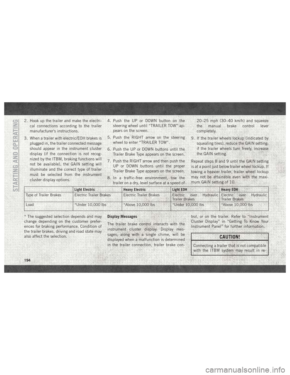
Light Electric Heavy ElectricLight EOHHeavy EOH
Type of Trailer Brakes Electric Trailer Brakes Electric Trailer Brakes Electric over Hydraulic Trailer BrakesElectric over Hydraulic
Trailer Brakes
Load *Under 10,000 lbs *Above 10,000 lbs *Under 10,000 lbs *Above 10,000 lbs
* The suggested selection depends and may
change depending on the customer prefer-
ences for braking performance. Condition of
the trailer brakes, driving and road state may
also affect the selection. Display Messages
The trailer brake control interacts with the
instrument cluster display. Display mes-
sages, along with a single chime, will be
displayed when a malfunction is determined
in the trailer connection, trailer brake con- trol, or on the trailer. Refer to “Instrument
Cluster Display” in “Getting To Know Your
Instrument Panel” for further information.
CAUTION!
Connecting a trailer that is not compatible
with the ITBM system may result in re-
STARTING AND OPERATING
194
Page 201 of 372

The NEUTRAL (N) indicator light will
blink while the shift is in progress. The
light will stop blinking (stay on solid)
when the shift to NEUTRAL (N) is com-
plete. After the shift is completed and
the NEUTRAL (N) light stays on, re-
lease the NEUTRAL (N) button.
6. Release the parking brake.
7. Shift the transmission into REVERSE.
8. Release the brake pedal (and clutch pedal on manual transmissions) for five seconds
and ensure that there is no vehicle
movement.
9. Repeat steps 7 and 8 with automatic transmission in DRIVE or manual trans-
mission in first gear.
10. Shift the transmission to NEUTRAL. Firmly apply the parking brake. Turn OFF
the engine. For vehicles with Keyless
Enter-N-Go, push and hold the ENGINE
START/STOP button until the engine
shuts off.
11. Shift the transmission into PARK or place manual transmission in gear (NOT in Neutral). On 8-speed transmissions
the shifter will automatically select
PARK when the engine is turned off.
12. Turn the ignition to the OFF mode, then cycle the ignition to the RUN mode and
back to the OFF mode. Remove the key
fob from the ignition.
13. Attach the vehicle to the tow vehicle using a suitable tow bar.
14. Release the parking brake.
NOTE:
With electronic shift transfer case:
• Steps 2 through 4 are requirements that must be met before pushing the NEUTRAL
(N) button, and must continue to be met
until the shift has been completed. If any of
these requirements are not met before
pushing the NEUTRAL (N) button or are no
longer met during the shift, the NEUTRAL
(N) indicator light will flash continuously
until all requirements are met or until the
NEUTRAL (N) button is released. • The ignition must be in the ON/RUN mode
for a shift to take place and for the position
indicator lights to be operable. If the igni-
tion is not in the ON/RUN mode, the shift
will not take place and no position indicator
lights will be on or flashing.
• A flashing NEUTRAL (N) position indicator light indicates that shift requirements have
not been met.
• If the vehicle is equipped with air suspen- sion, the engine should be started and left
running for a minimum of 60 seconds (with
all the doors closed) at least once every
24 hours. This process allows the air sus-
pension to adjust the vehicle’s ride height
to compensate for temperature effects.
Shifting Out Of NEUTRAL (N)
Use the following procedure to prepare your
vehicle for normal usage:
1. Bring the vehicle to a complete stop, leav-
ing it connected to the tow vehicle.
2. Firmly apply the parking brake.
3. Press and hold the brake pedal.
199
Page 202 of 372

4. Start the engine. Shift the transmissioninto NEUTRAL. Depress the clutch pedal
on a manual transmission.
• With manual shift transfer case, shift the transfer case lever to the desired
position.
• With electronic shift transfer case with rotary selector switch, push and hold
the transfer case NEUTRAL (N) button
until the NEUTRAL (N) indicator light
turns off. After the NEUTRAL (N) indi-
cator light turns off, release the NEU-
TRAL (N) button. After the NEUTRAL
(N) button has been released, the
transfer case will shift to the position
indicated by the selector switch.
• With electronic shift transfer case with push-button selector switch, push and
hold the switch for the desired transfer
case position, until the NEUTRAL (N)
indicator light turns off and the desired
position indicator light turns on. NOTE:
When shifting out of transfer case NEUTRAL
(N), turning the engine OFF is not required,
but may be helpful to avoid gear clash. With
the 8-speed automatic transmission, the en-
gine must remain running, since turning the
engine OFF will shift the transmission to
PARK (and the transmission must be in NEU-
TRAL for the transfer case to shift out of
NEUTRAL).
5. Turn the engine OFF. Shift automatic
transmission into PARK. On 8-speed
transmissions the shifter will automati-
cally select PARK when the engine is
turned off.
6. Release the brake pedal (and clutch pedal on a manual transmission).
7. Disconnect vehicle from the tow vehicle.
8. Start the engine.
9. Press and hold the brake pedal.
10. Release the parking brake.
11. Shift the transmission into gear, release the brake pedal (and clutch pedal on
manual transmissions), and check that
the vehicle operates normally. NOTE:
With electronic shift transfer case:
• Steps 3 and 4 are requirements that must
be met before pushing the button to shift
out of NEUTRAL (N), and must continue to
be met until the shift has been completed.
If any of these requirements are not met
before pushing the button or are no longer
met during the shift, the NEUTRAL (N)
indicator light will flash continuously until
all requirements are met or until the button
is released.
• The ignition must be in the ON/RUN mode for a shift to take place and for the position
indicator lights to be operable. If the igni-
tion is not in the ON/RUN mode, the shift
will not take place and no position indicator
lights will be on or flashing.
• A flashing NEUTRAL (N) position indicator light indicates that shift requirements have
not been met.
STARTING AND OPERATING
200