suspension Ram 3500 2018 Owner's Manual
[x] Cancel search | Manufacturer: RAM, Model Year: 2018, Model line: 3500, Model: Ram 3500 2018Pages: 372, PDF Size: 7.1 MB
Page 177 of 372

Normal Ride Height (NRH)– This is the stan-
dard position of the suspension and is meant
for normal driving. It will automatically adjust
to maintain the rear ride height as conditions
change.
Alternate Trailer Height (ATH) – Lowers the
vehicle approximately 1 in (25 mm) for a
level truck, to be used as required while
trailer towing. It will automatically adjust to
maintain the rear ride height as conditions
change.
Trailer Decoupling/Unloading - The air suspen-
sion system will load level (lower/exhaust
only) for up to 10 minutes after the vehicle is
turned off. This allows for easy removal of a trailer and/or load from the back of the truck
by maintaining the ride height. After 10 min-
utes you will need to turn the ignition to the
run position for the air suspension to main-
tain ride height. If the air suspension system
is disabled using the settings menu (Tire Jack
Mode, Transport Mode or Alignment Mode)
the system will remain disabled when the
vehicle is turned off. Reactivating the air
suspension can be accomplished via the set-
tings menu or driving the vehicle above
5 mph (8 km/h) for Tire Jack Mode or Align-
ment Mode and 16 mph (26 km/h) for Trans-
port Mode.
NOTE:
• Most 3500 models will not lower to Alter-
nate Trailer Height (ATH) when unloaded.
• Refer to “Trailer Towing” in “Starting And Operating” for further information.
Ignition OFF Behavior
For a predetermined amount of time after the
ignition is off the air suspension may adjust
to maintain a proper appearance.
Refer to your Owner’s Manual for further
information.
WARNING!
The air suspension system uses a high
pressure volume of air to operate the sys-
tem. To avoid personal injury or damage to
the system, see your authorized dealer for
service.
Air Suspension Modes
The air suspension system has multiple
modes to protect the system in unique situa-
tions:
Tire/Jack Mode
To assist with changing a tire, the air suspen-
sion system has a feature which allows the
automatic leveling to be disabled. This mode
is intended to be enabled with engine run-
ning. Refer to “Instrument Cluster Display”
in “Getting To Know Your Instrument Panel”
or “Uconnect Settings” in “Multimedia” if
equipped with a touch screen radio, in your
Owner’s Manual for further information.
NOTE:
This mode is intended to be enabled with
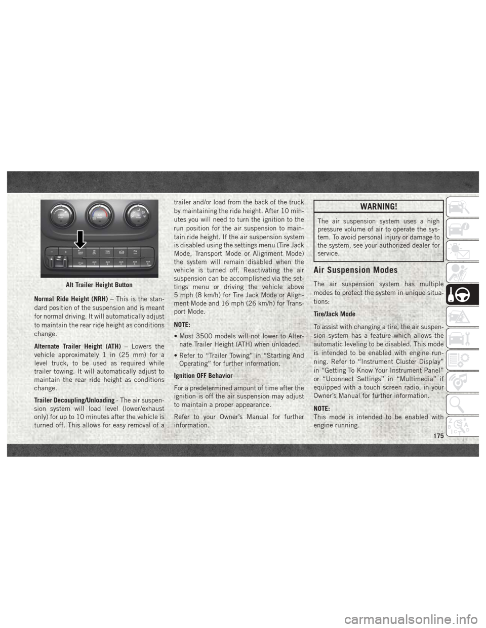
engine running.Alt Trailer Height Button
175
Page 178 of 372

Transport Mode
To assist with flat bed towing, the air suspen-
sion system has a feature which will put the
vehicle below Normal Ride Height (NRH) and
disable the automatic load leveling system.
This mode is intended to be enabled with
engine running. Refer to “Instrument Cluster
Display” in “Getting To Know Your Instru-
ment Panel” or “Uconnect Settings” in “Mul-
timedia” if equipped with a touch screen
radio, in your Owner’s Manual for further
information.
NOTE:
This mode is intended to be enabled with
engine running.
Wheel Alignment Mode
Before performing a wheel alignment this
mode must be enabled. Refer to “Instrument
Cluster Display” in “Getting To Know Your
Instrument Panel” or “Uconnect Settings” in
“Multimedia” if equipped with a touch
screen radio, in your Owner’s Manual for
further information.NOTE:
This mode is intended to be enabled with
engine running.
Protection Strategy
In order to “protect” the air suspension sys-
tem, the vehicle will disable load leveling as
required (suspension overloaded, battery
charge low, etc.). Load leveling will automati-
cally resume as soon as system operation
requirements are met. See your authorized
dealer if system does not resume.
SPEED CONTROL
When engaged, the Speed Control takes over
accelerator operations at speeds greater than
25 mph (40 km/h).
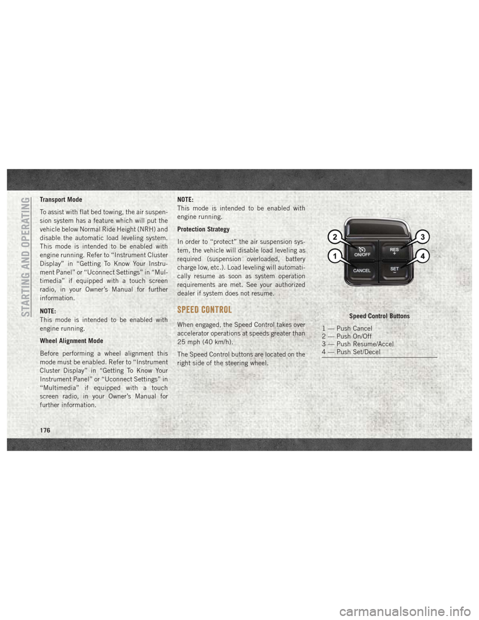
The Speed Control buttons are located on the
right side of the steering wheel.
Speed Control Buttons
1 — Push Cancel
2 — Push On/Off
3 — Push Resume/Accel
4 — Push Set/Decel
STARTING AND OPERATING
176
Page 193 of 372

TRAILER TOWING
Trailer Towing Weights (Maximum
Trailer Weight Ratings)
NOTE:
For trailer towing information (maximum
trailer weight ratings) refer to the following
website addresses:
•ramtrucks.com/en/towing_guide/
• ramtruck.ca (Canada)
• rambodybuilder.com
Towing Requirements
To promote proper break-in of your new ve-
hicle drivetrain components, the following
guidelines are recommended.
CAUTION!
• Do not tow a trailer at all during the first
500 miles (805 km) the new vehicle is
driven. The engine, axle or other parts
could be damaged.
CAUTION!
• Then, during the first 500 miles(805 km) that a trailer is towed, do not
drive over 50 mph (80 km/h) and do not
make starts at full throttle. This helps
the engine and other parts of the vehicle
wear in at the heavier loads.
Perform the maintenance listed in the
“Scheduled Servicing”. Refer to “Scheduled
Servicing” in “Servicing And Maintenance”
for the proper maintenance intervals. When
towing a trailer, never exceed the GAWR or
GCWR ratings.
WARNING!
Improper towing can lead to a collision.
Follow these guidelines to make your
trailer towing as safe as possible:
• Make certain that the load is secured in the trailer and will not shift during travel.
When trailering cargo that is not fully
secured, dynamic load shifts can occur
that may be difficult for the driver to
WARNING!
control. You could lose control of your
vehicle and have a collision.
• When hauling cargo or towing a trailer,
do not overload your vehicle or trailer.
Overloading can cause a loss of control,
poor performance or damage to brakes,
axle, engine, transmission, steering,
suspension, chassis structure or tires.
• Safety chains must always be used be-
tween your vehicle and trailer. Always
connect the chains to the hook retainers
of the vehicle hitch. Cross the chains
under the trailer tongue and allow
enough slack for turning corners.
• Vehicles with trailers should not be
parked on a grade. When parking, apply
the parking brake on the tow vehicle. Put
the tow vehicle transmission in PARK.
For four-wheel drive vehicles, make sure
the transfer case is not in NEUTRAL.
Always, block or "chock" the trailer
wheels.
• GCWR must not be exceeded.
191
Page 198 of 372

RECREATIONAL TOWING (BEHIND MOTORHOME, ETC.)
Towing This Vehicle Behind Another Vehicle
Towing ConditionWheels OFF The
Ground Two-Wheel Drive
Models Four-Wheel Drive Models
Flat Tow NONENOT ALLOWED See Instructions
• Automatic transmission in PARK
• Manual transmission in gear (NOT in NEUTRAL)
• Transfer case in NEUTRAL (N)
• Tow in forward direction
Dolly Tow Front
NOT ALLOWED
NOT ALLOWED
Rear OK NOT ALLOWED
On Trailer ALLOK OK
NOTE:
• When towing your vehicle, always follow
applicable state and provincial laws. Con-
tact state and provincial Highway Safety
offices for additional details. • Vehicles equipped with air suspension
must be placed in Transport mode before
tying them down (from the body) on a trailer
or flatbed truck. Refer to “Air Suspension –
If Equipped” for more information. If the
vehicle cannot be placed in Transport mode
(for example, engine will not run), tie-
downs must be fastened to the axles (not to
the body). Failure to follow these instruc-
tions may cause fault codes to be set and/or
cause loss of proper tie-down tension.STARTING AND OPERATING
196
Page 199 of 372

Recreational Towing —
Two-Wheel Drive Models
DO NOT flat tow this vehicle. Damage to the
drivetrain will result.
Recreational towing (for two-wheel drive
models) is allowedONLYif the rear wheels are
OFF the ground. This may be accomplished
using a tow dolly or vehicle trailer. If using a
tow dolly, follow this procedure:
NOTE:
If vehicle is equipped with air suspension,
ensure the vehicle is set to Normal Ride
Height.
1. Properly secure the dolly to the tow ve- hicle, following the dolly manufacturer's
instructions.
2. Drive the rear wheels onto the tow dolly. 3. Firmly apply the parking brake. Place au-
tomatic transmission in PARK, manual
transmission in gear (not in NEUTRAL).
4. Properly secure the rear wheels to the dolly, following the dolly manufacturer's
instructions.
5. Turn the ignition OFF and remove the key fob.
6. Install a suitable clamping device, de- signed for towing, to secure the front
wheels in the straight position.
CAUTION!
• Towing with the rear wheels on theground will cause severe transmission
damage. Damage from improper towing
is not covered under the New Vehicle
Limited Warranty.
• Do not disconnect the driveshaft be-
cause fluid may leak from the transmis-
sion, causing damage to internal parts.
Recreational Towing —
Four-Wheel Drive Models
NOTE:
Both the manual shift and electronic shift
transfer cases must be shifted into NEUTRAL
(N) for recreational towing. Automatic trans-
missions must be shifted into PARK for rec-
reational towing. Manual transmissions must
be placed in gear (NOT in NEUTRAL) for
recreational towing. Refer to the following for
the proper transfer case NEUTRAL (N) shift-
ing procedure for your vehicle.
CAUTION!
• DO NOT dolly tow any 4WD vehicle.Towing with only one set of wheels on the
ground (front or rear) will cause severe
transmission and/or transfer case dam-
age. Tow with all four wheels either ON
the ground, or OFF the ground (using a
vehicle trailer).
• Tow only in the forward direction. Towing
this vehicle backwards can cause severe
damage to the transfer case.
197
Page 200 of 372

CAUTION!
• Before recreational towing, the transfercase must be in NEUTRAL. To be certain
the transfer case is fully in NEUTRAL,
perform the procedure outlined under
“Shifting Into NEUTRAL”. Internal
transmission damage will result, if the
transfer case is not in NEUTRAL during
towing.
• Automatic transmissions must be
placed in PARK, and manual transmis-
sions must be placed in gear (not in
Neutral) for recreational towing.
• Towing this vehicle in violation of the
above requirements can cause severe
transmission and/or transfer case dam-
age. Damage from improper towing is
not covered under the New Vehicle Lim-
ited Warranty.
• Do not disconnect the rear driveshaft
because fluid will leak from the transfer
case, causing damage to internal parts.
• Do not use a bumper-mounted clamp-on
tow bar on your vehicle. The bumper
face bar will be damaged.
Shifting Into NEUTRAL (N)
Use the following procedure to prepare your
vehicle for recreational towing.
WARNING!
You or others could be injured or killed if
you leave the vehicle unattended with the
transfer case in the NEUTRAL (N) position
without first fully engaging the parking
brake. The transfer case NEUTRAL (N)
position disengages both the front and rear
driveshafts from the powertrain, and will
allow the vehicle to roll, even if the auto-
matic transmission is in PARK (or manual
transmission is in gear). The parking brake
should always be applied when the driver
is not in the vehicle.
CAUTION!
It is necessary to follow these steps to be
certain that the transfer case is fully in
NEUTRAL (N) before recreational towing
to prevent damage to internal parts. 1. Bring the vehicle to a complete stop on
level ground, with the engine running.
Firmly apply the parking brake.
2. Shift the transmission to NEUTRAL.
NOTE:
If vehicle is equipped with air suspension,
ensure the vehicle is set to Normal Ride
Height.
3. Press and hold the brake pedal.
4. Depress the clutch pedal on a manual transmission.
5. Shift the transfer case into NEUTRAL:
• With manual shift transfer case, shiftthe transfer case lever into NEUTRAL
(N)
• With electronic shift transfer case, push and hold the transfer case NEU-
TRAL (N) button. Some models have a
small, recessed “N” button (at the cen-
ter of the transfer case switches) that
must be pushed using a ballpoint pen
or similar object. Other models have a
rectangular NEUTRAL switch, below
the rotary transfer case control knob.
STARTING AND OPERATING
198
Page 205 of 372

Bulb Number
Premium Backup
Lamp 7440/W21W
Rear Lamp Bar ID
Marker Lamp 194
Side Marker Lamps
(Dual Rear Wheels) 194
Backup Lamp 921
Rear License Plate
Lamp 194
FUSES
WARNING!
• When replacing a blown fuse, always use
an appropriate replacement fuse with
the same amp rating as the original fuse.
Never replace a fuse with another fuse of
WARNING!
higher amp rating. Never replace a
blown fuse with metal wires or any other
material. Do not place a fuse inside a
circuit breaker cavity or vice versa. Fail-
ure to use proper fuses may result in
serious personal injury, fire and/or prop-
erty damage.
• Before replacing a fuse, make sure that
the ignition is off and that all the other
services are switched off and/or disen-
gaged.
• If the replaced fuse blows again, contact
an authorized dealer.
• If a general protection fuse for safety
systems (air bag system, braking sys-
tem), power unit systems (engine sys-
tem, transmission system) or steering
WARNING!
system blows, contact an authorized
dealer.
Power Distribution Center
The Power Distribution Center is located in
the engine compartment near the battery.
This center contains cartridge fuses, micro
fuses, relays, and circuit breakers. A descrip-
tion of each fuse and component may be
stamped on the inside cover, otherwise the
cavity number of each fuse is stamped on the
inside cover that corresponds to the following
chart.
Cavity Cartridge Fuse Micro Fuse Description
F01 80 Amp Black –Rad Fan Control Module – If Equipped
F03 60 Amp Yellow –Rad Fan – If Equipped
F05 40 Amp Green –Compressor for Air Suspension – If Equipped
F06 40 Amp Green –Antilock Brakes/Electronic Stability Control Pump
203
Page 207 of 372

CavityCartridge Fuse Micro Fuse Description
F25 30 Amp Pink – Front Wiper
F26 30 Amp Pink –Antilock Brakes / Stability Control Module / Valves
F28 20 Amp Blue –Trailer Tow Backup Lights – If Equipped
F29 20 Amp Blue –Trailer Tow Parking Lights – If Equipped
F30 30 Amp Pink –Trailer Tow Receptacle
F31 30 Amp Pink (1500 LD
Diesel) –
Urea Heater Control – If Equipped
F32 –– Spare Fuse
F33 20 Amp Blue –Special Services Vehicle Only
F34 30 Amp Pink –Vehicle System Interface Module #2 – If Equipped
F35 30 Amp Pink –Sunroof – If Equipped
F36 30 Amp Pink –Rear Defroster – If Equipped
F37 30 Amp Pink –Cummins Diesel Fuel Heater #2 – If Equipped
F38 30 Amp Pink –Power Inverter 115V AC – If Equipped
F39 20 Amp Blue –Power Outlet – Special Services Only
F41 –10 Amp Red Active Grill Shutter – If Equipped
F42 –20 Amp Yellow Horn
F44 –10 Amp Red Diagnostic Port
F46 –10 Amp Red Upfitter – If Equipped
F49 –10 Amp Red Instrument Panel Cluster (Except Fleet Vehicles)
F50 –20 Amp Yellow Air Suspension Control Module – If Equipped
F51 –10 Amp Red Ignition Node Module / Keyless Ignition (Instrument
Panel Cluster – Fleet Vehicles Only)
205
Page 209 of 372

CavityCartridge Fuse Micro Fuse Description
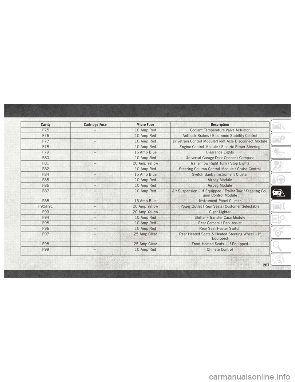
F75 –10 Amp Red Coolant Temperature Valve Actuator
F76 –10 Amp Red Antilock Brakes / Electronic Stability Control
F77 –10 Amp Red Drivetrain Control Module/Front Axle Disconnect Module
F78 –10 Amp Red Engine Control Module / Electric Power Steering
F79 –15 Amp Blue Clearance Lights
F80 –10 Amp Red Universal Garage Door Opener / Compass
F81 –20 Amp Yellow Trailer Tow Right Turn / Stop Lights
F82 –10 Amp Red Steering Column Control Module / Cruise Control
F84 –15 Amp Blue Switch Bank / Instrument Cluster
F85 –10 Amp Red Airbag Module
F86 –10 Amp Red Airbag Module
F87 –10 Amp Red Air Suspension – If Equipped / Trailer Tow / Steering Col-
umn Control Module
F88 –15 Amp Blue Instrument Panel Cluster
F90/F91 –20 Amp Yellow Power Outlet (Rear Seats) Customer Selectable
F93 –20 Amp Yellow Cigar Lighter
F94 –10 Amp Red Shifter / Transfer Case Module
F95 –10 Amp Red Rear Camera / Park Assist
F96 –10 Amp Red Rear Seat Heater Switch
F97 –25 Amp Clear Rear Heated Seats & Heated Steering Wheel – If
Equipped
F98 –25 Amp Clear Front Heated Seats – If Equipped
F99 –10 Amp Red Climate Control
207
Page 227 of 372

TOWING A DISABLED VEHICLE
This section describes procedures for towing
a disabled vehicle using a commercial towing
service. If the transmission and drivetrain are
operable, disabled vehicles may also be
towed as described under “Recreational Tow-
ing” in the “Starting And Operating” section.NOTE:
Vehicles equipped with air suspension must
be placed in Transport mode, before tying
them down (from the body) on a trailer or
flatbed truck. Refer to "Air Suspension" in
"Starting And Operating" for more informa-
tion. If the vehicle cannot be placed in Trans-
port mode (for example, engine will not run),
tie-downs must be fastened to the axles (not
to the body). Failure to follow these instruc-
tions may cause fault codes to be set and/or
cause loss of proper tie-down tension.
Towing Condition Wheels OFF The Ground
2WD Models4WD Models
Flat Tow NONE If transmission is operable:
• Transmission in NEUTRAL
• 30 mph (48 km/h) max
• 15 miles (24 km) maxdistance •
Auto Transmission in PARK
• Manual Transmission in gear
(NOT NEUTRAL)
• Transfer Case in NEUTRAL
• Tow in FORWARDdirection
Wheel Lift Or Dolly Tow Front
NOT ALLOWED
Rear OK
NOT ALLOWED
Flatbed ALL
BEST METHOD BEST METHOD
CAUTION!
• Do not use sling type equipment when
towing. Vehicle damage may occur.
CAUTION!
•When securing the vehicle to a flat bed
truck, do not attach to front or rear sus-
CAUTION!
pension components. Damage to your ve-
hicle may result from improper towing.
225