towing Ram 3500 2018 Owner's Manual
[x] Cancel search | Manufacturer: RAM, Model Year: 2018, Model line: 3500, Model: Ram 3500 2018Pages: 372, PDF Size: 7.1 MB
Page 173 of 372

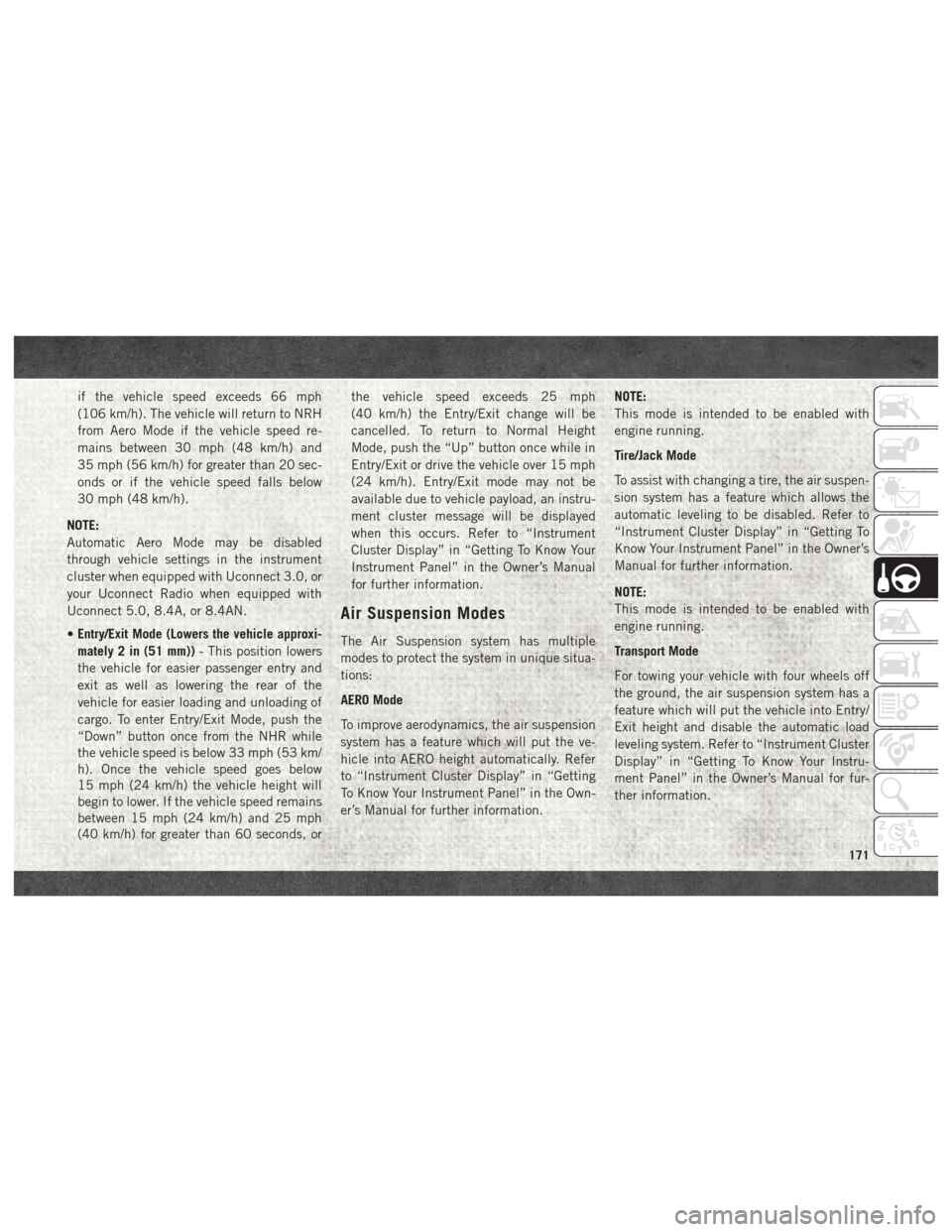
if the vehicle speed exceeds 66 mph
(106 km/h). The vehicle will return to NRH
from Aero Mode if the vehicle speed re-
mains between 30 mph (48 km/h) and
35 mph (56 km/h) for greater than 20 sec-
onds or if the vehicle speed falls below
30 mph (48 km/h).
NOTE:
Automatic Aero Mode may be disabled
through vehicle settings in the instrument
cluster when equipped with Uconnect 3.0, or
your Uconnect Radio when equipped with
Uconnect 5.0, 8.4A, or 8.4AN.
• Entry/Exit Mode (Lowers the vehicle approxi-
mately 2 in (51 mm)) - This position lowers
the vehicle for easier passenger entry and
exit as well as lowering the rear of the
vehicle for easier loading and unloading of
cargo. To enter Entry/Exit Mode, push the
“Down” button once from the NHR while
the vehicle speed is below 33 mph (53 km/
h). Once the vehicle speed goes below
15 mph (24 km/h) the vehicle height will
begin to lower. If the vehicle speed remains
between 15 mph (24 km/h) and 25 mph
(40 km/h) for greater than 60 seconds, or the vehicle speed exceeds 25 mph
(40 km/h) the Entry/Exit change will be
cancelled. To return to Normal Height
Mode, push the “Up” button once while in
Entry/Exit or drive the vehicle over 15 mph
(24 km/h). Entry/Exit mode may not be
available due to vehicle payload, an instru-
ment cluster message will be displayed
when this occurs. Refer to “Instrument
Cluster Display” in “Getting To Know Your
Instrument Panel” in the Owner’s Manual
for further information.
Air Suspension Modes
The Air Suspension system has multiple
modes to protect the system in unique situa-
tions:
AERO Mode
To improve aerodynamics, the air suspension
system has a feature which will put the ve-
hicle into AERO height automatically. Refer
to “Instrument Cluster Display” in “Getting
To Know Your Instrument Panel” in the Own-
er’s Manual for further information.
NOTE:
This mode is intended to be enabled with
engine running.
Tire/Jack Mode
To assist with changing a tire, the air suspen-
sion system has a feature which allows the
automatic leveling to be disabled. Refer to
“Instrument Cluster Display” in “Getting To
Know Your Instrument Panel” in the Owner’s
Manual for further information.
NOTE:
This mode is intended to be enabled with
engine running.
Transport Mode
For towing your vehicle with four wheels off
the ground, the air suspension system has a
feature which will put the vehicle into Entry/
Exit height and disable the automatic load
leveling system. Refer to “Instrument Cluster
Display” in “Getting To Know Your Instru-
ment Panel” in the Owner’s Manual for fur-
ther information.
171
Page 174 of 372

NOTE:
This mode is intended to be enabled with
engine running.
Wheel Alignment Mode
Before performing a wheel alignment, this
mode must be enabled. Refer to “Instrument
Cluster Display” in “Getting To Know Your
Instrument Panel” in the Owner’s Manual for
further information.
NOTE:
This mode is intended to be enabled with
engine running.
Protection Strategy
In order to “protect” the air suspension sys-
tem, the vehicle will disable load leveling as
required (suspension overloaded, battery
charge low, etc.). Load leveling will automati-
cally resume as soon as system operation
requirements are met. See your authorized
dealer if system does not resume.
NOTE:
If towing with air suspension refer to “Trailer
Towing” in “Starting And Operating” for fur-
ther information.AIR SUSPENSION SYSTEM (REBEL
MODELS ONLY) — IF EQUIPPED
Description
The air suspension system provides full time
load leveling capability along with the benefit
of being able to adjust vehicle height by the
push of a button.
Automatic height changes will occur based
on vehicle speed and the current vehicle
height. The indicator lamps and instrument
cluster messages will operate the same for
automatic changes and user requested
changes.NOTE:
The vehicle will automatically enter Aero Mode
when the vehicle speed remains between
62 mph (100 km/h) and 66 mph (106 km/h)
for greater than 20 seconds or if the vehicle
speed exceeds 66 mph (106 km/h).
Rebel Air Suspension Controls
1 — Normal Ride Height Indicator
Lamp
2 — Off-Road Indicator Lamp
3 — Up Button
4 — Down Button
5 — Entry/Exit Mode Indicator Lamp
6 — Aero Mode Indicator Lamp
STARTING AND OPERATING
172
Page 176 of 372

to “Instrument Cluster Display” in “Getting
To Know Your Instrument Panel” in the Own-
er’s Manual for further information.
NOTE:
This mode is intended to be enabled with
engine running.
Tire/Jack Mode
To assist with changing a tire, the air suspen-
sion system has a feature which allows the
automatic leveling to be disabled. Refer to
“Instrument Cluster Display” in “Getting To
Know Your Instrument Panel” in the Owner’s
Manual for further information.
NOTE:
This mode is intended to be enabled with
engine running.
Transport Mode
For towing your vehicle with four wheels off
the ground, the air suspension system has a
feature which will put the vehicle into Entry/
Exit height and disable the automatic loadleveling system. Refer to “Instrument Cluster
Display” in “Getting To Know Your Instru-
ment Panel” in the Owner’s Manual for fur-
ther information.
NOTE:
This mode is intended to be enabled with
engine running.
Wheel Alignment Mode
Before performing a wheel alignment, this
mode must be enabled. Refer to “Instrument
Cluster Display” in “Getting To Know Your
Instrument Panel” in the Owner’s Manual for
further information.
NOTE:
This mode is intended to be enabled with
engine running.
Protection Strategy
In order to “protect” the air suspension sys-
tem, the vehicle will disable load leveling as
required (suspension overloaded, battery
charge low, etc.). Load leveling will automati-
cally resume as soon as system operation
requirements are met. See your authorized
dealer if system does not resume. NOTE:
If towing with air suspension refer to “Trailer
Towing” in “Starting And Operating” for fur-
ther information.
AIR SUSPENSION SYSTEM
(2500/3500 MODELS) — IF
EQUIPPED
Description
This air suspension system is a rear leveling
ride height system. The main purpose of this
system is to maintain the truck’s rear ride
height level. There are two selectable heights
that can be chosen based on your operating
conditions.
The system requires that the ignition be in
ON/RUN position or the engine running with
zero vehicle speed for all user requested
changes and load leveling.
STARTING AND OPERATING
174
Page 177 of 372

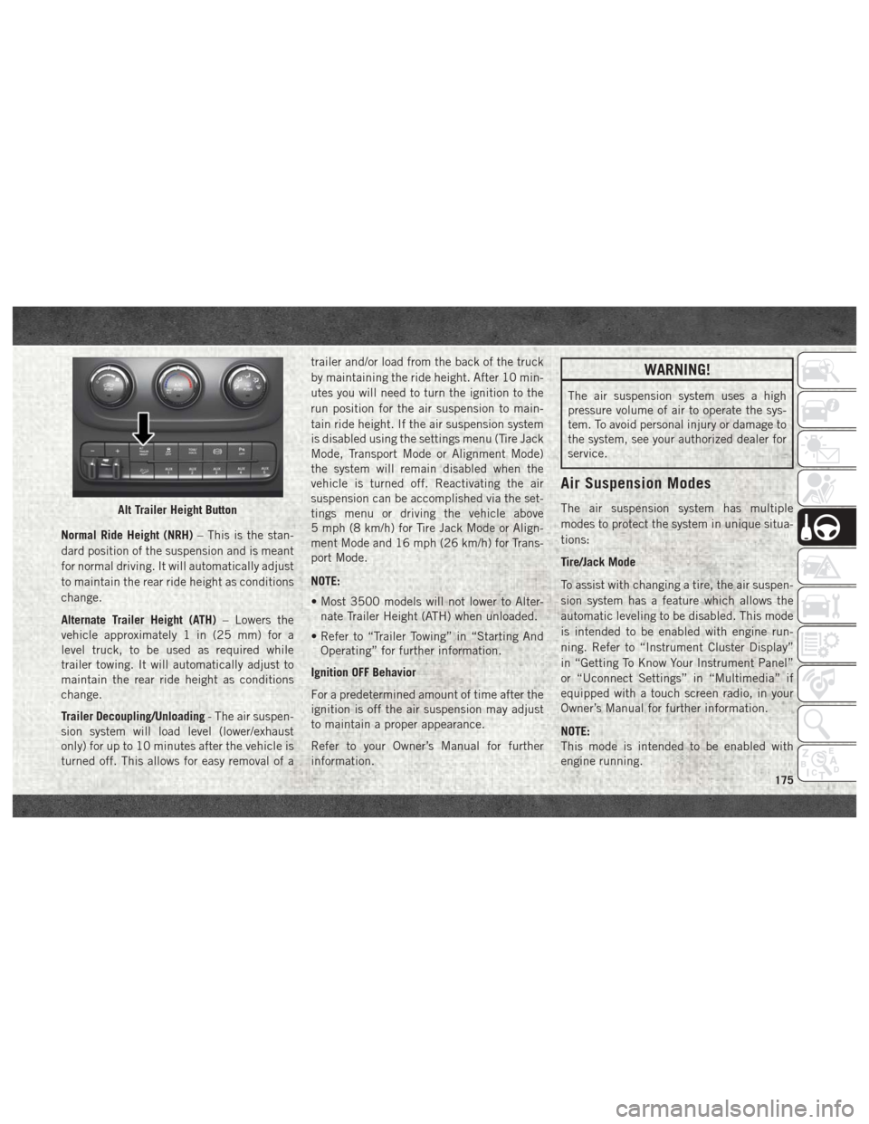
Normal Ride Height (NRH)– This is the stan-
dard position of the suspension and is meant
for normal driving. It will automatically adjust
to maintain the rear ride height as conditions
change.
Alternate Trailer Height (ATH) – Lowers the
vehicle approximately 1 in (25 mm) for a
level truck, to be used as required while
trailer towing. It will automatically adjust to
maintain the rear ride height as conditions
change.
Trailer Decoupling/Unloading - The air suspen-
sion system will load level (lower/exhaust
only) for up to 10 minutes after the vehicle is
turned off. This allows for easy removal of a trailer and/or load from the back of the truck
by maintaining the ride height. After 10 min-
utes you will need to turn the ignition to the
run position for the air suspension to main-
tain ride height. If the air suspension system
is disabled using the settings menu (Tire Jack
Mode, Transport Mode or Alignment Mode)
the system will remain disabled when the
vehicle is turned off. Reactivating the air
suspension can be accomplished via the set-
tings menu or driving the vehicle above
5 mph (8 km/h) for Tire Jack Mode or Align-
ment Mode and 16 mph (26 km/h) for Trans-
port Mode.
NOTE:
• Most 3500 models will not lower to Alter-
nate Trailer Height (ATH) when unloaded.
• Refer to “Trailer Towing” in “Starting And Operating” for further information.
Ignition OFF Behavior
For a predetermined amount of time after the
ignition is off the air suspension may adjust
to maintain a proper appearance.
Refer to your Owner’s Manual for further
information.
WARNING!
The air suspension system uses a high
pressure volume of air to operate the sys-
tem. To avoid personal injury or damage to
the system, see your authorized dealer for
service.
Air Suspension Modes
The air suspension system has multiple
modes to protect the system in unique situa-
tions:
Tire/Jack Mode
To assist with changing a tire, the air suspen-
sion system has a feature which allows the
automatic leveling to be disabled. This mode
is intended to be enabled with engine run-
ning. Refer to “Instrument Cluster Display”
in “Getting To Know Your Instrument Panel”
or “Uconnect Settings” in “Multimedia” if
equipped with a touch screen radio, in your
Owner’s Manual for further information.
NOTE:
This mode is intended to be enabled with
engine running.Alt Trailer Height Button
175
Page 178 of 372

Transport Mode
To assist with flat bed towing, the air suspen-
sion system has a feature which will put the
vehicle below Normal Ride Height (NRH) and
disable the automatic load leveling system.
This mode is intended to be enabled with
engine running. Refer to “Instrument Cluster
Display” in “Getting To Know Your Instru-
ment Panel” or “Uconnect Settings” in “Mul-
timedia” if equipped with a touch screen
radio, in your Owner’s Manual for further
information.
NOTE:
This mode is intended to be enabled with
engine running.
Wheel Alignment Mode
Before performing a wheel alignment this
mode must be enabled. Refer to “Instrument
Cluster Display” in “Getting To Know Your
Instrument Panel” or “Uconnect Settings” in
“Multimedia” if equipped with a touch
screen radio, in your Owner’s Manual for
further information.NOTE:
This mode is intended to be enabled with
engine running.
Protection Strategy
In order to “protect” the air suspension sys-
tem, the vehicle will disable load leveling as
required (suspension overloaded, battery
charge low, etc.). Load leveling will automati-
cally resume as soon as system operation
requirements are met. See your authorized
dealer if system does not resume.
SPEED CONTROL
When engaged, the Speed Control takes over
accelerator operations at speeds greater than
25 mph (40 km/h).
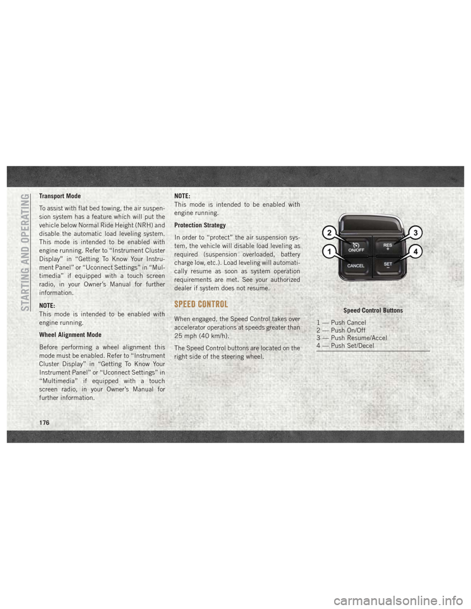
The Speed Control buttons are located on the
right side of the steering wheel.
Speed Control Buttons
1 — Push Cancel
2 — Push On/Off
3 — Push Resume/Accel
4 — Push Set/Decel
STARTING AND OPERATING
176
Page 193 of 372

TRAILER TOWING
Trailer Towing Weights (Maximum
Trailer Weight Ratings)
NOTE:
For trailer towing information (maximum
trailer weight ratings) refer to the following
website addresses:
•ramtrucks.com/en/towing_guide/
• ramtruck.ca (Canada)
• rambodybuilder.com
Towing Requirements
To promote proper break-in of your new ve-
hicle drivetrain components, the following
guidelines are recommended.
CAUTION!
• Do not tow a trailer at all during the first
500 miles (805 km) the new vehicle is
driven. The engine, axle or other parts
could be damaged.
CAUTION!
• Then, during the first 500 miles(805 km) that a trailer is towed, do not
drive over 50 mph (80 km/h) and do not
make starts at full throttle. This helps
the engine and other parts of the vehicle
wear in at the heavier loads.
Perform the maintenance listed in the
“Scheduled Servicing”. Refer to “Scheduled
Servicing” in “Servicing And Maintenance”
for the proper maintenance intervals. When
towing a trailer, never exceed the GAWR or
GCWR ratings.
WARNING!
Improper towing can lead to a collision.
Follow these guidelines to make your
trailer towing as safe as possible:
• Make certain that the load is secured in the trailer and will not shift during travel.
When trailering cargo that is not fully
secured, dynamic load shifts can occur
that may be difficult for the driver to
WARNING!
control. You could lose control of your
vehicle and have a collision.
• When hauling cargo or towing a trailer,
do not overload your vehicle or trailer.
Overloading can cause a loss of control,
poor performance or damage to brakes,
axle, engine, transmission, steering,
suspension, chassis structure or tires.
• Safety chains must always be used be-
tween your vehicle and trailer. Always
connect the chains to the hook retainers
of the vehicle hitch. Cross the chains
under the trailer tongue and allow
enough slack for turning corners.
• Vehicles with trailers should not be
parked on a grade. When parking, apply
the parking brake on the tow vehicle. Put
the tow vehicle transmission in PARK.
For four-wheel drive vehicles, make sure
the transfer case is not in NEUTRAL.
Always, block or "chock" the trailer
wheels.
• GCWR must not be exceeded.
191
Page 194 of 372

WARNING!
•Total weight must be distributed between
the tow vehicle and the trailer such that the
following four ratings are not exceeded:
1. GVWR
2. GTW
3. GAWR
4. Tongue weight rating for the trailer hitch utilized.
Towing Requirements — Trailer Brakes
•Do notinterconnect the hydraulic brake
system or vacuum system of your vehicle
with that of the trailer. This could cause
inadequate braking and possible personal
injury.
• An electronically actuated trailer brake controller is required when towing a trailer
with electronically actuated brakes. When
towing a trailer equipped with a hydraulic
surge actuated brake system, an electronic
brake controller is not required. • Trailer brakes are recommended for trailers
over 1,000 lbs (453 kg) and required for
trailers in excess of 2,000 lbs (907 kg).
WARNING!
•Do not connect trailer brakes to your ve-
hicle's hydraulic brake lines. It can over-
load your brake system and cause it to
fail. You might not have brakes when you
need them and could have a collision.
• Towing any trailer will increase your stopping distance. When towing you
should allow for additional space be-
tween your vehicle and the vehicle in
front of you. Failure to do so could result
in a collision.
CAUTION!
If the trailer weighs more than 1,000 lbs
(453 kg) loaded, it should have its own
brakes and they should be of adequate
capacity. Failure to do this could lead to
accelerated brake lining wear, higher
brake pedal effort, and longer stopping
distances.
Integrated Trailer Brake Module — If
Equipped
Your vehicle may have an Integrated Trailer
Brake Module (ITBM) for Electric and Elec-
tric Over Hydraulic (EOH) trailer brakes.
NOTE:
This module has been designed and verified
with electric trailer brakes and new electric
over hydraulic systems. Some previous EOH
systems may not be compatible with ITBM.
STARTING AND OPERATING
192
Page 195 of 372

The user interface consists of the following:
Manual Brake Control Lever
Slide the manual brake control lever to the
left to activate power to the trailer's electric
brakes independent of the tow vehicle's
brakes. If the manual brake control lever isactivated while the brake is also applied, the
greater of the two inputs determines the
power sent to the trailer brakes.
The trailer and the vehicle's brake lamps will
come on when either vehicle braking or
manual trailer brakes are applied.
Trailer Brake Status Indicator Light
This light indicates the trailer electrical con-
nection status.
If no electrical connection is detected after
the ignition is turned on, pushing the GAIN
adjustment button or sliding the manual
brake control lever will display the GAIN
setting for 10 seconds and the “Trailer Brake
Status Indicator Light” will not be displayed.
If a fault is detected in the trailer wiring or the
Integrated Trailer Brake Module (ITBM), the
“Trailer Brake Status Indicator Light” will
flash.
GAIN Adjustment Buttons (+/-)
Pushing these buttons will adjust the brake
control power output to the trailer brakes in
0.5 increments. The GAIN setting can be
increased to a maximum of 10 or decreased
to a minimum of 0 (no trailer braking).
GAIN
The GAIN setting is used to set the trailer
brake control for the specific towing condi-
tion and should be changed as towing condi-
tions change. Changes to towing conditions
include trailer load, vehicle load, road condi-
tions and weather.
Adjusting GAIN
NOTE:
This should only be performed in a traffic free
environment at speeds of approximately 20–
25 mph (30–40 km/h).
1. Make sure the trailer brakes are in good
working condition, functioning normally
and properly adjusted. See your trailer
dealer if necessary.
Adjustment Buttons
1 — Decrease (-)
2 — Increase (+)
193
Page 196 of 372

2. Hook up the trailer and make the electri-cal connections according to the trailer
manufacturer's instructions.
3. When a trailer with electric/EOH brakes is plugged in, the trailer connected message
should appear in the instrument cluster
display (if the connection is not recog-
nized by the ITBM, braking functions will
not be available), the GAIN setting will
illuminate and the correct type of trailer
must be selected from the instrument
cluster display options. 4. Push the UP or DOWN button on the
steering wheel until “TRAILER TOW” ap-
pears on the screen.
5. Push the RIGHT arrow on the steering wheel to enter “TRAILER TOW”.
6. Push the UP or DOWN buttons until the Trailer Brake Type appears on the screen.
7. Push the RIGHT arrow and then push the UP or DOWN buttons until the proper
Trailer Brake Type appears on the screen.
8. In a traffic-free environment, tow the trailer on a dry, level surface at a speed of 20–25 mph (30–40 km/h) and squeeze
the manual brake control lever
completely.
9. If the trailer wheels lockup (indicated by squealing tires), reduce the GAIN setting;
if the trailer wheels turn freely, increase
the GAIN setting.
Repeat steps 8 and 9 until the GAIN setting
is at a point just below trailer wheel lockup. If
towing a heavier trailer, trailer wheel lockup
may not be attainable even with the maxi-
mum GAIN setting of 10.
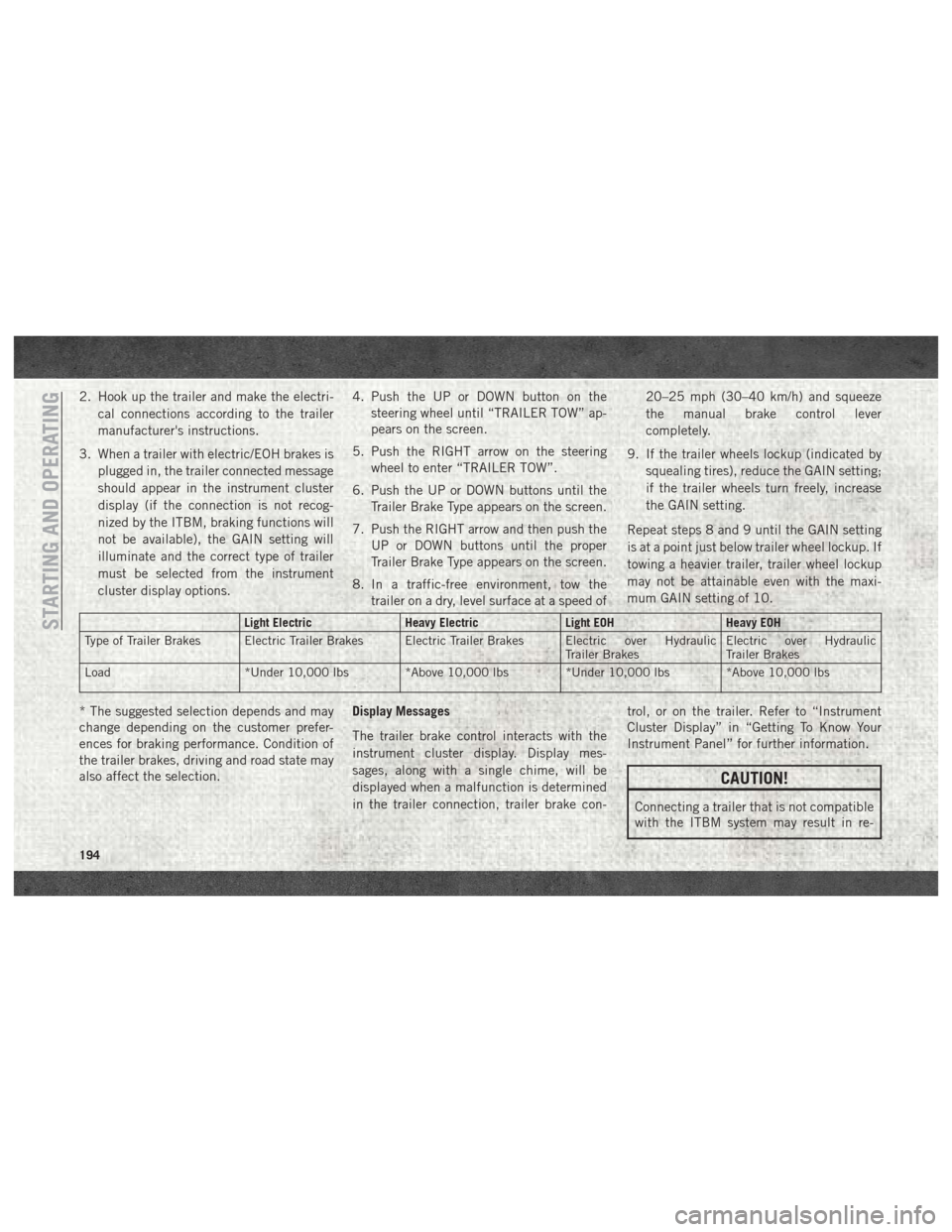
Light Electric Heavy ElectricLight EOHHeavy EOH
Type of Trailer Brakes Electric Trailer Brakes Electric Trailer Brakes Electric over Hydraulic Trailer BrakesElectric over Hydraulic
Trailer Brakes
Load *Under 10,000 lbs *Above 10,000 lbs *Under 10,000 lbs *Above 10,000 lbs
* The suggested selection depends and may
change depending on the customer prefer-
ences for braking performance. Condition of
the trailer brakes, driving and road state may
also affect the selection. Display Messages
The trailer brake control interacts with the
instrument cluster display. Display mes-
sages, along with a single chime, will be
displayed when a malfunction is determined
in the trailer connection, trailer brake con- trol, or on the trailer. Refer to “Instrument
Cluster Display” in “Getting To Know Your
Instrument Panel” for further information.
CAUTION!
Connecting a trailer that is not compatible
with the ITBM system may result in re-
STARTING AND OPERATING
194
Page 198 of 372

RECREATIONAL TOWING (BEHIND MOTORHOME, ETC.)
Towing This Vehicle Behind Another Vehicle
Towing ConditionWheels OFF The
Ground Two-Wheel Drive
Models Four-Wheel Drive Models
Flat Tow NONENOT ALLOWED See Instructions
• Automatic transmission in PARK
• Manual transmission in gear (NOT in NEUTRAL)
• Transfer case in NEUTRAL (N)
• Tow in forward direction
Dolly Tow Front
NOT ALLOWED
NOT ALLOWED
Rear OK NOT ALLOWED
On Trailer ALLOK OK
NOTE:
• When towing your vehicle, always follow
applicable state and provincial laws. Con-
tact state and provincial Highway Safety
offices for additional details. • Vehicles equipped with air suspension
must be placed in Transport mode before
tying them down (from the body) on a trailer
or flatbed truck. Refer to “Air Suspension –
If Equipped” for more information. If the
vehicle cannot be placed in Transport mode
(for example, engine will not run), tie-
downs must be fastened to the axles (not to
the body). Failure to follow these instruc-
tions may cause fault codes to be set and/or
cause loss of proper tie-down tension.STARTING AND OPERATING
196