parking brake Ram 3500 2018 Owner's Manual
[x] Cancel search | Manufacturer: RAM, Model Year: 2018, Model line: 3500, Model: Ram 3500 2018Pages: 372, PDF Size: 7.1 MB
Page 201 of 372

The NEUTRAL (N) indicator light will
blink while the shift is in progress. The
light will stop blinking (stay on solid)
when the shift to NEUTRAL (N) is com-
plete. After the shift is completed and
the NEUTRAL (N) light stays on, re-
lease the NEUTRAL (N) button.
6. Release the parking brake.
7. Shift the transmission into REVERSE.
8. Release the brake pedal (and clutch pedal on manual transmissions) for five seconds
and ensure that there is no vehicle
movement.
9. Repeat steps 7 and 8 with automatic transmission in DRIVE or manual trans-
mission in first gear.
10. Shift the transmission to NEUTRAL. Firmly apply the parking brake. Turn OFF
the engine. For vehicles with Keyless
Enter-N-Go, push and hold the ENGINE
START/STOP button until the engine
shuts off.
11. Shift the transmission into PARK or place manual transmission in gear (NOT in Neutral). On 8-speed transmissions
the shifter will automatically select
PARK when the engine is turned off.
12. Turn the ignition to the OFF mode, then cycle the ignition to the RUN mode and
back to the OFF mode. Remove the key
fob from the ignition.
13. Attach the vehicle to the tow vehicle using a suitable tow bar.
14. Release the parking brake.
NOTE:
With electronic shift transfer case:
• Steps 2 through 4 are requirements that must be met before pushing the NEUTRAL
(N) button, and must continue to be met
until the shift has been completed. If any of
these requirements are not met before
pushing the NEUTRAL (N) button or are no
longer met during the shift, the NEUTRAL
(N) indicator light will flash continuously
until all requirements are met or until the
NEUTRAL (N) button is released. • The ignition must be in the ON/RUN mode
for a shift to take place and for the position
indicator lights to be operable. If the igni-
tion is not in the ON/RUN mode, the shift
will not take place and no position indicator
lights will be on or flashing.
• A flashing NEUTRAL (N) position indicator light indicates that shift requirements have
not been met.
• If the vehicle is equipped with air suspen- sion, the engine should be started and left
running for a minimum of 60 seconds (with
all the doors closed) at least once every
24 hours. This process allows the air sus-
pension to adjust the vehicle’s ride height
to compensate for temperature effects.
Shifting Out Of NEUTRAL (N)
Use the following procedure to prepare your
vehicle for normal usage:
1. Bring the vehicle to a complete stop, leav-
ing it connected to the tow vehicle.
2. Firmly apply the parking brake.
3. Press and hold the brake pedal.
199
Page 202 of 372

4. Start the engine. Shift the transmissioninto NEUTRAL. Depress the clutch pedal
on a manual transmission.
• With manual shift transfer case, shift the transfer case lever to the desired
position.
• With electronic shift transfer case with rotary selector switch, push and hold
the transfer case NEUTRAL (N) button
until the NEUTRAL (N) indicator light
turns off. After the NEUTRAL (N) indi-
cator light turns off, release the NEU-
TRAL (N) button. After the NEUTRAL
(N) button has been released, the
transfer case will shift to the position
indicated by the selector switch.
• With electronic shift transfer case with push-button selector switch, push and
hold the switch for the desired transfer
case position, until the NEUTRAL (N)
indicator light turns off and the desired
position indicator light turns on. NOTE:
When shifting out of transfer case NEUTRAL
(N), turning the engine OFF is not required,
but may be helpful to avoid gear clash. With
the 8-speed automatic transmission, the en-
gine must remain running, since turning the
engine OFF will shift the transmission to
PARK (and the transmission must be in NEU-
TRAL for the transfer case to shift out of
NEUTRAL).
5. Turn the engine OFF. Shift automatic
transmission into PARK. On 8-speed
transmissions the shifter will automati-
cally select PARK when the engine is
turned off.
6. Release the brake pedal (and clutch pedal on a manual transmission).
7. Disconnect vehicle from the tow vehicle.
8. Start the engine.
9. Press and hold the brake pedal.
10. Release the parking brake.
11. Shift the transmission into gear, release the brake pedal (and clutch pedal on
manual transmissions), and check that
the vehicle operates normally. NOTE:
With electronic shift transfer case:
• Steps 3 and 4 are requirements that must
be met before pushing the button to shift
out of NEUTRAL (N), and must continue to
be met until the shift has been completed.
If any of these requirements are not met
before pushing the button or are no longer
met during the shift, the NEUTRAL (N)
indicator light will flash continuously until
all requirements are met or until the button
is released.
• The ignition must be in the ON/RUN mode for a shift to take place and for the position
indicator lights to be operable. If the igni-
tion is not in the ON/RUN mode, the shift
will not take place and no position indicator
lights will be on or flashing.
• A flashing NEUTRAL (N) position indicator light indicates that shift requirements have
not been met.
STARTING AND OPERATING
200
Page 207 of 372

CavityCartridge Fuse Micro Fuse Description
F25 30 Amp Pink – Front Wiper
F26 30 Amp Pink –Antilock Brakes / Stability Control Module / Valves
F28 20 Amp Blue –Trailer Tow Backup Lights – If Equipped
F29 20 Amp Blue –Trailer Tow Parking Lights – If Equipped
F30 30 Amp Pink –Trailer Tow Receptacle
F31 30 Amp Pink (1500 LD
Diesel) –
Urea Heater Control – If Equipped
F32 –– Spare Fuse
F33 20 Amp Blue –Special Services Vehicle Only
F34 30 Amp Pink –Vehicle System Interface Module #2 – If Equipped
F35 30 Amp Pink –Sunroof – If Equipped
F36 30 Amp Pink –Rear Defroster – If Equipped
F37 30 Amp Pink –Cummins Diesel Fuel Heater #2 – If Equipped
F38 30 Amp Pink –Power Inverter 115V AC – If Equipped
F39 20 Amp Blue –Power Outlet – Special Services Only
F41 –10 Amp Red Active Grill Shutter – If Equipped
F42 –20 Amp Yellow Horn
F44 –10 Amp Red Diagnostic Port
F46 –10 Amp Red Upfitter – If Equipped
F49 –10 Amp Red Instrument Panel Cluster (Except Fleet Vehicles)
F50 –20 Amp Yellow Air Suspension Control Module – If Equipped
F51 –10 Amp Red Ignition Node Module / Keyless Ignition (Instrument
Panel Cluster – Fleet Vehicles Only)
205
Page 212 of 372
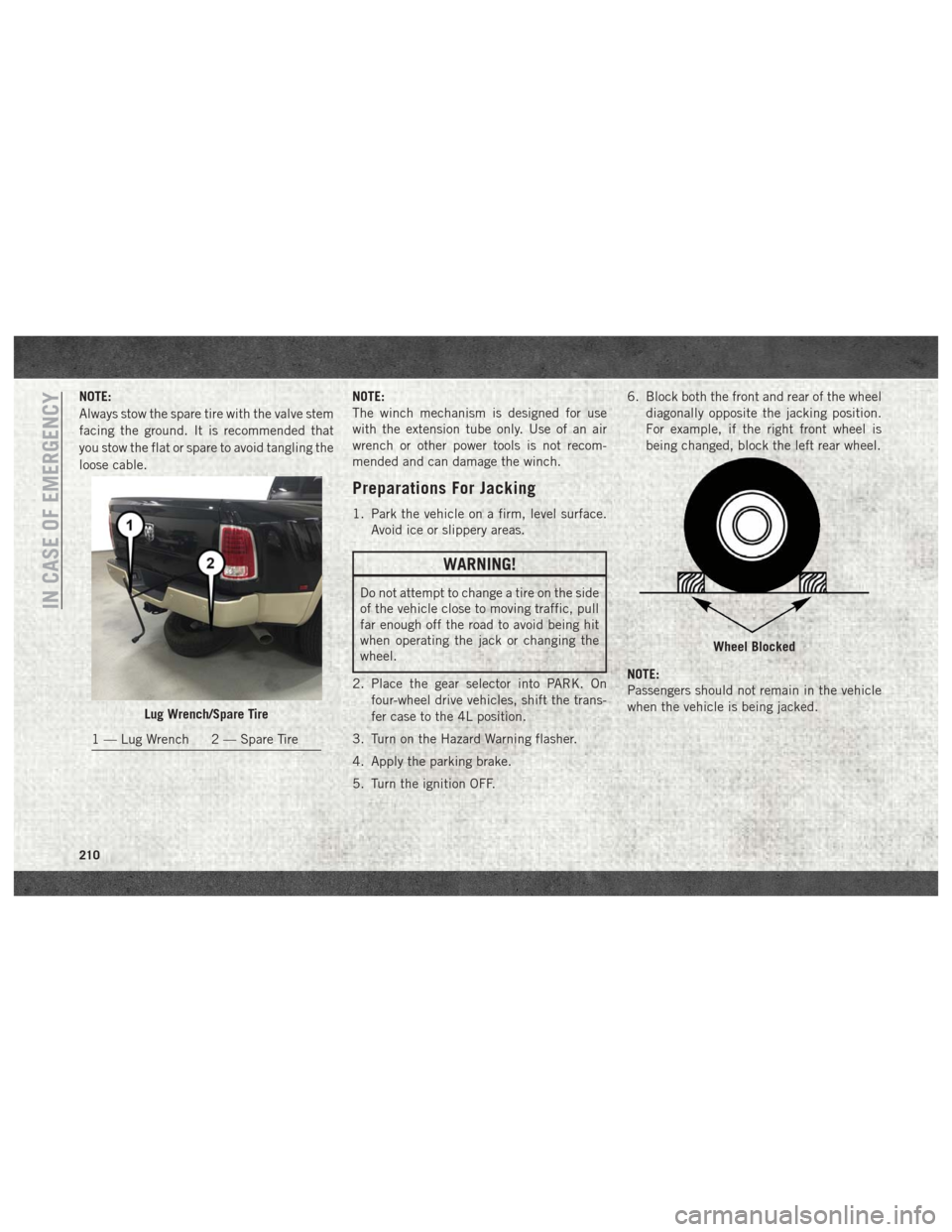
NOTE:
Always stow the spare tire with the valve stem
facing the ground. It is recommended that
you stow the flat or spare to avoid tangling the
loose cable.NOTE:
The winch mechanism is designed for use
with the extension tube only. Use of an air
wrench or other power tools is not recom-
mended and can damage the winch.
Preparations For Jacking
1. Park the vehicle on a firm, level surface.
Avoid ice or slippery areas.
WARNING!
Do not attempt to change a tire on the side
of the vehicle close to moving traffic, pull
far enough off the road to avoid being hit
when operating the jack or changing the
wheel.
2. Place the gear selector into PARK. On four-wheel drive vehicles, shift the trans-
fer case to the 4L position.
3. Turn on the Hazard Warning flasher.
4. Apply the parking brake.
5. Turn the ignition OFF. 6. Block both the front and rear of the wheel
diagonally opposite the jacking position.
For example, if the right front wheel is
being changed, block the left rear wheel.
NOTE:
Passengers should not remain in the vehicle
when the vehicle is being jacked.
Lug Wrench/Spare Tire
1 — Lug Wrench 2 — Spare Tire
Wheel Blocked
IN CASE OF EMERGENCY
210
Page 216 of 372
To Stow The Flat Or Spare
NOTE:
RAM 1500 vehicles equipped with alumi-
num wheels cannot be stored under the ve-
hicle because the wheel retainer will not fit
through the wheel pilot hole. Secure the flat
tire in the bed of the truck. Have the flat tire
repaired or replaced immediately.
1. Turn the wheel so that the valve stem isdown. Slide the wheel retainer through
the center of the wheel and position it
properly across the wheel opening.
2. For convenience in checking the spare tire inflation, stow with the valve stem toward
the rear of the vehicle.
3. Attach the lug wrench to the extension tubes with the curved angle facing away
from the vehicle. Rotate the lug wrench
handle clockwise until the wheel is drawn
into place against the underside of the
vehicle. Continue to rotate until you feel
the winch mechanism slip, or click three
or four times. It cannot be overtightened.
Push against the tire several times to be
sure it is firmly in place.
WARNING!
• Do not attempt to change a tire on theside of the vehicle close to moving traf-
fic. Pull far enough off the road to avoid
the danger of being hit when operating
the jack or changing the wheel.
• Being under a jacked-up vehicle is dan-
gerous. The vehicle could slip off the
jack and fall on you. You could be
crushed. Never put any part of your body
under a vehicle that is on a jack.
• Never start or run the engine while the
vehicle is on a jack. If you need to get
under a raised vehicle, take it to your
authorized dealer where it can be raised
on a lift.
• The jack is designed to be used as a tool
for changing tires only. The jack should
not be used to lift the vehicle for service
purposes. The vehicle should be jacked
on a firm level surface only. Avoid ice or
slippery areas.
• Do not attempt to change a tire on the
side of the vehicle close to moving traf-
fic, pull far enough off the road to avoid
WARNING!
the danger of being hit when operating
the jack or changing the wheel.
• Carefully follow these tire changing
warnings to help prevent personal injury
or damage to your vehicle:• Always park on a firm, level surface
as far from the edge of the roadway
as possible before raising the ve-
hicle.
• Turn on the Hazard Warning flash-
ers.
• Block the wheel diagonally opposite
the wheel to be raised.
• Set the parking brake firmly and set
an automatic transmission in
PARK; a manual transmission in
REVERSE.
• Do not let anyone sit in the vehicle
when it is on a jack.
• Do not get under the vehicle when it
is on a jack.
• Only use the jack in the positions
indicated and for lifting this vehicle
during a tire change.
IN CASE OF EMERGENCY
214
Page 221 of 372
NOTE:
The positive battery post may be covered with
a protective cap if equipped. Lift up on the
cap to gain access to the positive battery
post. Do not jump off fuses. Only jump di-
rectly off positive post which has a positive
(+)symbol on or around the post.
WARNING!
• Take care to avoid the radiator cooling
fan whenever the hood is raised. It can
start anytime the ignition switch is ON.
You can be injured by moving fan blades.
• Remove any metal jewelry such as rings,
watch bands and bracelets that could
make an inadvertent electrical contact.
You could be seriously injured.
• Batteries contain sulfuric acid that can
burn your skin or eyes and generate
hydrogen gas which is flammable and
explosive. Keep open flames or sparks
away from the battery.
1. Apply the parking brake, shift the auto- matic transmission into PARK and turn
the ignition to LOCK. 2. Turn off the heater, radio, and all unnec-
essary electrical accessories.
3. If using another vehicle to jump start the battery, park the vehicle within the jumper
cables reach, apply the parking brake and
make sure the ignition is OFF.
WARNING!
Do not allow vehicles to touch each other
as this could establish a ground connec-
tion and personal injury could result.
Jump Starting Procedure
WARNING!
Failure to follow this jump starting proce-
dure could result in personal injury or
property damage due to battery explosion.
CAUTION!
Failure to follow these procedures could
result in damage to the charging system of
the booster vehicle or the discharged ve-
hicle.
Connecting The Jumper Cables
1. Connect the positive (+)end of the jumper
cable to the positive (+)post of the dis-
charged vehicle.
NOTE:
Do not jump off fuses. Only jump directly off
positive post.
2. Connect the opposite end of the positive (+) jumper cable to the positive (+)post of
the booster battery.
3. Connect the negative (-)end of the jumper
cable to the negative (-)post of the
booster battery.
4. Connect the opposite end of the negative (-)jumper cable to a good engine ground
(exposed metal part of the discharged
vehicle’s engine) away from the battery
and the fuel injection system.
WARNING!
Do not connect the jumper cable to the
negative (-) post of the discharged battery.
The resulting electrical spark could cause
the battery to explode and could result in
219
Page 223 of 372
WARNING!
You or others can be badly burned by hot
engine coolant (antifreeze) or steam from
your radiator. If you see or hear steam
coming from under the hood, do not open
the hood until the radiator has had time to
cool. Never try to open a cooling system
pressure cap when the radiator or coolant
bottle is hot.
CAUTION!
Driving with a hot cooling system could
damage your vehicle. If the temperature
gauge reads HOT (H), pull over and stop
the vehicle. Idle the vehicle with the air
conditioner turned off until the pointer
drops back into the normal range. If the
pointer remains on HOT (H), and you hear
continuous chimes, turn the engine off
immediately and call for service.
GEAR SELECTOR OVERRIDE —
6-SPEED TRANSMISSION
If a malfunction occurs and the gear selector
cannot be moved out of the PARK position,
you can use one of the following procedures
to temporarily move the gear selector.
Column Gear Selector — If
Equipped
1. Turn the engine OFF.
2. Firmly apply the parking brake.
3. Tilt the steering wheel to the full upposition.
4. Press and maintain firm pressure on the brake pedal.
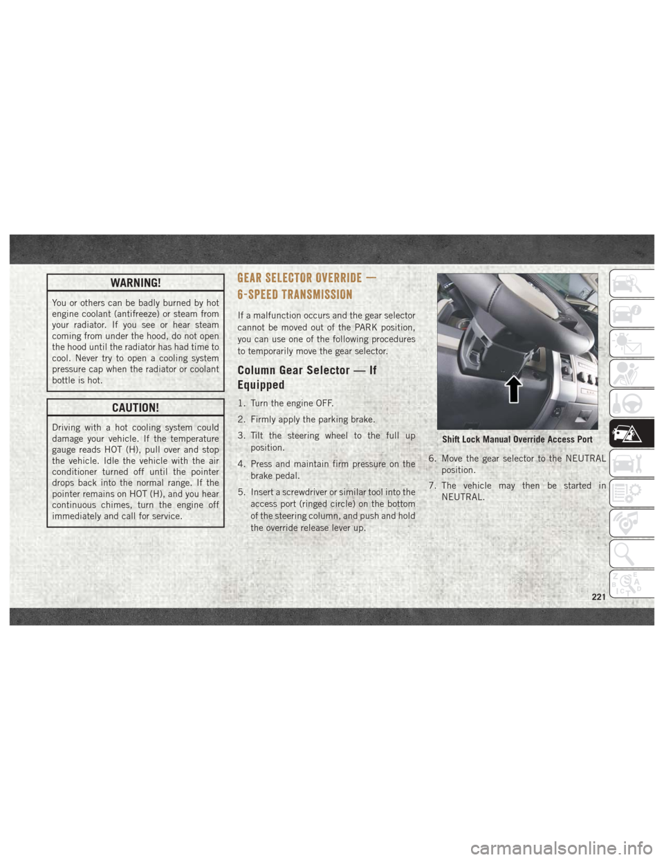
5. Insert a screwdriver or similar tool into the access port (ringed circle) on the bottom
of the steering column, and push and hold
the override release lever up. 6. Move the gear selector to the NEUTRAL
position.
7. The vehicle may then be started in NEUTRAL.
Shift Lock Manual Override Access Port
221
Page 224 of 372

Center Console Gear Selector —
If Equipped
1. Turn the engine OFF.
2. Firmly apply the parking brake.
3. Using a small screwdriver or similar tool,remove the gear selector override access
cover (located to the right of the gear
selector).
4. Press and maintain firm pressure on the brake pedal.
5. Insert the screwdriver or similar tool into the access hole, and push and hold the
override release lever down. 6. Move the gear selector to the NEUTRALposition.
7. The vehicle may then be started in NEUTRAL.
8. Reinstall the gear selector override access cover.
MANUAL PARK RELEASE — 8 SPEED
TRANSMISSION
WARNING!
Always secure your vehicle by fully apply-
ing the parking brake before activating the
Manual Park Release. In addition, you
should be seated in the driver’s seat with
your foot firmly on the brake pedal when
activating the Manual Park Release. Acti-
vating the Manual Park Release will allow
your vehicle to roll away if it is not secured
by the parking brake, or by proper connec-
tion to a tow vehicle. Activating the
Manual Park Release on an unsecured
vehicle could lead to serious injury or
death for those in or around the vehicle.
In order to push or tow the vehicle in cases
where the transmission will not shift out of
PARK (such as a dead battery), a Manual
Park Release is available.
Gear Selector Override Access Cover
IN CASE OF EMERGENCY
222
Page 225 of 372

Follow these steps to activate the Manual
Park Release:
1. Firmly apply the parking brake.
2. Using a small screwdriver or similar tool,remove the Manual Park Release access
cover, which is just above the parking
brake release handle, below and to the left
of the steering column.
3. Press and maintain firm pressure on the brake pedal. 4. Using the screwdriver or similar tool, push
the Manual Park Release lever locking tab
(just below the middle of the lever) to the
right.
5. While holding the locking tab in the disengaged position, pull the tether strap
to rotate the lever rearward, until it locks
in place pointing towards the driver's seat.
Release the locking tab and verify that the
Manual Park Release lever is locked in the
released position. 6. The vehicle is now out of PARK and can be
towed. Release the parking brake only
when the vehicle is securely connected to
a tow vehicle.
To Reset The Manual Park Release:
1. Push the locking tab to the right, to unlock the lever.
Manual Park Release Access Cover
Manual Park Release Lever Locking Tab
Manual Park Release Tether
223
Page 234 of 372
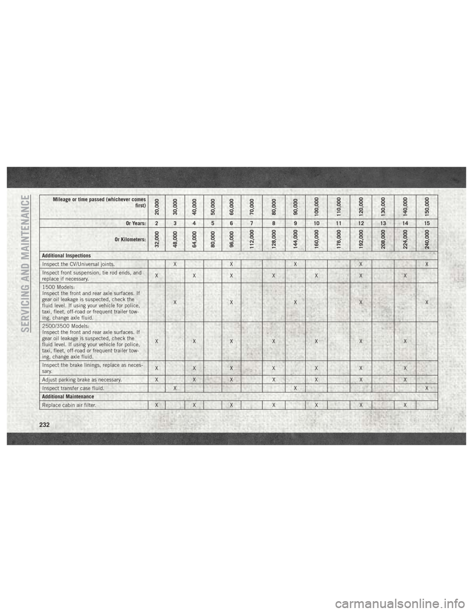
Mileage or time passed (whichever comesfirst)
20,000
30,000
40,000
50,000
60,000
70,000
80,000
90,000
100,000
110,000
120,000
130,000
140,000
150,000
Or Years: 2 3 4 5 6 7 8 9 10 11 12 13 14 15
Or Kilometers:
32,000
48,000
64,000
80,000
96,000
112,000
128,000
144,000
160,000
176,000
192,000
208,000
224,000
240,000
Additional Inspections
Inspect the CV/Universal joints. X X X X X
Inspect front suspension, tie rod ends, and
replace if necessary. XXX X X X X
1500 Models:
Inspect the front and rear axle surfaces. If
gear oil leakage is suspected, check the
fluid level. If using your vehicle for police,
taxi, fleet, off-road or frequent trailer tow-
ing, change axle fluid. XX X X X
2500/3500 Models:
Inspect the front and rear axle surfaces. If
gear oil leakage is suspected, check the
fluid level. If using your vehicle for police,
taxi, fleet, off-road or frequent trailer tow-
ing, change axle fluid. XXX X X X X
Inspect the brake linings, replace as neces-
sary. XXX X X X X
Adjust parking brake as necessary. XXX X X XX
Inspect transfer case fluid. XX X
Additional Maintenance
Replace cabin air filter. XXX X X XX
SERVICING AND MAINTENANCE
232