cooling Ram 3500 2018 User Guide
[x] Cancel search | Manufacturer: RAM, Model Year: 2018, Model line: 3500, Model: Ram 3500 2018Pages: 372, PDF Size: 7.1 MB
Page 49 of 372
sects. Clean with a gentle water spray from
the front of the radiator and through the
condenser.
MAX A/C
MAX A/C sets the control for maximum cool-
ing performance.
Press and release to toggle between MAX A/C
and the prior settings. The button illuminates
when MAX A/C is on.
In MAX A/C, the blower level and mode posi-
tion can be adjusted to desired user settings.
Pressing other settings will cause the MAX
A/C operation to switch to the selected set-
ting and MAX A/C to exit.
Recirculation
When outside air contains smoke, odors, or
high humidity, or if rapid cooling is desired,
you may wish to recirculate interior air by
pressing the Recirculation control button.
The Recirculation indicator will illuminate
when this button is selected. Press the button
a second time to turn off the Recirculation
mode and allow outside air into the vehicle. NOTE:
In cold weather, use of Recirculation mode
may lead to excessive window fogging. The
Recirculation feature may be unavailable
(button on the touchscreen greyed out) if
conditions exist that could create fogging on
the inside of the windshield.
Automatic Temperature Control
(ATC) — If Equipped
Automatic Operation
1. Push the AUTO button on the faceplate,
or the AUTO button on the touchscreen on
the Automatic Temperature Control (ATC)
Panel.
2. Next, adjust the temperature you would like the system to maintain by adjusting
the driver and passenger temperature
control buttons. Once the desired tem-
perature is displayed, the system will
achieve and automatically maintain that
comfort level.
3. When the system is set up for your comfort level, it is not necessary to change the settings. You will experience the greatest
efficiency by simply allowing the system
to function automatically.
NOTE:
• It is not necessary to move the temperature settings for cold or hot vehicles. The system
automatically adjusts the temperature,
mode, and blower speed to provide comfort
as quickly as possible.
• The temperature can be displayed in U.S. or Metric units by selecting the US/Metric
customer-programmable feature. Refer to
the “Uconnect Settings” in “Multimedia”
in your Owner’s Manual for further
information.
To provide you with maximum comfort in the
Automatic mode during cold start-ups, the
blower fan will remain on low until the engine
warms up. The blower will increase in speed
and transition into Auto mode.
47
Page 50 of 372
Manual Operation Override
This system offers a full complement of
manual override features. The AUTO symbol
in the front ATC display will be turned off
when the system is being used in the manual
mode.
Operating Tips
Summer Operation
The engine cooling system must be protected
with a high-quality antifreeze coolant to pro-
vide proper corrosion protection and to pro-
tect against engine overheating. OAT coolant
(conforming to MS.90032) is recommended.
Winter Operation
To ensure the best possible heater and de-
froster performance, make sure the engine
cooling system is functioning properly and
the proper amount, type, and concentration
of coolant is used. Use of the Air Recircula-
tion mode during Winter months is not rec-
ommended, because it may cause window
fogging.
Vacation/Storage
Before you store your vehicle, or keep it out of
service (i.e., vacation) for two weeks or more,
run the air conditioning system at idle for
about five minutes, in fresh air with the
blower setting on high. This will ensure ad-
equate system lubrication to minimize the
possibility of compressor damage when the
system is started again.
Window Fogging
Vehicle windows tend to fog on the inside in
mild, rainy, and/or humid weather. To clear
the windows, select Defrost or Mix mode and
increase the front blower speed. Do not use
the Recirculation mode without A/C for long
periods, as fogging may occur.
Outside Air Intake
Make sure the air intake, located directly in
front of the windshield, is free of obstruc-
tions, such as leaves. Leaves collected in the
air intake may reduce airflow, and if they
enter the plenum, they could plug the water
drains. In Winter months, make sure the air
intake is clear of ice, slush, and snow.
Cabin Air Filter
The climate control system filters out dust
and pollen from the air. Contact an autho-
rized dealer to service your cabin air filter,
and to have it replaced when needed.
GETTING TO KNOW YOUR VEHICLE
48
Page 136 of 372
SAFETY TIPS
Transporting Passengers
NEVER TRANSPORT PASSENGERS IN THE
CARGO AREA.
WARNING!
• Do not leave children or animals insideparked vehicles in hot weather. Interior
heat build-up may cause serious injury
or death.
• It is extremely dangerous to ride in a
cargo area, inside or outside of a vehicle.
In a collision, people riding in these
areas are more likely to be seriously
injured or killed.
• Do not allow people to ride in any area of
your vehicle that is not equipped with
seats and seat belts.
• Be sure everyone in your vehicle is in a
seat and using a seat belt properly.
Exhaust Gas
WARNING!
Exhaust gases can injure or kill. They con-
tain carbon monoxide (CO), which is col-
orless and odorless. Breathing it can make
you unconscious and can eventually poi-
son you. To avoid breathing (CO), follow
these safety tips:
• Do not run the engine in a closed garageor in confined areas any longer than
needed to move your vehicle in or out of
the area.
• If you are required to drive with the
trunk/liftgate/rear doors open, make
sure that all windows are closed and the
climate control BLOWER switch is set at
high speed. DO NOT use the recircula-
tion mode.
• If it is necessary to sit in a parked
vehicle with the engine running, adjust
your heating or cooling controls to force
outside air into the vehicle. Set the
blower at high speed. The best protection against carbon monoxide
entry into the vehicle body is a properly
maintained engine exhaust system.
Whenever a change is noticed in the sound of
the exhaust system, when exhaust fumes can
be detected inside the vehicle, or when the
underside or rear of the vehicle is damaged,
have a competent mechanic inspect the com-
plete exhaust system and adjacent body ar-
eas for broken, damaged, deteriorated, or
mispositioned parts. Open seams or loose
connections could permit exhaust fumes to
seep into the passenger compartment. In
addition, inspect the exhaust system each
time the vehicle is raised for lubrication or oil
change. Replace as required.
Safety Checks You Should Make
Inside The Vehicle
Seat Belts
Inspect the seat belt system periodically,
checking for cuts, frays, and loose parts.
Damaged parts must be replaced immedi-
ately. Do not disassemble or modify the sys-
tem.
SAFETY
134
Page 161 of 372
Only shift from DRIVE to PARK or REVERSE
when the accelerator pedal is released and
the vehicle is stopped. Be sure to keep your
foot on the brake pedal when shifting be-
tween these gears.
The transmission gear selector has only
PARK, REVERSE, NEUTRAL, and DRIVE
shift positions. Manual downshifts can be
made using the Electronic Range Select
(ERS) shift control. Pressing the ERS (-/+)
switches (column shift) or moving the gear
selector to the left or right (-/+) (console shift)
while in the DRIVE position will select the
highest available transmission gear, and will
display that gear limit in the instrument clus-
ter as 1, 2, 3, etc. Refer to "Electronic Range
Select (ERS) Operation" in this section for
further information. Some models will dis-
play both the selected gear limit, and the
actual current gear, while in ERS mode.Transmission Limp Home Mode
Transmission function is monitored electroni-
cally for abnormal conditions. If a condition is
detected that could result in transmission
damage, Transmission Limp Home Mode is
activated. In this mode, the transmission re-
mains in direct gear regardless of which for-
ward gear is selected. PARK, REVERSE, and
NEUTRAL will continue to operate. The Mal-
function Indicator Light (MIL) may be illumi-
nated. Limp Home Mode allows the vehicle to
be driven to an authorized dealer for service
without damaging the transmission.
In the event of a momentary problem, the
transmission can be reset to regain all for-
ward gears by performing the following steps:
1. Stop the vehicle.
2. Shift the transmission into PARK.
3. Turn the ignition OFF.
4. Wait approximately 10 seconds.
5. Restart the engine.
6. Shift into the desired gear range. If theproblem is no longer detected, the trans-
mission will return to normal operation. NOTE:
Even if the transmission can be reset, we
recommend that you visit your authorized
dealer at your earliest possible convenience.
Your authorized dealer has diagnostic equip-
ment to assess the condition of your trans-
mission.
If the transmission cannot be reset, autho-
rized dealer service is required.
Electronic Range Select (ERS) Operation —
Six-Speed Transmission (1500 Models
Only)
The Electronic Range Select (ERS) shift con-
trol allows the driver to limit the highest
available gear when the transmission is in
DRIVE. For example, if you set the transmis-
sion gear limit to 4 (fourth gear), the trans-
mission will not shift above fourth gear, but
will shift through the lower gears normally.
Use of ERS (or TOW/HAUL mode) also en-
ables an additional underdrive gear which is
not normally used during through-gear accel-
erations. This additional gear can improve
vehicle performance and cooling capability
when towing a trailer on certain grades. In
159
Page 221 of 372
NOTE:
The positive battery post may be covered with
a protective cap if equipped. Lift up on the
cap to gain access to the positive battery
post. Do not jump off fuses. Only jump di-
rectly off positive post which has a positive
(+)symbol on or around the post.
WARNING!
• Take care to avoid the radiator cooling
fan whenever the hood is raised. It can
start anytime the ignition switch is ON.
You can be injured by moving fan blades.
• Remove any metal jewelry such as rings,
watch bands and bracelets that could
make an inadvertent electrical contact.
You could be seriously injured.
• Batteries contain sulfuric acid that can
burn your skin or eyes and generate
hydrogen gas which is flammable and
explosive. Keep open flames or sparks
away from the battery.
1. Apply the parking brake, shift the auto- matic transmission into PARK and turn
the ignition to LOCK. 2. Turn off the heater, radio, and all unnec-
essary electrical accessories.
3. If using another vehicle to jump start the battery, park the vehicle within the jumper
cables reach, apply the parking brake and
make sure the ignition is OFF.
WARNING!
Do not allow vehicles to touch each other
as this could establish a ground connec-
tion and personal injury could result.
Jump Starting Procedure
WARNING!
Failure to follow this jump starting proce-
dure could result in personal injury or
property damage due to battery explosion.
CAUTION!
Failure to follow these procedures could
result in damage to the charging system of
the booster vehicle or the discharged ve-
hicle.
Connecting The Jumper Cables
1. Connect the positive (+)end of the jumper
cable to the positive (+)post of the dis-
charged vehicle.
NOTE:
Do not jump off fuses. Only jump directly off
positive post.
2. Connect the opposite end of the positive (+) jumper cable to the positive (+)post of
the booster battery.
3. Connect the negative (-)end of the jumper
cable to the negative (-)post of the
booster battery.
4. Connect the opposite end of the negative (-)jumper cable to a good engine ground
(exposed metal part of the discharged
vehicle’s engine) away from the battery
and the fuel injection system.
WARNING!
Do not connect the jumper cable to the
negative (-) post of the discharged battery.
The resulting electrical spark could cause
the battery to explode and could result in
219
Page 222 of 372
WARNING!
personal injury. Only use the specific
ground point, do not use any other exposed
metal parts.
5. Start the engine in the vehicle that has the booster battery, let the engine idle a
few minutes, and then start the engine in
the vehicle with the discharged battery.
CAUTION!
Do not connect jumper cable to any of the
fuses on the positive battery terminal. The
resulting electrical current will blow the
fuse.
6. Once the engine is started, remove the jumper cables in the reverse sequence:
Disconnecting The Jumper Cables
1. Disconnect the negative (-)end of the
jumper cable from the engine ground of
the vehicle with the discharged battery. 2. Disconnect the opposite end of the nega-
tive (-)jumper cable from the negative (-)
post of the booster battery.
3. Disconnect the positive (+)end of the
jumper cable from the positive (+)post of
the booster battery.
4. Disconnect the opposite end of the posi- tive (+)jumper cable from the positive (+)
post of the vehicle with the discharged
battery.
If frequent jump starting is required to start
your vehicle you should have the battery and
charging system inspected at an authorized
dealer.
CAUTION!
Accessories plugged into the vehicle
power outlets draw power from the vehi-
cle’s battery, even when not in use (i.e.,
cellular devices, etc.). Eventually, if
plugged in long enough without engine
operation, the vehicle’s battery will dis-
charge sufficiently to degrade battery life
and/or prevent the engine from starting.
IF YOUR ENGINE OVERHEATS
In any of the following situations, you can
reduce the potential for overheating by taking
the appropriate action.
• On the highways — slow down.
• In city traffic — while stopped, place the transmission in NEUTRAL, but do not in-
crease the engine idle speed while prevent-
ing vehicle motion with the brakes.
NOTE:
There are steps that you can take to slow
down an impending overheat condition:
• If your air conditioner (A/C) is on, turn it off. The A/C system adds heat to the engine
cooling system and turning the A/C off can
help remove this heat.
• You can also turn the temperature control to maximum heat, the mode control to floor
and the blower control to high. This allows
the heater core to act as a supplement to
the radiator and aids in removing heat from
the engine cooling system.
IN CASE OF EMERGENCY
220
Page 223 of 372
WARNING!
You or others can be badly burned by hot
engine coolant (antifreeze) or steam from
your radiator. If you see or hear steam
coming from under the hood, do not open
the hood until the radiator has had time to
cool. Never try to open a cooling system
pressure cap when the radiator or coolant
bottle is hot.
CAUTION!
Driving with a hot cooling system could
damage your vehicle. If the temperature
gauge reads HOT (H), pull over and stop
the vehicle. Idle the vehicle with the air
conditioner turned off until the pointer
drops back into the normal range. If the
pointer remains on HOT (H), and you hear
continuous chimes, turn the engine off
immediately and call for service.
GEAR SELECTOR OVERRIDE —
6-SPEED TRANSMISSION
If a malfunction occurs and the gear selector
cannot be moved out of the PARK position,
you can use one of the following procedures
to temporarily move the gear selector.
Column Gear Selector — If
Equipped
1. Turn the engine OFF.
2. Firmly apply the parking brake.
3. Tilt the steering wheel to the full upposition.
4. Press and maintain firm pressure on the brake pedal.
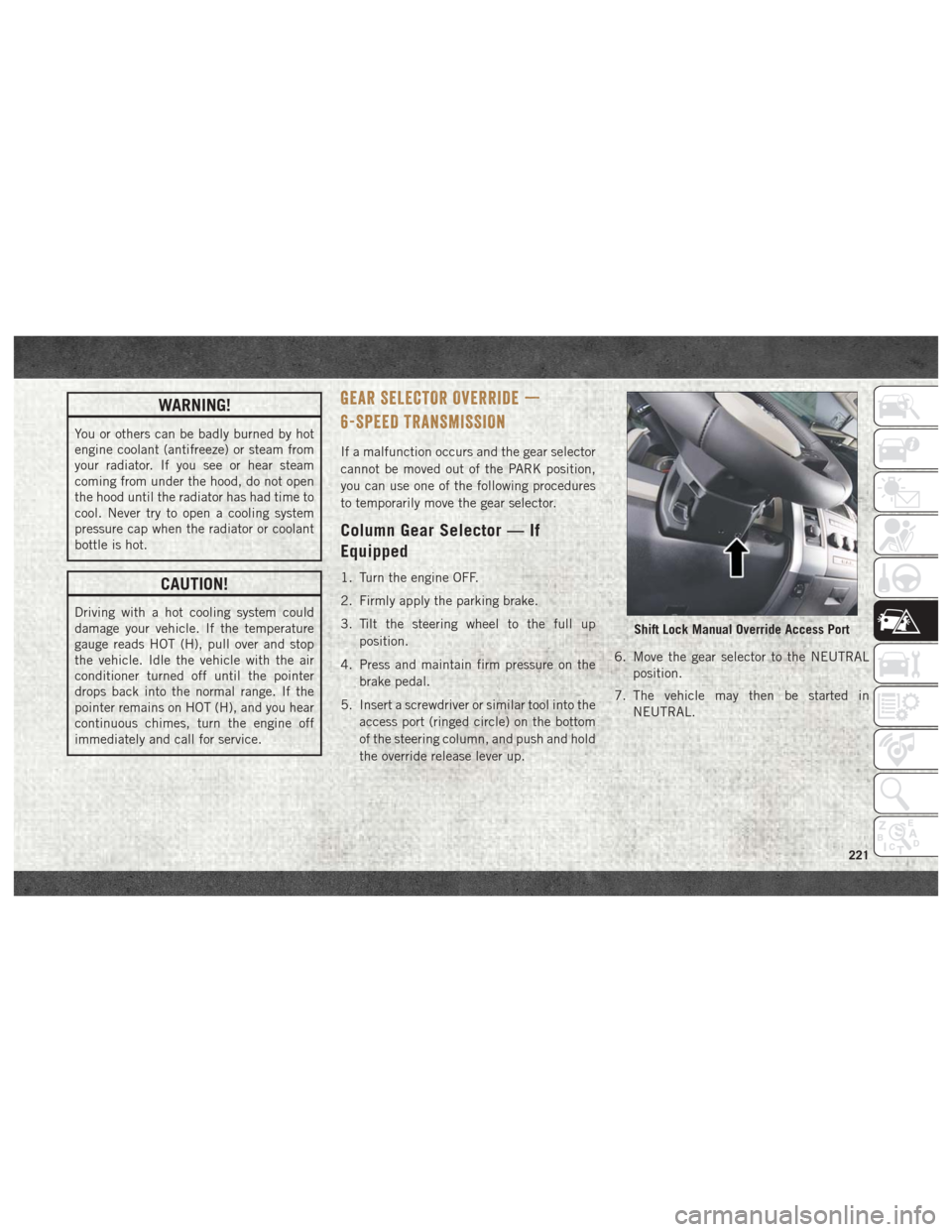
5. Insert a screwdriver or similar tool into the access port (ringed circle) on the bottom
of the steering column, and push and hold
the override release lever up. 6. Move the gear selector to the NEUTRAL
position.
7. The vehicle may then be started in NEUTRAL.
Shift Lock Manual Override Access Port
221
Page 233 of 372
Maintenance Plan — Gasoline
Engine
Required Maintenance
Refer to the Maintenance Plan on the follow-
ing pages for required maintenance.
At Every Oil Change Interval As Indicated By OilChange Indicator System:
• Change oil and filter.
• Rotate the tires. Rotate at the first sign of
irregular wear, even if it occurs before the oil
indicator system turns on.
• Inspect battery and clean and tighten ter- minals as required.
• Inspect automatic transmission fluid if equipped with dipstick.
• Inspect brake pads, shoes, rotors, drums, hoses and park brake.
• Inspect engine cooling system protection and hoses.
• Inspect exhaust system.
• Inspect engine air cleaner if using in dusty or off-road conditions.
• Lube the front drive shaft fitting (2500/ 3500 (4x4) models only).
231
Page 237 of 372

Maintenance Plan — Diesel Fuel
Up To B5 Biodiesel (1500 Diesel)
Required Maintenance
Refer to the Maintenance Schedules on the
following pages for required maintenance.
At Every Oil Change Interval As Indicated By OilChange Indicator System:
• Change oil and filter.
•
Completely fill the Diesel Exhaust Fluid tank.
• Drain water from fuel filter assembly.
• Rotate the tires. Rotate at the first sign of
irregular wear, even if it occurs before the oil
indicator system turns on.
• Inspect battery and clean and tighten ter- minals as required.
• Inspect brake pads, shoes, rotors, drums, hoses and park brake.
• Inspect engine cooling system protection and hoses.
• Inspect exhaust system.
• Inspect engine air cleaner if using in dusty or off-road conditions.
At Every Second Oil Change Interval As Indi-cated By Oil Change Indicator System:
• Change fuel filter.
235
Page 244 of 372

** Under no circumstances should oil
change intervals exceed 15,000 miles
(24 000 km) or six months or 500 Hours,
whichever comes first.
*** The manufacturer highly recommends
that all cooling system service, mainte-
nance, and repairs be performed by your
local authorized dealer.
**** Under no circumstances should the
air cleaner filter element exceed
30,000 miles (48,000 km) or 24 months,
whichever comes first.
WARNING!
• You can be badly injured working on oraround a motor vehicle. Do only service
work for which you have the knowledge
and the right equipment. If you have any
doubt about your ability to perform a
service job, take your vehicle to a com-
petent mechanic.
• Failure to properly inspect and maintain
your vehicle could result in a component
malfunction and effect vehicle handling
WARNING!
and performance. This could cause an
accident.
CAUTION!
***The manufacturer highly recommends
that all cooling system service, mainte-
nance, and repairs be performed by your
local authorized dealer.
SERVICING AND MAINTENANCE
242