display Ram 3500 2019 Owner's Guide
[x] Cancel search | Manufacturer: RAM, Model Year: 2019, Model line: 3500, Model: Ram 3500 2019Pages: 696, PDF Size: 13.89 MB
Page 86 of 696
84 GETTING TO KNOW YOUR VEHICLE
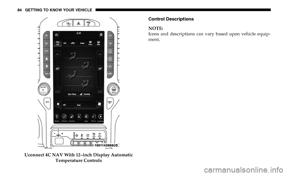
Uconnect 4C NAV With 12–inch Display Automatic Temperature Controls Control Descriptions
NOTE:
Icons and descriptions can vary based upon vehicle equip
-
ment.
Page 89 of 696
GETTING TO KNOW YOUR VEHICLE 87
Driver and Passenger Temperature Up and Down Buttons
Provides the driver and passenger with independent temperature control. Push the red button on the
faceplate or touchscreen or press and slide the temperature bar towards the red arrow button on the
touchscreen for warmer temperature settings. Push the blue button on the faceplate or touchscreen or
press and slide the temperature bar towards the blue arrow button on the touchscreen for cooler
temperature settings.
NOTE:
The numbers within the temperature display will only appear if the system is equipped with an auto-
matic climate control system.
SYNC
Press the SYNC button on the touchscreen to toggle the SYNC feature on/off. The SYNC indicator is
illuminated when this feature is enabled. SYNC is used to synchronize the passenger temperature
setting with the driver temperature setting. Changing the passenger’s temperature setting while in
SYNC will automatically exit this feature.
NOTE:
The SYNC button is only available on the touchscreen.
Icon
Description
2
Page 90 of 696
88 GETTING TO KNOW YOUR VEHICLE
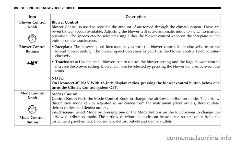
Blower Control Knob
Blower Control Buttons Blower Control
Blower Control is used to regulate the amount of air forced through the climate system. There are
seven blower speeds available. Adjusting the blower will cause automatic mode to switch to manual
operation. The speeds can be selected using either the blower control knob on the faceplate or the
buttons on the touchscreen.
•
Faceplate: The blower speed increases as you turn the blower control knob clockwise from the
lowest blower setting. The blower speed decreases as you turn the blower control knob counter -
clockwise.
• Touchscreen: Use the small blower icon to reduce the blower setting and the large blower icon to
increase the blower setting. Blower can also be selected by pressing the blower bar area between the
icons.
NOTE:
On Uconnect 4C NAV With 12–inch display radios, pressing the blower control button below one
turns the Climate Control system OFF.
Mode Control Knob
Mode Controls Button Modes Control
Control Knob:
Push the Mode Control Knob to change the airflow distribution mode. The airflow
distribution mode can be adjusted so air comes from the instrument panel outlets, floor outlets,
defrost outlets and demist outlets.
Touchscreen: Select Mode by pressing one of the Mode buttons on the touchscreen to change the
airflow distribution mode. The airflow distribution mode can be adjusted so air comes from the
instrument panel outlets, floor outlets, defrost outlets and demist outlets.
Icon
Description
Page 93 of 696

GETTING TO KNOW YOUR VEHICLE 91
Automatic Temperature Control (ATC)
Automatic Operation
1. Push the AUTO button on the faceplate, or the AUTObutton on the touchscreen on the Automatic Temperature
Control (ATC) Panel.
2. Next, adjust the temperature you would like the system to maintain by adjusting the driver and passenger
temperature control buttons. Once the desired tempera -
ture is displayed, the system will achieve and automati -
cally maintain that comfort level.
3. When the system is set up for your comfort level, it is not necessary to change the settings. You will experience the
greatest efficiency by simply allowing the system to func -
tion automatically.
NOTE:
• It is not necessary to move the temperature settings for cold or hot vehicles. The system automatically adjusts the
temperature, mode, and blower speed to provide comfort
as quickly as possible. • The temperature can be displayed in U.S. or Metric units
by selecting the US/Metric customer-programmable
feature. Refer to the “Uconnect Settings” in “Multimedia”
for further information.
To provide you with maximum comfort in the Automatic
mode during cold start-ups, the blower fan will remain on
low until the engine warms up. The blower will increase in
speed and transition into Auto mode.
Manual Operation Override
This system offers a full complement of manual override
features. The AUTO symbol in the front ATC display will be
turned off when the system is being used in the manual
mode.
Operating Tips
NOTE:
Refer to the chart at the end of this section for suggested
control settings for various weather conditions.
2
Page 134 of 696
132 GETTING TO KNOW YOUR VEHICLE
Cargo Camera — If Equipped
Your vehicle may be equipped with the Cargo Camera that
allows you to see an image of the inside of the pickup box.
The image will be displayed in the Uconnect screen.
The Cargo Camera is located in the bottom center area of the
center high-mounted stoplamp (CHMSL).
A touchscreen button to indicate the current active camera
image being displayed is made available whenever the
Cargo Camera image is displayed.
A touchscreen button to switch the display to rear view
camera image is made available whenever the Cargo Camera
image is displayed.
A touchscreen button "X" to disable display of the camera
image is made available when the vehicle is not in REVERSE
gear.
A display timer is initiated when the Cargo Camera image is
displayed. The image will continue to be displayed until the
display timer exceeds 10 seconds and the vehicle speed is
above 8 mph (13 km/h) or the touchscreen button "X" to
disable display of the Cargo Camera image is pressed.NOTE:
• If the vehicle speed remains below 8 mph (13 km/h), the
Cargo Camera image will be displayed continuously until
the touchscreen button "X" to disable display of the Cargo
Camera image is pressed.
• If snow, ice, mud, or any foreign substance builds up on the camera lens, clean the lens, rinse with water, and dry
with a soft cloth. Do not cover the lens.
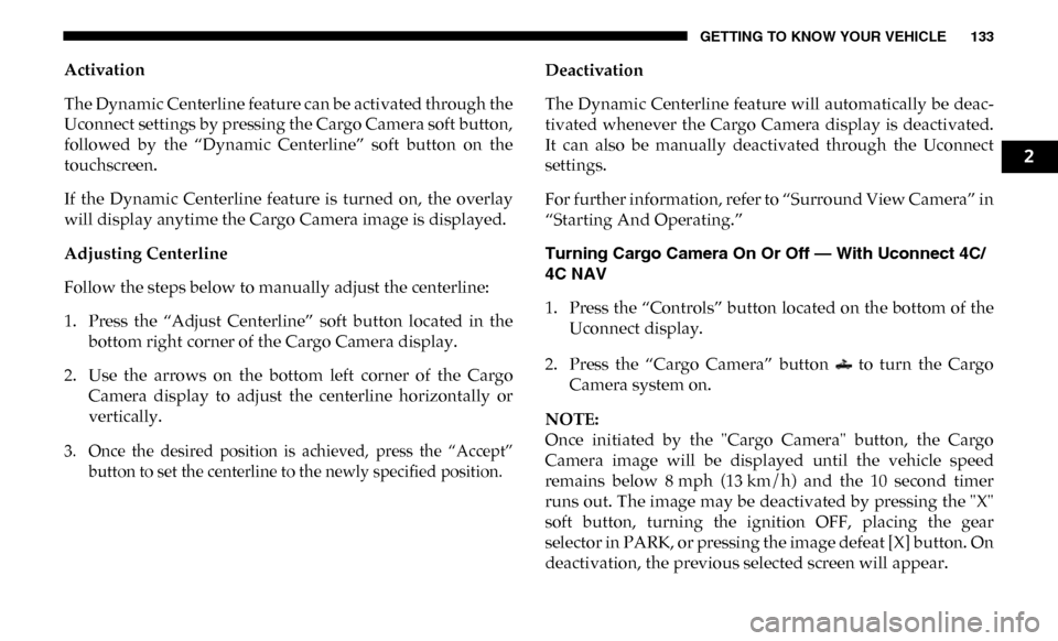
Cargo Camera With Dynamic Centerline (Available With
Surround View Camera Only) — If Equipped
The Dynamic Centerline feature provides an overlay on the
Cargo Camera display screen that aligns to the center of the
pickup box to aid in hooking up a fifth wheel camper or
gooseneck trailer. The centerline auto aligns to the center of
the pickup box, and can also be manually adjusted. The
centerline will adjust in response to steering angle inputs,
and will not obstruct the gooseneck receiver or an
approaching trailer gooseneck in the camera feed.
Page 135 of 696
GETTING TO KNOW YOUR VEHICLE 133
Activation
The Dynamic Centerline feature can be activated through the
Uconnect settings by pressing the Cargo Camera soft button,
followed by the “Dynamic Centerline” soft button on the
touchscreen.
If the Dynamic Centerline feature is turned on, the overlay
will display anytime the Cargo Camera image is displayed.
Adjusting Centerline
Follow the steps below to manually adjust the centerline:
1. Press the “Adjust Centerline” soft button located in thebottom right corner of the Cargo Camera display.
2. Use the arrows on the bottom left corner of the Cargo Camera display to adjust the centerline horizontally or
vertically.
3. Once the desired position is achieved, press the “Accept” button to set the centerline to the newly specified position.
Deactivation
The Dynamic Centerline feature will automatically be deac
-
tivated whenever the Cargo Camera display is deactivated.
It can also be manually deactivated through the Uconnect
settings.
For further information, refer to “Surround View Camera” in
“Starting And Operating.”
Turning Cargo Camera On Or Off — With Uconnect 4C/
4C NAV
1. Press the “Controls” button located on the bottom of the Uconnect display.
2. Press the “Cargo Camera” button to turn the Cargo Camera system on.
NOTE:
Once initiated by the "Cargo Camera" button, the Cargo
Camera image will be displayed until the vehicle speed
remains below 8 mph (13 km/h) and the 10 second timer
runs out. The image may be deactivated by pressing the "X"
soft button, turning the ignition OFF, placing the gear
selector in PARK, or pressing the image defeat [X] button. On
deactivation, the previous selected screen will appear.
2
Page 163 of 696
GETTING TO KNOW YOUR INSTRUMENT PANEL 161
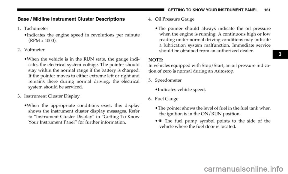
Base / Midline Instrument Cluster Descriptions
1. Tachometer•Indicates the engine speed in revolutions per minute(RPM x 1000).
2. Voltmeter
•When the vehicle is in the RUN state, the gauge indi -
cates the electrical system voltage. The pointer should
stay within the normal range if the battery is charged.
If the pointer moves to either extreme left or right and
remains there during normal driving, the electrical
system should be serviced.
3. Instrument Cluster Display
•When the appropriate conditions exist, this displayshows the instrument cluster display messages. Refer
to “Instrument Cluster Display” in “Getting To Know
Your Instrument Panel” for further information. 4. Oil Pressure Gauge
•The pointer should always indicate the oil pressurewhen the engine is running. A continuous high or low
reading under normal driving conditions may indicate
a lubrication system malfunction. Immediate service
should be obtained from an authorized dealer.
NOTE:
In vehicles equipped with Stop/Start, an oil pressure indica -
tion of zero is normal during an Autostop.
5. Speedometer
•Indicates vehicle speed.
6. Fuel Gauge
•The pointer shows the level of fuel in the fuel tank whenthe ignition is in the ON/RUN position.
• The fuel pump symbol points to the side of the vehicle where the fuel door is located.
3
Page 166 of 696
164 GETTING TO KNOW YOUR INSTRUMENT PANEL
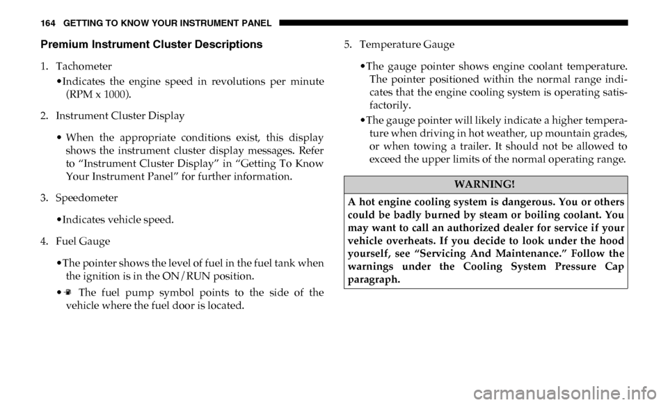
Premium Instrument Cluster Descriptions
1. Tachometer•Indicates the engine speed in revolutions per minute(RPM x 1000).
2. Instrument Cluster Display
• When the appropriate conditions exist, this displayshows the instrument cluster display messages. Refer
to “Instrument Cluster Display” in “Getting To Know
Your Instrument Panel” for further information.
3. Speedometer
•Indicates vehicle speed.
4. Fuel Gauge
•The pointer shows the level of fuel in the fuel tank whenthe ignition is in the ON/RUN position.
• The fuel pump symbol points to the side of the vehicle where the fuel door is located. 5. Temperature Gauge
•The gauge pointer shows engine coolant temperature.The pointer positioned within the normal range indi -
cates that the engine cooling system is operating satis -
factorily.
•The gauge pointer will likely indicate a higher tempera -
ture when driving in hot weather, up mountain grades,
or when towing a trailer. It should not be allowed to
exceed the upper limits of the normal operating range.
WARNING!
A hot engine cooling system is dangerous. You or others
could be badly burned by steam or boiling coolant. You
may want to call an authorized dealer for service if your
vehicle overheats. If you decide to look under the hood
yourself, see “Servicing And Maintenance.” Follow the
warnings under the Cooling System Pressure Cap
paragraph.
Page 167 of 696
GETTING TO KNOW YOUR INSTRUMENT PANEL 165
INSTRUMENT CLUSTER DISPLAY
Your vehicle will be equipped with an instrument cluster
display, which offers useful information to the driver. With
the ignition in the STOP/OFF mode, opening/closing of a
door will activate the display for viewing, and display the
total miles, or kilometers, in the odometer. Your instrument
cluster display is designed to display important information
about your vehicle’s systems and features. Using a driver
interactive display located on the instrument panel, your
instrument cluster display can show you how systems are
working and give you warnings when they are not. The
steering wheel mounted controls allow you to scroll through
the main menus and submenus. You can access the specific
information you want and make selections and adjustments.
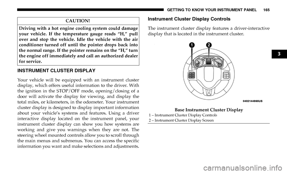
Instrument Cluster Display Controls
The instrument cluster display features a driver-interactive
display that is located in the instrument cluster.Base Instrument Cluster Display
CAUTION!
Driving with a hot engine cooling system could damage
your vehicle. If the temperature gauge reads “H,” pull
over and stop the vehicle. Idle the vehicle with the air
conditioner turned off until the pointer drops back into
the normal range. If the pointer remains on the “H,” turn
the engine off immediately and call an authorized dealer
for service.
1 – Instrument Cluster Display Controls
2 – Instrument Cluster Display Screen
3
Page 168 of 696
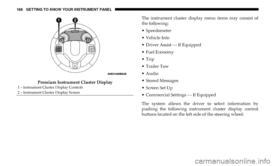
166 GETTING TO KNOW YOUR INSTRUMENT PANEL
Premium Instrument Cluster DisplayThe instrument cluster display menu items may consist of
the following:
• Speedometer
• Vehicle Info
• Driver Assist — If Equipped
• Fuel Economy
• Trip
• Trailer Tow
• Audio
• Stored Messages
• Screen Set Up
• Commercial Settings — If Equipped
The system allows the driver to select information by
pushing the following instrument cluster display control
buttons located on the left side of the steering wheel:
1 – Instrument Cluster Display Controls
2 – Instrument Cluster Display Screen