Anc module Ram 3500 2019 Owner's Manual
[x] Cancel search | Manufacturer: RAM, Model Year: 2019, Model line: 3500, Model: Ram 3500 2019Pages: 696, PDF Size: 13.89 MB
Page 224 of 696

222 SAFETY
• The TPMS is not a substitute for proper tire maintenance,and it is the driver’s responsibility to maintain correct tire
pressure using an accurate tire pressure gauge, even if
under-inflation has not reached the level to trigger illumi -
nation of the TPMS Warning Light.
• Seasonal temperature changes will affect tire pressure, and the TPMS will monitor the actual tire pressure in the tire.
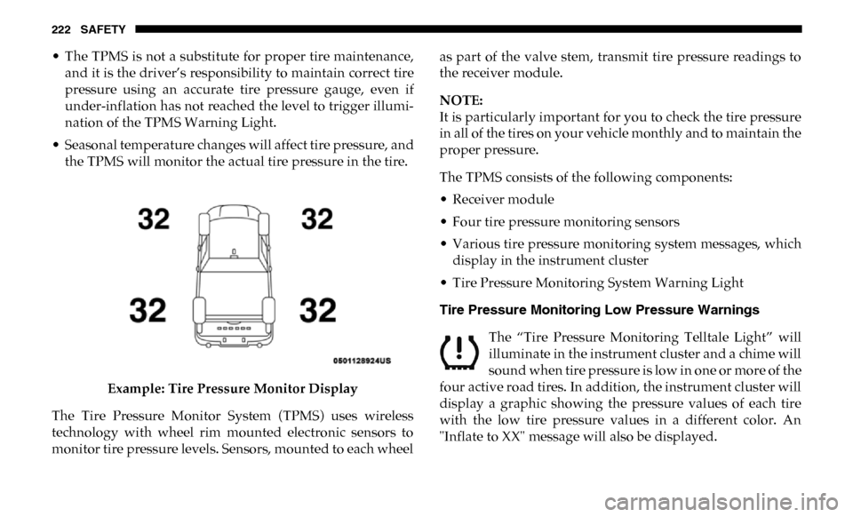
Example: Tire Pressure Monitor Display
The Tire Pressure Monitor System (TPMS) uses wireless
technology with wheel rim mounted electronic sensors to
monitor tire pressure levels. Sensors, mounted to each wheel as part of the valve stem, transmit tire pressure readings to
the receiver module.
NOTE:
It is particularly important for you to check the tire pressure
in all of the tires on your vehicle monthly and to maintain the
proper pressure.
The TPMS consists of the following components:
• Receiver module
• Four tire pressure monitoring sensors
• Various tire pressure monitoring system messages, which
display in the instrument cluster
• Tire Pressure Monitoring System Warning Light
Tire Pressure Monitoring Low Pressure Warnings
The “Tire Pressure Monitoring Telltale Light” will
illuminate in the instrument cluster and a chime will
sound when tire pressure is low in one or more of the
four active road tires. In addition, the instrument cluster will
display a graphic showing the pressure values of each tire
with the low tire pressure values in a different color. An
"Inflate to XX" message will also be displayed.
Page 373 of 696

STARTING AND OPERATING 371
The “ACC/FCW Limited Functionality Clean Front Wind-
shield” message can sometimes be displayed while driving
in adverse weather conditions. The ACC/FCW system will
recover after the vehicle has left these areas. Under rare
conditions, when the camera is not tracking any vehicles or
objects in its path this warning may temporarily occur.
If weather conditions are not a factor, the driver should
examine the windshield and the camera located on the back
side of the inside rear view mirror. They may require
cleaning or removal of an obstruction.
When the condition that created limited functionality is no
longer present, the system will return to full functionality.
NOTE:
If the “ACC/FCW Limited Functionality Clean Front Wind -
shield” message occurs frequently (e.g. more than once on
every trip) without any snow, rain, mud, or other obstruc -
tion, have the windshield and forward facing camera
inspected at your authorized dealer. Service ACC/FCW Warning
If the system turns off, and the instrument cluster displays
“ACC/FCW Unavailable Service Required” or “Cruise/
FCW Unavailable Service Required”, there may be an
internal system fault or a temporary malfunction that limits
ACC functionality. Although the vehicle is still drivable
under normal conditions, ACC will be temporarily unavail
-
able. If this occurs, try activating ACC again later, following
an ignition cycle. If the problem persists, see your authorized
dealer.
Precautions While Driving With ACC
In certain driving situations, ACC may have detection issues.
In these cases, ACC may brake late or unexpectedly. The
driver needs to stay alert and may need to intervene.
NOTE:
• Aftermarket add-ons such as snow plows, lift kits, and brush/grille bars can hinder module performance. Ensure
the radar/camera has no obstructions in the field of view.
• Height modifications can limit module performance and functionality.
5
Page 374 of 696

372 STARTING AND OPERATING
• Do not put stickers or easy passes over the camera/radarfield of view.
• Any modifications to the vehicle that may obstruct the field of view of the radar/camera are not recommended.
Cleaning Instructions
Dust and dirt can accumulate on the cover and block the
camera lens. Clean the camera lens with a soft microfiber
cloth, being careful not to damage or scratch the module.
Towing A Trailer
ACC while towing a trailer is recommended only with an
Integrated Trailer Brake Controller. Aftermarket trailer
brake controllers will not activate the trailer brakes when
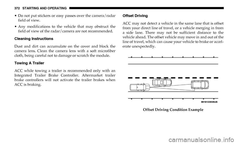
ACC is braking. Offset Driving
ACC may not detect a vehicle in the same lane that is offset
from your direct line of travel, or a vehicle merging in from
a side lane. There may not be sufficient distance to the
vehicle ahead. The offset vehicle may move in and out of the
line of travel, which can cause your vehicle to brake or accel
-
erate unexpectedly.
Offset Driving Condition Example
Page 423 of 696

STARTING AND OPERATING 421
Integrated Trailer Brake Module — If Equipped
Your vehicle may have an Integrated Trailer Brake Module
(ITBM) for Electric and Electric Over Hydraulic (EOH) trailer
brakes.
NOTE:
This module has been designed and verified with electric
trailer brakes and new electric over hydraulic systems. Some
previous EOH systems may not be compatible with ITBM.Integrated Trailer Brake Module (ITBM)
The user interface consists of the following:
Manual Brake Control Lever
Slide the manual brake control lever to the left to activate
power to the trailer's electric brakes independent of the tow
vehicle's brakes. If the manual brake control lever is acti -
vated while the brake is also applied, the greater of the two
inputs determines the power sent to the trailer brakes.
CAUTION!
If the trailer weighs more than 1,000 lbs (453 kg) loaded,
it should have its own brakes and they should be of
adequate capacity. Failure to do this could lead to
accelerated brake lining wear, higher brake pedal effort,
and longer stopping distances.
1 — GAIN Adjustment Button
2 — GAIN Adjustment Button
3 — Manual Brake Control Lever
5
Page 426 of 696

424 STARTING AND OPERATING
Display Messages
The trailer brake control interacts with the instrument cluster
display. Display messages, along with a single chime, will be
displayed when a malfunction is determined in the trailer
connection, trailer brake control, or on the trailer. Refer to
“Instrument Cluster Display” in “Getting To Know Your
Instrument Panel” for further information.NOTE:
• An aftermarket controller may be available for use with
trailers with air or electric-over-hydraulic trailer brake
systems. To determine the type of brakes on your trailer
and the availability of controllers, check with your trailer
manufacturer or dealer.
• Removal of the ITBM will cause errors and it may cause damage to the electrical system and electronic modules of
the vehicle. See your authorized dealer if an aftermarket
module is to be installed.
Towing Requirements — Trailer Lights And Wiring
Whenever you pull a trailer, regardless of the trailer size,
stoplights and turn signals on the trailer are required for
motoring safety.
The Trailer Tow Package may include a four- and seven-pin
wiring harness. Use a factory approved trailer harness and
connector.
NOTE:
Do not cut or splice wiring into the vehicle’s wiring harness.
The electrical connections are all complete to the vehicle but
you must mate the harness to a trailer connector. Refer to the
following illustrations.
WARNING!
Connecting a trailer that is not compatible with the
ITBM system may result in reduced or complete loss of
trailer braking. There may be a increase in stopping
distance or trailer instability which could result in
personal injury.
CAUTION!
Connecting a trailer that is not compatible with the
ITBM system may result in reduced or complete loss of
trailer braking. There may be a increase in stopping
distance or trailer instability which could result in
damage to your vehicle, trailer, or other property.
Page 466 of 696

464 IN CASE OF EMERGENCY
F67–10 Amp Red CD / DVD / UCI Port – If Equipped (HD Only)
Bluetooth Hands-Free Module / CD – If
Equipped (DS 1500 Only)
F68 –10 Amp Red AEB RACAM HTR – If Equipped (HD Only)
F69 –15 Amp Blue SCR Module – If Equipped (HD Only)
F70 –30 Amp Green Fuel Pump Motor / K09 RLY Coil Feed
(Cummins Diesel) – If Equipped
F71 –25 Amp Clear Amplifier / Active Noise Cancelation – If
Equipped (HD Only)
F72 –10 Amp Red PCM / DC/DC Converter Voltage– If Equipped
(DS 1500 Only)
F73 –20 Amp Yellow Fuel Transfer Pump (Rear Tank) – If Equipped
(HD Only)
F74 –20 Amp Yellow Brake Vacuum Pump Gas/Diesel – If Equipped
(DS 1500 Only)
F74 –10 Amp Red Backup Alarm – If Equipped (HD Only)
F75 –10 Amp Red ATMM / Coil-SCR Module RLY– If Equipped
(HD Only)
Coolant Temperature Valve – If Equipped (DS
1500 Only)
Cavity
Cartridge Fuse Micro Fuse Description
Page 467 of 696

IN CASE OF EMERGENCY 465
F76–10 Amp Red Electronic Stability Control (HD Only)
Brake System Module / Stop Lamp Switch /
Electric Park Brake / Clutch Pedal Switch (DS
1500 Only)
F77 –10 Amp Red Drivetrain Control Module / Front Axle
Disconnect Module / TCM (HD Only)
Drivetrain Control Module / ELSD / Front Axle
Disconnect Module / Transmission Control
Relay / RDM / Power Take Off Unit – If
Equipped (DS 1500 Only)
F78 –10 Amp Red Engine Control Module / Powertrain Control
Module / Electric Power Steering (DS 1500
Only)
F78 –15 Amp Blue Engine Control Module / Powertrain Control
Module / AEB RACM MOD / Feed To AUX
PDC Relay Coils (HD Only)
F79 –15 Amp Blue ID / Clearance Lights
F80 –10 Amp Red Universal Garage Door Opener / Compass /
Anti-Intrusion Module (DS 1500 Only)
ASSY Overhead Console / SW Assist / SW 911
– If Equipped (HD Only)
F81 –20 Amp Yellow Trailer Tow Right Turn / Stop Lights - If
Equipped
Cavity
Cartridge Fuse Micro Fuse Description
6
Page 594 of 696

592 MULTIMEDIA
Compass Settings — If Equipped
After pressing the “Compass Settings” button on the touchscreen, the following settings will be available:Setting Name Selectable Options
Variance 1 2 3 4 5 6 7 8 9 10 11 12 13 14 15
NOTE:
• Compass Variance is the difference between Magnetic North and Geographic North. To compensate for the differences the variance should be set for the zone where the vehicle is driven, per the zone map. Once properly set, the compass will auto -
matically compensate for the differences, and provide the most accurate compass heading.
• Keep magnetic materials away from the top of the instrument panel, such as iPod's, Mobile Phones, Laptops and Radar Detectors. This is where the compass module is located, and it can cause interference with the compass sensor, and it may
give false readings.
Perform Compass Calibration On
Off
NOTE:
Press the “Calibration” button on the touchscreen to change this setting. This compass is self-calibrating, which eliminates
the need to manually reset the compass. When the vehicle is new, the compass may appear erratic until it is calibrated. You
may also calibrate the compass by pressing the “ON” button on the touchscreen and completing one or more 360-degree
turns (in an area free from large metal or metallic objects). The compass will now function normally.