Oil change Ram 3500 2020 Owner's Manual
[x] Cancel search | Manufacturer: RAM, Model Year: 2020, Model line: 3500, Model: Ram 3500 2020Pages: 568
Page 10 of 568

8
BULB REPLACEMENT ....................................... 351 Replacement Bulbs ..................................351Replacing Exterior Bulbs ...........................353
FUSES .................................................................. 358
Power Distribution Center .........................358
JACKING AND TIRE CHANGING ...................... 365
Jack Location .............................................365Removal Of Jack And Tools .......................365
Removing The Spare Tire ..........................367
Preparations For Jacking...........................368
Jacking Instructions ...................................368
To Stow The Flat Or Spare ........................ 372Reinstalling The Jack And Tools ...............373
Hub Caps/Wheel Covers — If Equipped ...374
JUMP STARTING ................................................ 375
Preparations For Jump Start .....................375Jump Starting Procedure...........................376
GEAR SELECTOR OVERRIDE — 6–SPEED
TRANSMISSION ................................................ 377
MANUAL PARK RELEASE — 8 – SPEED
TRANSMISSION ................................................ 378
IF YOUR ENGINE OVERHEATS ......................... 379
FREEING A STUCK VEHICLE ............................ 380 TOWING A DISABLED VEHICLE .......................381
Two-Wheel Drive Models ........................... 382
Four-Wheel Drive Models .......................... 383Emergency Tow Hooks — If Equipped ...... 384
ENHANCED ACCIDENT RESPONSE
SYSTEM (EARS) ................................................. 384
EVENT DATA RECORDER (EDR) .......................384
SERVICING AND MAINTENANCE
SCHEDULED SERVICING — GAS ENGINE .......385
Maintenance Plan — Gasoline Engine...... 386
Heavy Duty Use Of The Vehicle................. 389
SCHEDULED SERVICING— DIESEL ENGINE .... 389
Oil Change Indicator System —
Cummins Diesel......................................... 390 Perform Service Indicator —
Cummins Diesel ........................................ 390 Maintenance Plan — Cummins Diesel
Engine ........................................................ 391
ENGINE COMPARTMENT .................................. 396
6.4L Engine ................................................ 396
6.7L Diesel Engine — Six-Speed 68RFE ... 397
6.7L Diesel Engine — Six-Speed AISIN
(AS69RC HD) .............................................. 398 Checking Oil Level — Gas Engine ............. 399
Checking Oil Level — Diesel Engine .......... 399
Adding Washer Fluid ................................. 399Maintenance-Free Battery ....................... 400Pressure Washing...................................... 400
DEALER SERVICE .............................................. 401
Engine Oil .................................................. 401
Engine Oil Filter ......................................... 403Engine Air Cleaner Filter ........................... 403
Air Conditioner Maintenance ................... 405
Accessory Drive Belt Inspection ............... 408Draining Fuel/Water Separator Filter —
Diesel Engine ............................................ 409 Engine Mounted Fuel Filter
Replacement — Diesel Engine .................. 410 Underbody Mounted Fuel Filter
Replacement — Diesel Engine .................. 412 Priming If The Engine Has Run Out Of
Fuel — Diesel Engine ................................. 412 Intervention Regeneration Strategy —
Message Process Flow ............................. 413 Diesel Exhaust Fluid .................................. 414
Body Lubrication ........................................ 414
20_DJD2_OM_EN_USC_t.book Page 8
Page 117 of 568
GETTING TO KNOW YOUR INSTRUMENT PANEL115
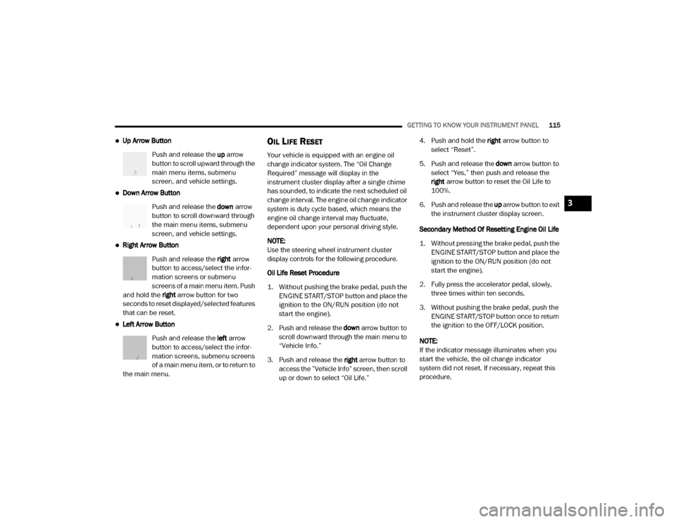
Up Arrow Button
Push and release the up arrow
button to scroll upward through the
main menu items, submenu
screen, and vehicle settings.
Down Arrow Button
Push and release the down arrow
button to scroll downward through
the main menu items, submenu
screen, and vehicle settings.
Right Arrow Button
Push and release the right arrow
button to access/select the infor -
mation screens or submenu
screens of a main menu item. Push
and hold the right arrow button for two
seconds to reset displayed/selected features
that can be reset.
Left Arrow Button
Push and release the left arrow
button to access/select the infor -
mation screens, submenu screens
of a main menu item, or to return to
the main menu.
OIL LIFE RESET
Your vehicle is equipped with an engine oil
change indicator system. The “Oil Change
Required” message will display in the
instrument cluster display after a single chime
has sounded, to indicate the next scheduled oil
change interval. The engine oil change indicator
system is duty cycle based, which means the
engine oil change interval may fluctuate,
dependent upon your personal driving style.
NOTE:
Use the steering wheel instrument cluster
display controls for the following procedure.
Oil Life Reset Procedure
1. Without pushing the brake pedal, push the ENGINE START/STOP button and place the
ignition to the ON/RUN position (do not
start the engine).
2. Push and release the down arrow button to
scroll downward through the main menu to
“Vehicle Info.”
3. Push and release the right arrow button to
access the ”Vehicle Info” screen, then scroll
up or down to select “Oil Life.” 4. Push and hold the
right arrow button to
select “Reset”.
5. Push and release the down arrow button to
select “Yes,” then push and release the
right arrow button to reset the Oil Life to
100%.
6. Push and release the up arrow button to exit
the instrument cluster display screen.
Secondary Method Of Resetting Engine Oil Life
1. Without pressing the brake pedal, push the ENGINE START/STOP button and place the
ignition to the ON/RUN position (do not
start the engine).
2. Fully press the accelerator pedal, slowly, three times within ten seconds.
3. Without pushing the brake pedal, push the ENGINE START/STOP button once to return
the ignition to the OFF/LOCK position.
NOTE:
If the indicator message illuminates when you
start the vehicle, the oil change indicator
system did not reset. If necessary, repeat this
procedure.
3
20_DJD2_OM_EN_USC_t.book Page 115
Page 118 of 568
116GETTING TO KNOW YOUR INSTRUMENT PANEL
DISPLAY MENU ITEMS
Push and release the up or down arrow button
until the desired selectable menu icon is
highlighted in the instrument cluster display.
Refer to “Instrument Cluster Display” in this
chapter for further information.
Speedometer
Push and release the up or down arrow button
until the speedometer menu item is highlighted
in the instrument cluster display. Push and
release the right arrow button to cycle the
display between mph and km/h.
Vehicle Info
Push and release the up or down arrow button
until the Vehicle Info menu item is highlighted in
the instrument cluster display. Push and
release the right arrow button to enter the
submenus items of Vehicle Info. Follow the
directional prompts to access or reset any of the
following Vehicle Info submenu items:
Tire Pressure
Coolant Temperature
Transmission Temperature — If Equipped
Oil Temperature
Oil Pressure
Exhaust Brake — If Equipped
Turbo Boost — If Equipped
Oil Life
Fuel Filter Life — If Equipped
Battery Voltage
Gauge Summary
Engine Hours
Driver Assist — If Equipped
The Driver Assist menu displays the status of
the Adaptive Cruise Control (ACC) and
LaneSense systems.
Push and release the up or down arrow button
until the Driver Assist menu is displayed in the
instrument cluster display.
Adaptive Cruise Control (ACC) Feature
The instrument cluster display displays the
current ACC system settings. The information
displayed depends on ACC system status. Push the Adaptive Cruise Control (ACC) on/off
button (located on the steering wheel) until one
of the following displays in the instrument
cluster display:
Adaptive Cruise Control Off
When ACC is deactivated, the display will read
“Adaptive Cruise Control Off.”
Adaptive Cruise Control Ready
When ACC is activated but the vehicle speed
setting has not been selected, the display will
read “Adaptive Cruise Control Ready.”
Push the SET + or the SET- button (located on
the steering wheel) and the following will display
in the instrument cluster display:
ACC SET
When ACC is set, the set speed will display in
the instrument cluster.
The ACC screen may display once again if any
ACC activity occurs, which may include any of
the following:
Distance Setting Change
System Cancel
Driver Override
20_DJD2_OM_EN_USC_t.book Page 116
Page 120 of 568
118GETTING TO KNOW YOUR INSTRUMENT PANEL
Stored Messages
Push and release the up or down arrow button
until the Messages Menu item is highlighted.
This feature shows the number of stored
warning messages. Push and release the right
or left arrow buttons to cycle through stored
messages.
Screen Setup Menu Item
Push and release the up or down arrow button
until the Screen Setup menu item is highlighted
in the instrument cluster display. Push and
release the right arrow button to enter the
Screen Setup submenu. The Screen Setup
feature allows you to change what information
is displayed in the instrument cluster as well as
the location that information is displayed.
Current Gear — If Equipped
Off (Default Setting)
On
Odometer
Unit Without Decimal (Default Setting)
Unit With Decimal Favorite Menu
Speedometer
Vehicle Info
Driver Assist (Show/Hide) — If Equipped
Fuel Economy (Show/Hide)
Trip Info (Show/Hide)
Trailer Tow (Show/Hide) — If Equipped
Audio (Show/Hide)
Messages
Screen Setup
Commercial Settings — If Equipped
NOTE:
Menus with (Show/Hide) can push the Right
arrow button to choose whether to show or hide
this menu in the instrument cluster display.
Upper Left
None
Compass (Default Setting) — If Equipped
Outside Temp — If Equipped
Time
Range To Empty
Average MPG
Current MPG
Trip A Distance
Trip B Distance
Trailer Trip — If Equipped
Trailer Brake — If Equipped
Oil Pressure — If Equipped
Coolant Temperature — If Equipped
Oil Temperature — If Equipped
Battery Voltage — If Equipped
Transmission Temperature — If Equipped
Oil Life — If Equipped
Exhaust Brake — If Equipped
Turbo Boost — If Equipped
Fuel Filter Life — If Equipped
20_DJD2_OM_EN_USC_t.book Page 118
Page 128 of 568

126GETTING TO KNOW YOUR INSTRUMENT PANEL
remove the trapped Particulate Matter (PM).
If this occurs, the “Exhaust Filter XX% Full
Safely Drive at Highway Speeds to Remedy”
message will be displayed in the instrument
cluster display. If this message is displayed,
you will hear one chime to assist in alerting
you of this condition
By simply driving your vehicle at highway
speeds for as little as 45 minutes, you can
remedy the condition in the particulate filter
system and allow your Cummins diesel
engine and exhaust after-treatment system
to remove the trapped Particulate Matter
(PM) and restore the system to normal oper-
ating condition.
Exhaust System — Regeneration In Process
Exhaust Filter XX% Full — Indicates that the
Diesel Particulate Filter (DPF) is self-cleaning.
Maintain your current driving condition until
regeneration is completed.
Exhaust System — Regeneration Completed
— This message indicates that the Diesel
Particulate Filter (DPF) self-cleaning is
completed. If this message is displayed, you
will hear one chime to assist in alerting you of
this condition.
Exhaust Service Required — See Dealer Now
— This message indicates regeneration has
been disabled due to a system malfunction.
At this point the engine Powertrain Control
Module (PCM) will register a fault code, the
instrument panel will display a MIL light.
Exhaust Filter Full — Power Reduced See
Dealer — This message indicates the PCM
has derated the engine to limit the likelihood
of permanent damage to the after-treatment
system. If this condition is not corrected and
a dealer service is not performed, extensive
exhaust after-treatment damage can occur.
To correct this condition it will be necessary
to have your vehicle serviced by your local
authorized dealer.
NOTE:
Failing to follow the oil change indicator,
changing your oil and resetting the oil change
indicator by 0 miles remaining will prevent the
diesel exhaust filter from performing it's cleaning routine. This will shortly result in a
Malfunction Indicator Light (MIL) and reduced
engine power. Only an authorized dealer will be
able to correct this condition.
Cold Ambient Derate Mode Messages
The vehicle will display messages when a
derate (engine power reduction) is activated to
protect the engine during start up in cold
ambient temperatures.
Engine Power Reduced During Warmup
—
This message will display during start up
when the ambient temperature is between
10°F (-12°C) and -10°F (-23°C).
Engine Power Reduced Up To 30 Sec
(Seconds) During Warmup — This message
will display during start up when the ambient
temperature is between -10°F (-23°C) and
-25°F (-32°C).
CAUTION!
See an authorized dealer, as damage to the
exhaust system could occur soon with
continued operation.
CAUTION!
See an authorized dealer, as damage to the
exhaust system could occur soon with
continued operation.
20_DJD2_OM_EN_USC_t.book Page 126
Page 212 of 568
210SAFETY
The best protection against carbon monoxide
entry into the vehicle body is a properly
maintained engine exhaust system.
Whenever a change is noticed in the sound of
the exhaust system, when exhaust fumes can
be detected inside the vehicle, or when the
underside or rear of the vehicle is damaged,
have a competent mechanic inspect the
complete exhaust system and adjacent body
areas for broken, damaged, deteriorated, or
mispositioned parts. Open seams or loose
connections could permit exhaust fumes to
seep into the passenger compartment. In
addition, inspect the exhaust system each time
the vehicle is raised for lubrication or oil
change. Replace as required.
SAFETY CHECKS YOU SHOULD MAKE
I
NSIDE THE VEHICLE
Seat Belts
Inspect the seat belt system periodically,
checking for cuts, frays, and loose parts.
Damaged parts must be replaced immediately.
Do not disassemble or modify the system.
Front seat belt assemblies must be replaced
after a collision. Rear seat belt assemblies must
be replaced after a collision if they have been
damaged (i.e., bent retractor, torn webbing,
etc.). If there is any question regarding seat belt
or retractor condition, replace the seat belt.
Air Bag Warning Light
The Air Bag warning light will turn on for four
to eight seconds as a bulb check when the
ignition switch is first turned to ON/RUN. If the
light is either not on during starting, stays on, or
turns on while driving, have the system
inspected at an authorized dealer as soon as
possible. After the bulb check, this light will
illuminate with a single chime when a fault with the Air Bag System has been detected. It will
stay on until the fault is removed. If the light
comes on intermittently or remains on while
driving, have an authorized dealer service the
vehicle immediately.
Refer to “Occupant Restraint Systems” in
“Safety” for further information.
Defroster
Check operation by selecting the defrost mode
and place the blower control on high speed. You
should be able to feel the air directed against
the windshield. See an authorized dealer for
service if your defroster is inoperable.
Floor Mat Safety Information
Always use floor mats designed to fit your
vehicle. Only use a floor mat that does not
interfere with the operation of the accelerator,
brake or clutch pedals. Only use a floor mat that
is securely attached using the floor mat
fasteners so it cannot slip out of position and
interfere with the accelerator, brake or clutch
pedals or impair safe operation of your vehicle
in other ways.
If it is necessary to sit in a parked vehicle
with the engine running, adjust your
heating or cooling controls to force outside
air into the vehicle. Set the blower at high
speed.
WARNING!
(Continued)
20_DJD2_OM_EN_USC_t.book Page 210
Page 228 of 568

226STARTING AND OPERATING
NOTE:
If ambient temperatures are low and the coolant
temperature is below 180°F (82°C), the engine
idle speed will slowly increase to 1,000 RPM after
two minutes of idle, if the following conditions are
met:
Foot is off brake pedal and throttle pedal.
Automatic transmission is in PARK.
Vehicle speed is 0 mph (0 km/h).
Applying the throttle will cancel fast idle.
Operating the exhaust brake at idle will
greatly improve warm up rate and will help
keep the engine close to operating tempera -
ture during extended idle.
ENGINE IDLING
Avoid prolonged idling, long periods of idling
may be harmful to your engine because
combustion chamber temperatures can drop so
low that the fuel may not burn completely.
Incomplete combustion allows carbon and
varnish to form on piston rings, engine valves,
and injector nozzles. Also, the unburned fuel
can enter the crankcase, diluting the oil and
causing rapid wear to the engine. If the engine is allowed to idle or the truck is
driven on low engine speed drive cycles for
more than 2 hours, the system will
automatically enter an emissions operating
mode that will increase the engine idle speed to
900 RPM. While in this mode, which is designed
to help maintain the diesel particulate filter, the
engine idle speed will return to normal when the
brake pedal is applied. A small change in engine
tone or a slight change in engine performance
while accelerating may also be noticeable at
speeds below 20 mph (32 km/h). This
operating mode may last for up to an hour of
idle time, or around 20 minutes of driving time.
Your truck may have been ordered with an
optional voltage monitoring idle up feature. If a
load is placed on the electrical system while the
truck is in park, this feature will attempt to
maintain normal system voltage by
automatically increasing engine idle speed. You
may notice several consecutive increases in
idle speed, up to a maximum of 1,450 RPM, as
the system will attempt to utilize the smallest
increase in idle speed necessary to maintain
normal system voltage. The idle speed will
return to normal when either the electrical load
is removed, or when the brake pedal is applied.
NOTE:
For instrument cluster display messages
related to the vehicle's exhaust system, refer to
“Instrument Cluster Display” in “Getting To
Know Your Instrument Panel” for further infor
-
mation.
Idle-Up Feature
The driver-controlled high idle speed feature will
help increase cylinder temperatures and
provide additional cab heat, however, excessive
idling may still cause the exhaust
aftertreatment system to not properly
regenerate. Extended periods of idle time
should be avoided.
The Idle-Up feature uses the Speed Control
switches to increase engine idle speed and
quickly warm the vehicle's interior.
1. With the transmission in PARK, the parking brake applied, and the engine running,
push the speed control switch to the ON
position, then push the SET switch.
2. The engine RPM will go up to 1,100 RPM. To increase the RPM, push and hold the
ACCEL/RESUME switch and the idle speed
will increase to approximately 1,500 RPM.
To decrease the RPM, push and hold the
20_DJD2_OM_EN_USC_t.book Page 226
Page 229 of 568
STARTING AND OPERATING227
DECEL switch and the idle speed will
decrease to approximately 1,100 RPM.
3. To cancel the Idle–Up feature, either push the CANCEL switch, push the ON/OFF
switch, or press the brake pedal.
NOISE
Diesel engines can create noises that may seem
concerning. The nature of a diesel engine is
compression ignition where compressed air and
fuel are mixed and ignited. Weather, barometric
pressure, altitude, and temperature will affect how
fuel is ignited in the engine. Engines will sound
different from day to day or previous model years.
Clicking, ticking, or light knocking is normal and will
change from day to day, as the engine breaks in, and can vary with changes in ambient
temperature. Clicking sound from under the hood
shortly after vehicle shutdown is normal as
actuators such as the EGR valve are cycled. Fuel
pump noise may increase during low speed/light
load conditions when ambient temperature is
above 100°F (38°C), and when fuel tank level is
below 10% which is a normal condition of the fuel
system and controls strategy. Diesel equipped
vehicles also have an exhaust after-treatment
system to reduce emissions utilizing a DPF (refer to
“Odor” in this section for further information) and a
Selective Reduction Catalyst (SCR). The SCR
reduces Nitrogen Oxides (NOx) using the Diesel
Exhaust Fluid (DEF) system. DEF is injected directly
into the SCR through a dosing module. This
process will create a clicking sound and at times, will make noise even with the vehicle shut off. This
is normal as the DEF dosing module is purging
DEF. If at any time the check engine light is on,
please visit an authorized dealer.
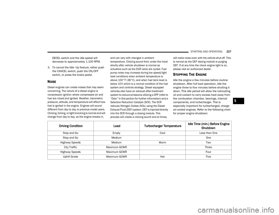
STOPPING THE ENGINE
Idle the engine a few minutes before routine
shutdown. After full load operation, idle the
engine three to five minutes before shutting it
down. This idle period will allow the lubricating
oil and coolant to carry excess heat away from
the combustion chamber, bearings, internal
components, and turbocharger. This is
especially important for turbocharged, charge
air-cooled engines. Refer to the following chart
for proper engine shutdown:
Driving Condition
Load Turbocharger Temperature Idle Time (min.) Before Engine
Shutdown
Stop and Go EmptyCoolLess than One
Stop and Go Medium -One
Highway Speeds MediumWarmTwo
City Traffic Maximum GCWR -Three
Highway Speeds Maximum GCWR -Four
Uphill Grade Maximum GCWR HotFive
5
20_DJD2_OM_EN_USC_t.book Page 227
Page 231 of 568

STARTING AND OPERATING229
Do Not Operate The Engine With Failed
Parts
All engine failures give some warning before the
parts fail. Be on the alert for changes in
performance, sounds, and visual evidence that
the engine requires service. Some important
clues are:
Engine misfiring or vibrating severely.
Sudden loss of power.
Unusual engine noises.
Fuel, oil or coolant leaks.
Sudden change, outside the normal oper -
ating range, in the engine operating tempera -
ture.
Excessive smoke.
Oil pressure drop.
ENGINE BLOCK HEATER — GAS ENGINE (IF
EQUIPPED)
The engine block heater warms the engine, and
permits quicker starts in cold weather. Connect
the cord to a standard 110-115 Volt AC
electrical outlet with a grounded, three-wire
extension cord.
The engine block heater cord is routed through
the grille by the right front tow hook.
It includes a removable cap that is secured by a
tethered strap. It also has a c-clip that is used
for storage when not in use for the Winter
months. During Winter months, remove the
heater cord wiring assembly from itself on the
c-clip.
The engine block heater must be plugged in at
least one hour to have an adequate warming
effect on the engine.
ENGINE BLOCK HEATER — DIESEL ENGINE
(IF EQUIPPED)
The engine block heater warms engine coolant
and permits quicker starts in cold weather.
Connect the heater cord to a ground-fault
interrupter protected 110–115 Volt AC
electrical outlet with a grounded, three-wire
extension cord.
The engine block heater cord is routed under
the hood to the right side and can be located
just behind the grille near the headlamp.
NOTE:
The engine block heater cord is a factory
installed option. If your vehicle is not equipped,
heater cords are available from an authorized
Mopar dealer.
The block heater must be plugged in at least
one hour to have an adequate warming effect
on the coolant.
CAUTION!
If oil pressure falls to less than normal
readings, shut the engine off immediately.
Failure to do so could result in immediate and
severe engine damage.
WARNING!
Remember to disconnect the engine block
heater cord before driving. Damage to the
110-115 Volt electrical cord could cause
electrocution.WARNING!
Remember to disconnect the cord before
driving. Damage to the 110–115 Volt
electrical cord could cause electrocution.
5
20_DJD2_OM_EN_USC_t.book Page 229
Page 232 of 568
230STARTING AND OPERATING
NOTE:
The block heater will require 110 Volts AC and
6.5 Amps to activate the heater element.
BLOCK HEATER USAGE
For ambient temperatures below 0°F (-18°C),
engine block heater usage is recommended.
For ambient temperatures below –20°F
(-29°C), engine block heater usage is required.
ENGINE BREAK-IN RECOMMENDATIONS —
GAS ENGINE
A long break-in period is not required for the
engine and drivetrain (transmission and axle) in
your vehicle.
Drive moderately during the first 300 miles
(500 km). After the initial 60 miles (100 km),
speeds up to 50 or 55 mph (80 or 90 km/h) are
desirable.
While cruising, brief full-throttle acceleration
within the limits of local traffic laws contributes
to a good break-in. Wide-open throttle
acceleration in low gear can be detrimental and
should be avoided. The engine oil installed in the engine at the
factory is a high-quality energy conserving type
lubricant. Oil changes should be consistent with
anticipated climate conditions under which
vehicle operations will occur. For the
recommended viscosity and quality grades,
refer to “Fluids And Lubricants” in “Technical
Specifications”.
NOTE:
A new engine may consume some oil during its
first few thousand miles (kilometers) of opera
-
tion. This should be considered a normal part of
the break-in and not interpreted as a problem.
Please check your oil level with the engine oil
indicator often during the break in period. Add
oil as required.
ENGINE BREAK-IN RECOMMENDATIONS —
DIESEL ENGINE
The Cummins® Turbo Diesel engine does not
require a break-in period due to its construction.
Normal operation is allowed, providing the
following recommendations are followed:
Warm up the engine before placing it under
load.
Do not operate the engine at idle for
prolonged periods.
Use the appropriate transmission gear to
prevent engine lugging.
Observe vehicle oil pressure and tempera -
ture indicators.
Check the coolant and oil levels frequently.
Vary throttle position at highway speeds
when carrying or towing significant weight.
CAUTION!
Never use Non-Detergent Oil or Straight
Mineral Oil in the engine or damage may
result.
20_DJD2_OM_EN_USC_t.book Page 230