engine Ram 3500 2020 Owner's Manual
[x] Cancel search | Manufacturer: RAM, Model Year: 2020, Model line: 3500, Model: Ram 3500 2020Pages: 568
Page 288 of 568
286STARTING AND OPERATING
TO VARY THE SPEED SETTING
To Increase Speed
While ACC is set, you can increase the set speed
by pushing the RES (+) button.
The speed increment shown is dependent on the
chosen speed unit of U.S. (mph) or Metric (km/h):
U.S. Speed (mph)
Pushing the RES (+) button once will result in a
1 mph increase in set speed. Each subsequent
tap of the button results in an increase of 1 mph.
If the button is continually pushed, the set
speed will continue to increase in 5 mph incre -
ments until the button is released. The increase
in set speed is reflected in the instrument
cluster display.
Metric Speed (km/h)
Pushing the RES (+) button once will result in
a 1 km/h increase in set speed. Each subse -
quent tap of the button results in an increase
of 1 km/h.
If the button is continually pushed, the set
speed will continue to increase in 10 km/h
increments until the button is released. The
increase in set speed is reflected in the
instrument cluster display.
To Decrease Speed
While ACC is set, the set speed can be
decreased by pushing the SET (-) button.
The speed decrement shown is dependent on
the chosen speed unit of U.S. (mph) or Metric
(km/h):
U.S. Speed (mph)
Pushing the SET (-) button once will result in
a 1 mph decrease in set speed. Each subse -
quent tap of the button results in a decrease
of 1 mph.
If the button is continually pushed, the set
speed will continue to decrease in 5 mph
decrements until the button is released. The
decrease in set speed is reflected in the
instrument cluster display. Metric Speed (km/h)
Pushing the SET (-) button once will result in
a 1 km/h decrease in set speed. Each subse -
quent tap of the button results in a decrease
of 1 km/h.
If the button is continually pushed, the set
speed will continue to decrease in 10 km/h
decrements until the button is released. The
decrease in set speed is reflected in the
instrument cluster display.
NOTE:
When you override and push the RES (+)
button or SET (-) button, the new set speed
will be the current speed of the vehicle.
When you use the SET (-) button to decel -
erate, if the engine’s braking power does not
slow the vehicle sufficiently to reach the set
speed, the brake system will automatically
slow the vehicle.
The ACC system decelerates the vehicle to a
full stop when following a target vehicle. If an
ACC host vehicle follows a target vehicle to a
standstill, after two seconds the driver will
either have to push the RES (+) button, or
apply the accelerator pedal to reengage the
ACC to the existing set speed.
WARNING!
The Resume function should only be used if
traffic and road conditions permit. Resuming
a set speed that is too high or too low for
prevailing traffic and road conditions could
cause the vehicle to accelerate or decelerate
too sharply for safe operation. Failure to
follow these warnings can result in a collision
and death or serious personal injury.
20_DJD2_OM_EN_USC_t.book Page 286
Page 321 of 568
STARTING AND OPERATING319
(Continued)
ENGINE RUNAWAY — DIESEL ENGINE
Diesel engine runaway is a rare condition
affecting diesel engines, where the engine
consumes its own lubrication oil and runs at
higher and higher RPM until it overspeeds to a
point where it destroys itself due to either
mechanical failure or engine seizure through
lack of lubrication.
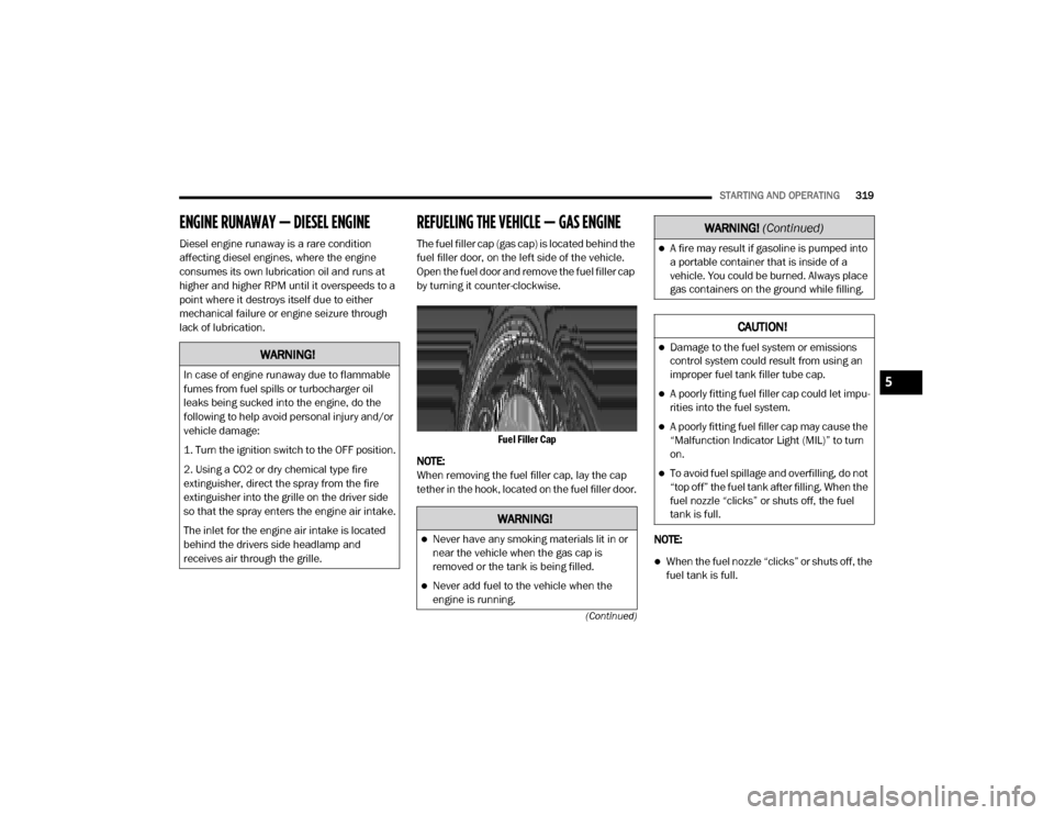
REFUELING THE VEHICLE — GAS ENGINE
The fuel filler cap (gas cap) is located behind the
fuel filler door, on the left side of the vehicle.
Open the fuel door and remove the fuel filler cap
by turning it counter-clockwise.
Fuel Filler Cap
NOTE:
When removing the fuel filler cap, lay the cap
tether in the hook, located on the fuel filler door.
NOTE:
When the fuel nozzle “clicks” or shuts off, the
fuel tank is full.
WARNING!
In case of engine runaway due to flammable
fumes from fuel spills or turbocharger oil
leaks being sucked into the engine, do the
following to help avoid personal injury and/or
vehicle damage:
1. Turn the ignition switch to the OFF position.
2. Using a CO2 or dry chemical type fire
extinguisher, direct the spray from the fire
extinguisher into the grille on the driver side
so that the spray enters the engine air intake.
The inlet for the engine air intake is located
behind the drivers side headlamp and
receives air through the grille.
WARNING!
Never have any smoking materials lit in or
near the vehicle when the gas cap is
removed or the tank is being filled.
Never add fuel to the vehicle when the
engine is running.
A fire may result if gasoline is pumped into
a portable container that is inside of a
vehicle. You could be burned. Always place
gas containers on the ground while filling.
CAUTION!
Damage to the fuel system or emissions
control system could result from using an
improper fuel tank filler tube cap.
A poorly fitting fuel filler cap could let impu-
rities into the fuel system.
A poorly fitting fuel filler cap may cause the
“Malfunction Indicator Light (MIL)” to turn
on.
To avoid fuel spillage and overfilling, do not
“top off” the fuel tank after filling. When the
fuel nozzle “clicks” or shuts off, the fuel
tank is full.
WARNING! (Continued)
5
20_DJD2_OM_EN_USC_t.book Page 319
Page 322 of 568
320STARTING AND OPERATING
Tighten the gas cap until you hear a “clicking”
sound. This is an indication that the gas cap
is tightened properly. The MIL in the instru -
ment cluster may turn on if the gas cap is not
secured properly. Make sure that the gas cap
is tightened each time the vehicle is refueled.
LOOSE FUEL FILLER CAP MESSAGE
If the vehicle diagnostic system
determines that the fuel filler cap is
loose, improperly installed, or
damaged, a loose gASCAP indicator
will display in the instrument cluster telltale
display area. Refer to “Instrument Cluster Display” in “Getting To Know Your Instrument
Panel” for further information. Tighten the fuel
filler cap properly and push the RIGHT button to
turn off the message. If the problem continues,
the message will appear the next time the
vehicle is started.
REFUELING THE VEHICLE — DIESEL ENGINE
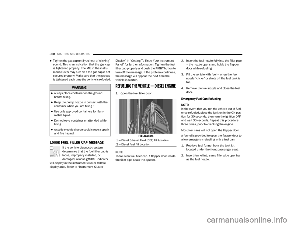
1. Open the fuel filler door.
Fill Locations
NOTE:
There is no fuel filler cap. A flapper door inside
the filler pipe seals the system. 2. Insert the fuel nozzle fully into the filler pipe
– the nozzle opens and holds the flapper
door while refueling.
3. Fill the vehicle with fuel – when the fuel nozzle “clicks” or shuts off the fuel tank is
full.
4. Remove the fuel nozzle and close the fuel door.
Emergency Fuel Can Refueling
NOTE:
In the event that you run the vehicle out of fuel,
once refueled, place the ignition in the ON posi -
tion for 30 seconds, then turn the ignition OFF
and wait 30 seconds. Repeat this procedure
three times, prior to cranking the engine.
Most fuel cans will not open the flapper door.
A funnel is provided to open the flapper door to
allow emergency refueling with a fuel can.
1. Retrieve fuel funnel from the jack kit located under the front passenger seat.
2. Insert funnel into same filler pipe opening as the fuel nozzle.
WARNING!
Always place container on the ground
before filling.
Keep the pump nozzle in contact with the
container when you are filling it.
Use only approved containers for flam -
mable liquid.
Do not leave container unattended while
filling.
A static electric charge could cause a spark
and fire hazard.
1 — Diesel Exhaust Fluid (DEF) Fill Location
2 — Diesel Fuel Fill Location
20_DJD2_OM_EN_USC_t.book Page 320
Page 323 of 568
STARTING AND OPERATING321
(Continued)
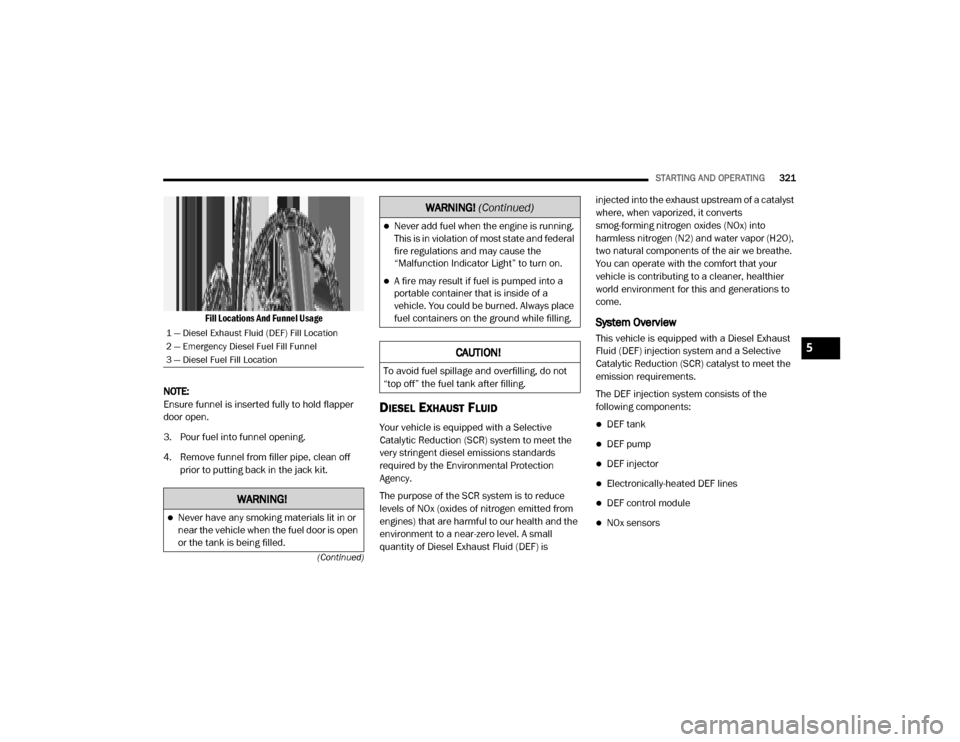
Fill Locations And Funnel Usage
NOTE:
Ensure funnel is inserted fully to hold flapper
door open.
3. Pour fuel into funnel opening.
4. Remove funnel from filler pipe, clean off prior to putting back in the jack kit.
DIESEL EXHAUST FLUID
Your vehicle is equipped with a Selective
Catalytic Reduction (SCR) system to meet the
very stringent diesel emissions standards
required by the Environmental Protection
Agency.
The purpose of the SCR system is to reduce
levels of NOx (oxides of nitrogen emitted from
engines) that are harmful to our health and the
environment to a near-zero level. A small
quantity of Diesel Exhaust Fluid (DEF) is injected into the exhaust upstream of a catalyst
where, when vaporized, it converts
smog-forming nitrogen oxides (NOx) into
harmless nitrogen (N2) and water vapor (H2O),
two natural components of the air we breathe.
You can operate with the comfort that your
vehicle is contributing to a cleaner, healthier
world environment for this and generations to
come.
System Overview
This vehicle is equipped with a Diesel Exhaust
Fluid (DEF) injection system and a Selective
Catalytic Reduction (SCR) catalyst to meet the
emission requirements.
The DEF injection system consists of the
following components:
DEF tank
DEF pump
DEF injector
Electronically-heated DEF lines
DEF control module
NOx sensors
1 — Diesel Exhaust Fluid (DEF) Fill Location
2 — Emergency Diesel Fuel Fill Funnel
3 — Diesel Fuel Fill Location
WARNING!
Never have any smoking materials lit in or
near the vehicle when the fuel door is open
or the tank is being filled.
Never add fuel when the engine is running.
This is in violation of most state and federal
fire regulations and may cause the
“Malfunction Indicator Light” to turn on.
A fire may result if fuel is pumped into a
portable container that is inside of a
vehicle. You could be burned. Always place
fuel containers on the ground while filling.
CAUTION!
To avoid fuel spillage and overfilling, do not
“top off” the fuel tank after filling.
WARNING!
(Continued)
5
20_DJD2_OM_EN_USC_t.book Page 321
Page 324 of 568

322STARTING AND OPERATING
Temperature sensors
SCR catalyst
UQS Sensor
Refer to “Instrument Cluster Display” in
“Getting To Know Your Instrument Panel” for
system messages and warnings.
NOTE:
Your vehicle is equipped with a DEF injection
system. You may occasionally hear an audible
clicking noise. This is normal operation.
The DEF pump will run for a period of time
after engine shutdown to purge the DEF
system. This is normal operation.
Diesel Exhaust Fluid Storage
Diesel Exhaust Fluid (DEF) is considered a very
stable product with a long shelf life. If DEF is
kept in temperatures between 10°F and 90°F
(-12°C and 32°C), it will last a minimum of one
year.
DEF is subject to freezing at the lowest
temperatures. For example, DEF may freeze at
temperatures at or below 12°F (-11°C). The
system has been designed to operate in this
environment. NOTE:
When working with DEF, it is important to know
that:
Any containers or parts that come into
contact with DEF must be DEF compatible
(plastic or stainless steel). Copper, brass,
aluminum, iron or non-stainless steel should
be avoided as they are subject to corrosion
by DEF.
If DEF is spilled, it should be wiped up
completely.
Adding Diesel Exhaust Fluid
The DEF gauge (located on the instrument
cluster) will display the level of DEF remaining in
the tank. Refer to “Instrument Cluster” and
“Instrument Cluster Descriptions” in “Getting To
Know Your Instrument Panel” for further
information.
NOTE:
Driving conditions (altitude, vehicle speed,
load, etc.) will affect the amount of DEF that
is used in your vehicle.
Another factor is that outside temperature
can affect DEF consumption. In cold condi
-
tions, 12°F (-11°C) and below, the DEF gauge needle can stay on a fixed position and
may not move for extended periods of time.
This is a normal function of the system.
There is an electric heater inside the DEF
tank that automatically works when neces
-
sary. And if the DEF supply does freeze, the
truck will operate normally until it thaws.
DEF Fill Procedure
NOTE:
Refer to “Fluids And Lubricants” in “Technical
Specifications” for the correct fluid type.
1. Remove cap from DEF tank (located on driver’s side of the vehicle or in fuel door).
Fill Locations
1 — Diesel Exhaust Fluid (DEF) Fill Location
2 — Diesel Fuel Fill Location
20_DJD2_OM_EN_USC_t.book Page 322
Page 325 of 568

STARTING AND OPERATING323
(Continued)
2. Insert DEF fill adapter/nozzle into DEF tank filler neck.
NOTE:
The DEF gauge may take up to five
seconds to update after adding a gallon
or more of Diesel Exhaust Fluid (DEF) to
the DEF tank. If you have a fault related
to the DEF system, the gauge may not
update to the new level. See an autho -
rized dealer for service.
The DEF gauge may also not immediately
update after a refill if the temperature of
the DEF fluid is below 12°F (-11°C). The
DEF line heater will possibly warm up the
DEF fluid and allow the gauge to update
after a period of run time. Under very cold
conditions, it is possible that the gauge
may not reflect the new fill level for
several drives.
Excessive overfilling of the DEF tank can
result in a MIL lamp/fault code and inac-
curate level readings. 3. Stop filling the DEF tank immediately when
any of the following happen: DEF stops
flowing from the fill bottle into the DEF tank,
DEF splashes out the filler neck, or a DEF
pump nozzle automatically shuts off.
4. Reinstall cap onto DEF tank.
Filling The Def Tank In Cold Climates
Since DEF will begin to freeze at 12°F (-11°C),
your vehicle is equipped with an automatic DEF
heating system. This allows the DEF injection
CAUTION!
To avoid DEF spillage, and possible
damage to the DEF tank from overfilling, do
not “top off” the DEF tank after filling.
DO NOT OVERFILL. DEF will freeze below
12ºF (-11ºC). The DEF system is designed
to work in temperatures below the DEF
freezing point, however, if the tank is over -
filled and freezes, the system could be
damaged.
When DEF is spilled, clean the area imme -
diately with water and use an absorbent
material to soak up the spills on the ground.
Do not attempt to start your engine if DEF is
accidentally added to the diesel fuel tank
as it can result in severe damage to your
engine, including but not limited to failure
of the fuel pump and injectors.
Never add anything other than DEF to the
tank – especially any form of hydrocarbon
such as diesel fuel, fuel system additives,
gasoline, or any other petroleum-based
product. Even a very small amount of these,
less than 100 parts per million or less than
1 oz. per 78 Gallons (295 Liters) will
contaminate the entire DEF system and will
require replacement. If owners use a
container, funnel or nozzle when refilling
the tank, it should either be new or one that
is has only been used for adding DEF.
Mopar provides an attachable nozzle with
its DEF for this purpose.
CAUTION! (Continued)
5
20_DJD2_OM_EN_USC_t.book Page 323
Page 328 of 568

326STARTING AND OPERATING
Gross Axle Weight Rating (GAWR)
The GAWR is the maximum capacity of the front
and rear axles. Distribute the load over the front
and rear axles evenly. Make sure that you do
not exceed either front or rear GAWR. Refer to
“Vehicle Loading/Vehicle Certification Label” in
“Starting And Operating” for further
information.
Tongue Weight (TW)
The tongue weight is the downward force
exerted on the hitch ball by the trailer. You must
consider this as part of the load on your vehicle.
Trailer Frontal Area
The frontal area is the maximum height
multiplied by the maximum width of the front of
a trailer.
Trailer Sway Control
The trailer sway control can be a mechanical
telescoping link that can be installed between
the hitch receiver and the trailer tongue that
typically provides adjustable friction associated
with the telescoping motion to dampen any
unwanted trailer swaying motions while
traveling.
If equipped, the electronic Trailer Sway Control
(TSC) recognizes a swaying trailer and
automatically applies individual wheel brakes
and/or reduces engine power to attempt to
eliminate the trailer sway.
Weight-Carrying Hitch
A weight-carrying hitch supports the trailer
tongue weight, just as if it were luggage located
at a hitch ball or some other connecting point of
the vehicle. These kinds of hitches are the most
popular on the market today and they are
commonly used to tow small and medium sized
trailers.
Weight-Distributing Hitch
A weight-distributing system works by applying
leverage through spring (load) bars. They are
typically used for heavier loads to distribute
trailer tongue weight to the tow vehicle's front
axle and the trailer axle(s). When used in
accordance with the manufacturer's directions,
it provides for a more level ride, offering more
consistent steering and brake control, thereby
enhancing towing safety. The addition of a
friction/hydraulic sway control also dampens
sway caused by traffic and crosswinds and
contributes positively to tow vehicle and trailer
stability. Trailer Sway Control (TSC) and a weight
distributing (load equalizing) hitch are
recommended for heavier Tongue Weights (TW)
and may be required depending on vehicle and
trailer configuration/loading to comply with
GAWR requirements.
WARNING!
It is important that you do not exceed the
maximum front or rear GAWR. A dangerous
driving condition can result if either rating is
exceeded. You could lose control of the
vehicle and have a collision.
20_DJD2_OM_EN_USC_t.book Page 326
Page 329 of 568

STARTING AND OPERATING327
With Weight-Distributing Hitch (Correct) Without Weight-Distributing Hitch (Incorrect)
Improper Adjustment Of Weight-Distributing Hitch (Incorrect)
Recommended Distribution Hitch Adjustment
Towing With 2500/3500 Air Suspension
1. Position the truck to be ready to connect to
the trailer (do not connect the trailer).
NOTE:
Normal Ride Height (NRH) or Alternate Trailer
Height (ATH) can be used. The vehicle must
remain in the engine running position while
attaching a trailer for proper leveling of the air
suspension system. It may not be possible to
enter Alternate Trailer Height (ATH) while lightly
loaded.
2. Measure the height of the top of the front wheel opening on the fender to ground, this
is height H1.
3. Attach the trailer to the vehicle without the weight distribution bars connected.
4. Measure the height of the top of the front wheel opening on the fender to ground, this
is height H2.
WARNING!
An improperly adjusted weight distributing
hitch system may reduce handling, stability
and braking performance and could result
in a collision.
Weight distributing systems may not be
compatible with surge brake couplers.
Consult with your hitch and trailer manufac -
turer or a reputable Recreational Vehicle
dealer for additional information.
5
20_DJD2_OM_EN_USC_t.book Page 327
Page 332 of 568

330STARTING AND OPERATING
(Continued)
TRAILER TOWING WEIGHTS (MAXIMUM
T
RAILER WEIGHT RATINGS)
NOTE:
For trailer towing information (maximum trailer
weight ratings) refer to the following website
addresses:
ramtrucks.com/en/towing_guide/
ramtruck.ca (Canada)
rambodybuilder.com
TRAILER AND TONGUE WEIGHT
Weight Distribution
Consider the following items when computing
the weight on the rear axle of the vehicle:
The tongue weight of the trailer.
The weight of any other type of cargo or
equipment put in or on your vehicle.
The weight of the driver and all passengers.
NOTE:
Remember that everything put into or on the
trailer adds to the load on your vehicle. Also,
additional factory-installed options or
dealer-installed options must be considered as
part of the total load on your vehicle. Refer to
the “Tire And Loading Information” placard for
the maximum combined weight of occupants
and cargo for your vehicle.
TOWING REQUIREMENTS
To promote proper break-in of your new vehicle
drivetrain components, the following guidelines
are recommended.
Perform the maintenance listed in the
“Scheduled Servicing”. Refer to “Scheduled
Servicing” in “Servicing And Maintenance” for the
proper maintenance intervals. When towing a
trailer, never exceed the GAWR or GCWR ratings.
CAUTION!
Do not tow a trailer at all during the first
500 miles (805 km) the new vehicle is driven.
The engine, axle or other parts could be
damaged.
Then, during the first 500 miles (805 km) that
a trailer is towed, do not drive over 50 mph
(80 km/h) and do not make starts at full
throttle. This helps the engine and other parts
of the vehicle wear in at the heavier loads.
WARNING!
Make certain that the load is secured in the
trailer and will not shift during travel. When
trailering cargo that is not fully secured,
dynamic load shifts can occur that may be diffi
-
cult for the driver to control. You could lose
control of your vehicle and have a collision.
20_DJD2_OM_EN_USC_t.book Page 330
Page 333 of 568
STARTING AND OPERATING331
(Continued)
Towing Requirements — Tires
Do not attempt to tow a trailer while using a
compact spare tire.
Do not drive more than 50 mph (80 km/h) when towing while using a full size spare tire.
Proper tire inflation pressures are essential
to the safe and satisfactory operation of your
vehicle. Refer to “Tires” in “Servicing And
Maintenance” for proper tire inflation proce -
dures.
Check the trailer tires for proper tire inflation
pressures before trailer usage.
Check for signs of tire wear or visible tire
damage before towing a trailer. Refer to
“Tires” in “Servicing And Maintenance” for
the proper inspection procedure.
When replacing tires, refer to “Tires” in
“Servicing And Maintenance” for the proper
tire replacement procedures. Replacing tires
with a higher load carrying capacity will not
increase the vehicle's GVWR and GAWR
limits.
Towing Requirements — Trailer Brakes
Do not interconnect the hydraulic brake
system or vacuum system of your vehicle
with that of the trailer. This could cause inad -
equate braking and possible personal injury.
An electronically actuated trailer brake
controller is required when towing a trailer
with electronically actuated brakes. When
towing a trailer equipped with a hydraulic
surge actuated brake system, an electronic
brake controller is not required.
Trailer brakes are recommended for trailers
over 1,000 lbs (453 kg) and required for
trailers in excess of 2,000 lbs (907 kg).
When hauling cargo or towing a trailer, do
not overload your vehicle or trailer. Over -
loading can cause a loss of control, poor
performance or damage to brakes, axle,
engine, transmission, steering, suspension,
chassis structure or tires.
Safety chains must always be used
between your vehicle and trailer. Always
connect the chains to the hook retainers of
the vehicle hitch. Cross the chains under
the trailer tongue and allow enough slack
for turning corners.
Vehicles with trailers should not be parked
on a grade. When parking, apply the
parking brake on the tow vehicle. Put the
tow vehicle transmission in PARK. For
four-wheel drive vehicles, make sure the
transfer case is not in NEUTRAL. Always,
block or "chock" the trailer wheels.
GCWR must not be exceeded.
WARNING! (Continued)
Total weight must be distributed between
the tow vehicle and the trailer such that the
following four ratings are not exceeded :
GVWR
GTW
GAWR
Tongue weight rating for the trailer
hitch utilized.
WARNING! (Continued)
5
20_DJD2_OM_EN_USC_t.book Page 331