turn signal Ram 3500 2020 User Guide
[x] Cancel search | Manufacturer: RAM, Model Year: 2020, Model line: 3500, Model: Ram 3500 2020Pages: 568
Page 139 of 568
GETTING TO KNOW YOUR INSTRUMENT PANEL137
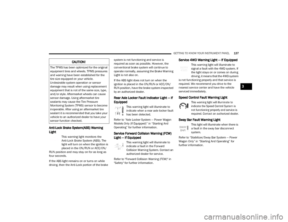
Anti-Lock Brake System(ABS) Warning
Light
This warning light monitors the
Anti-Lock Brake System (ABS). The
light will turn on when the ignition is
placed in the ON/RUN or ACC/ON/
RUN position and may stay on for as long as
four seconds.
If the ABS light remains on or turns on while
driving, then the Anti-Lock portion of the brake system is not functioning and service is
required as soon as possible. However, the
conventional brake system will continue to
operate normally, assuming the Brake Warning
Light is not also on.
If the ABS light does not turn on when the
ignition is placed in the ON/RUN or ACC/ON/
RUN position, have the brake system inspected
by an authorized dealer.
Rear Axle Locker Fault Indicator Light — If
Equipped
This warning light will illuminate to
indicate when a rear axle locker fault
has been detected.
Refer to “Axle Locker System — Power Wagon
Models Only (If Equipped)” in “Starting And
Operating” for further information.
Service Forward Collision Warning (FCW)
Light — If Equipped
This warning light will illuminate to
indicate a fault in the Forward
Collision Warning System. Contact an
authorized dealer for service.
Refer to "Forward Collision Warning (FCW)" in
"Safety" for further information.
Service 4WD Warning Light — If Equipped
This warning light will illuminate to
signal a fault with the 4WD system. If
the light stays on or comes on during
driving, it means that the 4WD system
is not functioning properly and that service is
required. We recommend you drive to the
nearest service center and have the vehicle
serviced immediately.
Speed Control Fault Warning Light
This warning light will illuminate to
indicate the Speed Control System is
not functioning properly and service is
required. Contact an authorized dealer.
Sway Bar Fault Warning Light
This light will illuminate when there is
a fault in the sway bar disconnect
system.
Refer to “Stabilizer/Sway Bar System — Power
Wagon Only” in “Starting And Operating” for
further information.
CAUTION!
The TPMS has been optimized for the original
equipment tires and wheels. TPMS pressures
and warning have been established for the
tire size equipped on your vehicle.
Undesirable system operation or sensor
damage may result when using replacement
equipment that is not of the same size, type,
and/or style. Aftermarket wheels can cause
sensor damage. Using aftermarket tire
sealants may cause the Tire Pressure
Monitoring System (TPMS) sensor to become
inoperable. After using an aftermarket tire
sealant it is recommended that you take your
vehicle to an authorized dealer to have your
sensor function checked.
3
20_DJD2_OM_EN_USC_t.book Page 137
Page 143 of 568
GETTING TO KNOW YOUR INSTRUMENT PANEL141
to provide visual and torque warnings if an
unintentional lane departure occurs.
Refer to “LaneSense — If Equipped” in “Starting
And Operating” for further information.
Front Fog Indicator Light — If Equipped
This indicator light will illuminate
when the front fog lights are on.
Refer to “Exterior Lights” in “Getting
To Know Your Vehicle” for further information.
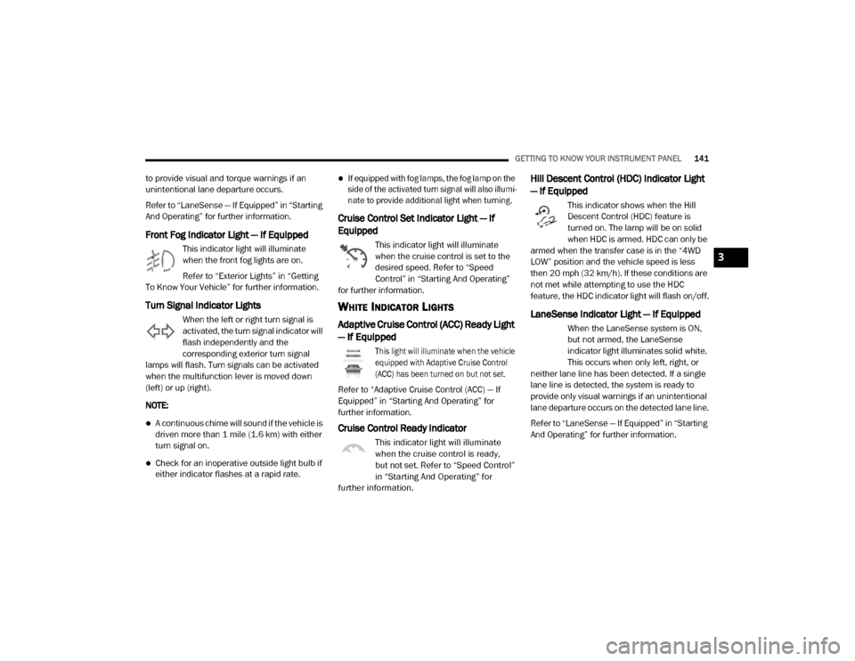
Turn Signal Indicator Lights
When the left or right turn signal is
activated, the turn signal indicator will
flash independently and the
corresponding exterior turn signal
lamps will flash. Turn signals can be activated
when the multifunction lever is moved down
(left) or up (right).
NOTE:
A continuous chime will sound if the vehicle is
driven more than 1 mile (1.6 km) with either
turn signal on.
Check for an inoperative outside light bulb if
either indicator flashes at a rapid rate.
If equipped with fog lamps, the fog lamp on the
side of the activated turn signal will also illumi -
nate to provide additional light when turning.
Cruise Control Set Indicator Light — If
Equipped
This indicator light will illuminate
when the cruise control is set to the
desired speed. Refer to “Speed
Control” in “Starting And Operating”
for further information.
WHITE INDICATOR LIGHTS
Adaptive Cruise Control (ACC) Ready Light
— If Equipped
This light will illuminate when the vehicle
equipped with Adaptive Cruise Control
(ACC) has been turned on but not set.
Refer to “Adaptive Cruise Control (ACC) — If
Equipped” in “Starting And Operating” for
further information.
Cruise Control Ready Indicator
This indicator light will illuminate
when the cruise control is ready,
but not set. Refer to “Speed Control”
in “Starting And Operating” for
further information.
Hill Descent Control (HDC) Indicator Light
— If Equipped
This indicator shows when the Hill
Descent Control (HDC) feature is
turned on. The lamp will be on solid
when HDC is armed. HDC can only be
armed when the transfer case is in the “4WD
LOW” position and the vehicle speed is less
then 20 mph (32 km/h). If these conditions are
not met while attempting to use the HDC
feature, the HDC indicator light will flash on/off.
LaneSense Indicator Light — If Equipped
When the LaneSense system is ON,
but not armed, the LaneSense
indicator light illuminates solid white.
This occurs when only left, right, or
neither lane line has been detected. If a single
lane line is detected, the system is ready to
provide only visual warnings if an unintentional
lane departure occurs on the detected lane line.
Refer to “LaneSense — If Equipped” in “Starting
And Operating” for further information.
3
20_DJD2_OM_EN_USC_t.book Page 141
Page 158 of 568

156SAFETY
The BSM system is designed not to issue an
alert on stationary objects such as guardrails,
posts, walls, foliage, berms, snow banks, car
washes etc. However, occasionally the system
may alert on such objects. This is normal
operation and your vehicle does not require
service.
The BSM system will not alert you of objects that
are traveling in the opposite direction of the
vehicle in adjacent lanes.
Opposing Traffic
Rear Cross Path (RCP)
The Rear Cross Path (RCP) feature is intended
to aid the driver when backing out of parking
spaces where their vision of oncoming vehicles
may be blocked. Proceed slowly and cautiously
out of the parking space until the rear end of the
vehicle is exposed. The RCP system will then
have a clear view of the cross traffic and if an
oncoming vehicle is detected, alert the driver.
RCP Detection Zones
RCP monitors the rear detection zones on both
sides of the vehicle, for objects that are moving
toward the side of the vehicle with a minimum
speed of approximately 3 mph (5 km/h), to
objects moving a maximum of approximately
20 mph (32 km/h), such as in parking lot
situations.
NOTE:
In a parking lot situation, oncoming vehicles can
be obscured by vehicles parked on either side.
If the sensors are blocked by other structures or
vehicles, the system will not be able to alert the
driver.
WARNING!
The Blind Spot Monitoring system is only an
aid to help detect objects in the blind spot
zones. The BSM system is not designed to
detect pedestrians, bicyclists, or animals.
Even if your vehicle is equipped with the BSM
system, always check your vehicle’s mirrors,
glance over your shoulder, and use your turn
signal before changing lanes. Failure to do so
can result in serious injury or death.
20_DJD2_OM_EN_USC_t.book Page 156
Page 159 of 568

SAFETY157
When RCP is on and the vehicle is in REVERSE,
the driver is alerted using both the visual and
audible alarms, including reducing the radio
volume.
Modes Of Operation
Three selectable modes of operation are
available in the Uconnect System.
Refer to “Uconnect Settings” in “Multimedia”
for further information. Blind Spot Alert Lights Only
When operating in Blind Spot Alert mode, the
BSM system will provide a visual alert in the
appropriate side view mirror based on a
detected object. However, when the system is
operating in Rear Cross Path (RCP) mode, the
system will respond with both visual and
audible alerts when a detected object is
present. Whenever an audible alert is
requested, the radio is muted.
Blind Spot Alert Lights/Chime
When operating in Blind Spot Alert Lights/
Chime mode, the BSM system will provide a
visual alert in the appropriate side view mirror
based on a detected object. If the turn signal is
then activated, and it corresponds to an alert
present on that side of the vehicle, an audible
chime will also be sounded. Whenever a turn
signal and detected object are present on the
same side at the same time, both the visual and
audible alerts will be issued. In addition to the
audible alert the radio (if on) will also be muted.
NOTE:
Whenever an audible alert is requested by the
BSM system, the radio is also muted.
When the system is in RCP, the system shall
respond with both visual and audible alerts
when a detected object is present. Whenever
an audible alert is requested, the radio is also
muted. Turn/hazard signal status is ignored;
the RCP state always requests the chime.
Blind Spot Alert Off
When the BSM system is turned off there will be
no visual or audible alerts from either the BSM
or RCP systems.
NOTE:
The BSM system will store the current operating
mode when the vehicle is shut off. Each time
the vehicle is started the previously stored
mode will be recalled and used.Trailer Merge Assist
NOTE:
When Trailer Merge Assist is activated, Rear
Cross Path is disabled.
WARNING!
Rear Cross Path Detection (RCP) is not a back
up aid system. It is intended to be used to
help a driver detect an oncoming vehicle in a
parking lot situation. Drivers must be careful
when backing up, even when using RCP.
Always check carefully behind your vehicle,
look behind you, and be sure to check for
pedestrians, animals, other vehicles,
obstructions, and blind spots before backing
up. Failure to do so can result in serious
injury or death.
4
20_DJD2_OM_EN_USC_t.book Page 157
Page 162 of 568

160SAFETY
General Information
The following regulatory statement applies to all
Radio Frequency (RF) devices equipped in this
vehicle:
This device complies with Part 15 of the FCC
Rules and with Innovation, Science and
Economic Development Canada license-exempt
RSS standard(s). Operation is subject to the
following two conditions:
1. This device may not cause harmful
interference, and
2. This device must accept any interference received, including interference that may
cause undesired operation. Le présent appareil est conforme aux CNR
d`Innovation, Science and Economic
Development applicables aux appareils radio
exempts de licence. L'exploitation est autorisée
aux deux conditions suivantes:
1. l'appareil ne doit pas produire de
brouillage, et
2. l'utilisateur de l'appareil doit accepter tout brouillage radioélectrique subi, même si le
brouillage est susceptible d'en compro -
mettre le fonctionnement.
La operación de este equipo está sujeta a las
siguientes dos condiciones:
1. es posible que este equipo o dispositivo no cause interferencia perjudicial y
2. este equipo o dispositivo debe aceptar cualquier interferencia, incluyendo la que
pueda causar su operación no deseada.
NOTE:
Changes or modifications not expressly
approved by the party responsible for compli -
ance could void the user’s authority to operate
the equipment.
FORWARD COLLISION WARNING (FCW)
W
ITH MITIGATION — IF EQUIPPED
The Forward Collision Warning (FCW) system
provides the driver with audible, visual warnings
(within the instrument cluster display), and may
apply a haptic warning in the form of a brake
jerk, to warn the driver when it detects a
potential frontal collision. The warnings are
intended to provide the driver with enough time
to react, avoid or mitigate the potential collision.
NOTE:
FCW monitors the information from the forward
looking sensors as well as Electronic Brake
Controller (EBC), to calculate the probability of a
forward collision. When the system determines
that a forward collision is probable, the driver
will be provided with audible and visual warn-
ings as well as a possible haptic warning in the
form of a brake jerk.
If the driver does not take action based upon
these progressive warnings, then the system
will provide a limited level of active braking to
help slow the vehicle and mitigate the potential
forward collision. If the driver reacts to the warn -
ings by braking and the system determines that
the driver intends to avoid the collision by
WARNING!
The Blind Spot Monitoring system is only an
aid to help detect objects in the blind spot
zones. The BSM system is not designed to
detect pedestrians, bicyclists, or animals.
Even if your vehicle is equipped with the BSM
system, always check your vehicle’s mirrors,
glance over your shoulder, and use your turn
signal before changing lanes. Failure to do so
can result in serious injury or death.
20_DJD2_OM_EN_USC_t.book Page 160
Page 168 of 568
166SAFETY
Should this occur, you should stop as soon as
possible and inflate the tires with a low pressure
condition (those in a different color in the
instrument cluster graphic) to the vehicle’s
recommended cold placard pressure inflation
value as shown in the "Inflate to XX" message.
Once the system receives the updated tire
pressures, the system will automatically
update, the graphic display in the instrument
cluster will return to its original color, and the
“Tire Pressure Monitoring Telltale Light” will
turn off. The vehicle may need to be driven for
up to 20 minutes above 15 mph (24 km/h) in
order for the TPMS to receive this information.
NOTE:
When filling warm tires, the tire pressure may
need to be increased up to an additional 4 psi
(28 kPa) above the recommended cold placard
pressure in order to turn the Tire Pressure Moni -
toring Warning Light off.
Service TPMS Warning
If a system fault is detected, the “Tire Pressure
Monitoring Warning Light” will flash on and off
for 75 seconds and then remain on solid. In
addition, the instrument cluster will display a "SERVICE TPM SYSTEM" message for a
minimum of five seconds and then display
dashes (- -) in place of the pressure value to
indicate which sensor is not being received.
If the ignition switch is cycled, this sequence will
repeat, providing the system fault still exists. If
the system fault no longer exists, the “Tire
Pressure Monitoring Warning Light” will no
longer flash, and the "SERVICE TPM SYSTEM"
message will no longer display, and a pressure
value will display in place of the dashes. A
system fault can occur due to any of the
following:
Signal interference due to electronic devices
or driving next to facilities emitting the same
radio frequencies as the TPM sensors.
Installing aftermarket window tinting that
contains materials that may block radio wave
signals.
Accumulation of snow or ice around the
wheels or wheel housings.
Using tire chains on the vehicle.
Using wheels/tires not equipped with TPM
sensors.A system fault may occur due to an incorrect
TPM sensor location condition. When a system
fault occurs due to an incorrect TPM sensor
location, the “Tire Pressure Monitoring Warning
Light” will flash on and off for 75 seconds and
then remain on solid. The system fault will also
sound a chime. In addition, the instrument
cluster will display a “Tire Pressure Temporarily
Unavailable” message in place of the tire
pressure display screen. If the ignition switch is
cycled, this sequence will repeat, providing the
system fault still exists. If the system fault no
longer exists, the “Tire Pressure Monitoring
Warning Light” will no longer flash and the tire
pressure display screen will be displayed
showing the tire pressure values the correct
locations.
Vehicles With Non-Matching Full Size Spare Or
Compact Spare
The non-matching full size spare or compact
spare tire does not have a TPM sensor.
Therefore, the TPMS will not monitor the
pressure in the non-matching full size spare
or compact spare tire.
20_DJD2_OM_EN_USC_t.book Page 166
Page 214 of 568
212SAFETY
PERIODIC SAFETY CHECKS YOU SHOULD
M
AKE OUTSIDE THE VEHICLE
Tires
Examine tires for excessive tread wear and
uneven wear patterns. Check for stones, nails,
glass, or other objects lodged in the tread or
sidewall. Inspect the tread for cuts and cracks.
Inspect sidewalls for cuts, cracks, and bulges.
Check the wheel bolts for tightness. Check the
tires (including spare) for proper cold inflation
pressure.
Lights
Have someone observe the operation of brake
lights and exterior lights while you work the
controls. Check turn signal and high beam
indicator lights on the instrument panel.
Door Latches
Check for proper closing, latching, and locking.
Fluid Leaks
Check area under the vehicle after overnight
parking for fuel, coolant, oil, or other fluid leaks.
Also, if gasoline fumes are detected or if fuel, or
brake fluid leaks are suspected, the cause
should be located and corrected immediately.
It is recommended to only use mild soap
and water to clean your floor mats. After
cleaning, always check your floor mat has
been properly installed and is secured to
your vehicle using the floor mat fasteners
by lightly pulling mat.
WARNING! (Continued)
20_DJD2_OM_EN_USC_t.book Page 212
Page 264 of 568
262STARTING AND OPERATING
The Basics Of Off-Road Driving
You will encounter many types of terrain driving
off-road. You should be familiar with the terrain
and area before proceeding. There are many
types of surface conditions: hard packed dirt,
gravel, rocks, grass, sand, mud, snow and ice.
Every surface has a different effect on your
vehicle's steering, handling and traction.
Controlling your vehicle is one of the keys to
successful off-road driving, so always keep a
firm grip on the steering wheel and maintain a
good driving posture. Avoid sudden
accelerations, turns or braking. In most cases
there are no road signs, posted speed limits or
signal lights. Therefore you will need to use your
own good judgment on what is safe and what
isn't. When on a trail you should always be
looking ahead for surface obstacles and
changes in terrain. The key is to plan your future
driving route while remembering what you are
currently driving over.
When To Use Low Range
When driving off-road, shift into 4WD LOW for
additional traction or to improve handling and
control on slippery or difficult terrain. Due to the
lower gearing, low range will allow the engine to
operate in a higher power range. This will allow
you to idle over obstacles and down hills, with
improved control and less effort. Also, use 4WD
LOW in rain, ice, snow, mud, and sand to get
heavy loads rolling, improve traction, or
whenever 4WD HIGH traction will not do the job.
DRIVING IN SNOW, MUD AND SAND
There is a drastic reduction in traction when
driving in snow, mud or sand. The vehicle will be
less responsive to steering, acceleration and
braking inputs. Therefore you should accelerate
slowly, leave greater stopping distances and
avoid abrupt vehicle maneuvers. You want to
keep a slow constant steady pace. The key is to
maintain the vehicle's momentum.
Snow – In heavy snow or for additional
control and traction at slower speeds, shift
the transmission to a low gear and shift the
transfer case to 4WD LOW if necessary. Do
not shift to a lower gear than necessary to
maintain headway. Over-revving the engine
can spin the wheels and traction will be lost.
If you start to slow to a stop, try turning your
steering wheel no more than a quarter turn
quickly back and forth, while still applying
throttle. This will allow the tires to get a fresh
"bite" and help maintain your momentum.
Mud – Deep mud creates a great deal of
suction around the tires and is very difficult to
get through. You should use 4WD LOW with a
gear low enough to maintain your momentum
without shifting. If you start to slow to a stop,
try turning your steering wheel no more than
a quarter turn quickly back and forth for addi -
tional traction. Mud holes pose an increased
threat of vehicle damage and getting stuck.
WARNING!
Always wear your seat belt and firmly tie down
cargo. Unsecured cargo can become
projectiles in an off-road situation.
CAUTION!
Never park your vehicle over dry grass or
other combustible materials. The heat from
your vehicle exhaust system could cause a
fire.
CAUTION!
On icy or slippery roads, do not downshift at
high engine RPMs or vehicle speeds because
engine braking may cause skidding and loss
of control.
20_DJD2_OM_EN_USC_t.book Page 262
Page 290 of 568
288STARTING AND OPERATING
The system automatically defaults to the
longest distance setting. To decrease the
distance setting, push the Distance Button and
release. Each time the button is pushed, the
distance setting decreases by one bar. Once the
shortest setting is reached, if the button is
pushed again it will reset to the default setting
(longest).
If there is no vehicle ahead, the vehicle will
maintain the set speed. If a slower moving
vehicle is detected in the same lane, the
instrument cluster displays the ACC Set With
Target Indicator Light, and the system adjusts
vehicle speed automatically to maintain the
distance setting, regardless of the set speed.
The vehicle will then maintain the set distance
until:
The vehicle ahead accelerates to a speed
above the set speed.
The vehicle ahead moves out of your lane or
view of the sensor.
The distance setting is changed.
The system disengages. (Refer to “Activating
Adaptive Cruise Control (ACC)” in this
chapter. The maximum braking applied by ACC is limited;
however, the driver can always apply the brakes
manually, if necessary.
NOTE:
The brake lights will illuminate whenever the
ACC system applies the brakes.
A Proximity Warning will alert the driver if ACC
predicts that its maximum braking level is not
sufficient to maintain the set distance. If this
occurs, a visual alert “BRAKE” will flash in the
instrument cluster display and a chime will
sound while ACC continues to apply its
maximum braking capacity.
Brake Alert
NOTE:
The “BRAKE!” Screen in the instrument cluster
display is a warning for the driver to take action
and does not necessarily mean that the
Forward Collision Warning system is applying
the brakes autonomously.
Trailer Detect — If Equipped
When a trailer is detected, the ACC system
automatically defaults to the longest setting (four
bars). The setting can be overridden by pushing
the Distance Button on the steering wheel.
OVERTAKE AID
When driving with ACC engaged and following a
vehicle, the system will provide an additional
acceleration up to the ACC set speed to assist in
passing the vehicle. This additional acceleration
is triggered when the driver utilizes the left turn
signal and will only be active when passing on
the left hand side.
20_DJD2_OM_EN_USC_t.book Page 288
Page 308 of 568
306STARTING AND OPERATING
Clean the ParkSense sensors regularly,
taking care not to scratch or damage them.
The sensors must not be covered with ice,
snow, slush, mud, dirt or debris. Failure to do
so can result in the system not working prop -
erly. The ParkSense system might not detect
an obstacle behind or in front of the fascia/
bumper, or it could provide a false indication
that an obstacle is behind or in front of the
fascia/bumper.
Use the ParkSense switch to turn the Park -
Sense system off if obstacles such as bicycle
carriers, trailer hitches, etc. are placed within
18 inches (45 cm) from the rear fascia/
bumper. Failure to do so can result in the
system misinterpreting a close obstacle as a
sensor problem, causing the “Front/Rear
ParkSense Unavailable Service Required”
message to be appear in the instrument
cluster display.
On vehicles equipped with a tailgate, Park -
Sense should be disabled when the tailgate
is in the lowered or open position. A lowered
tailgate could provide a false indication that
an obstacle is behind the vehicle.
LANESENSE — IF EQUIPPED
LANESENSE OPERATION
The LaneSense system is operational at speeds
above 37 mph (60 km/h) and below 112 mph
(180 km/h). It uses a forward looking camera to
detect lane markings and measure vehicle
position within the lane boundaries.
When both lane markings are detected and the
driver unintentionally drifts out of the lane while
no turn signal has been applied OR the driver
departs the lane on the opposite side of the
WARNING!
Drivers must be careful when backing up
even when using ParkSense. Always check
carefully behind your vehicle, look behind
you, and be sure to check for pedestrians,
animals, other vehicles, obstructions, and
blind spots before backing up. You are
responsible for safety and must continue to
pay attention to your surroundings. Failure
to do so can result in serious injury or
death.
Before using ParkSense, it is strongly
recommended that the ball mount and
hitch ball assembly is disconnected from
the vehicle when the vehicle is not used for
towing. Failure to do so can result in injury
or damage to vehicles or obstacles
because the hitch ball will be much closer
to the obstacle than the rear fascia when
the loudspeaker sounds the continuous
tone. Also, the sensors could detect the ball
mount and hitch ball assembly, depending
on its size and shape, giving a false indica -
tion that an obstacle is behind the vehicle.
CAUTION!
ParkSense is only a parking aid and it is
unable to recognize every obstacle,
including small obstacles. Parking curbs
might be temporarily detected or not
detected at all. Obstacles located above or
below the sensors will not be detected
when they are in close proximity.
The vehicle must be driven slowly when
using ParkSense in order to be able to stop
in time when an obstacle is detected. It is
recommended that the driver looks over
his/her shoulder when using ParkSense.
20_DJD2_OM_EN_USC_t.book Page 306