turn signal Ram 3500 2020 Owner's Guide
[x] Cancel search | Manufacturer: RAM, Model Year: 2020, Model line: 3500, Model: Ram 3500 2020Pages: 568
Page 309 of 568
STARTING AND OPERATING307
applied turn signal (if the left turn signal is
applied and the vehicle departs to the right), the
LaneSense system provides a haptic warning in
the form of torque applied to the steering wheel
to prompt the driver to remain within the lane
boundaries. The LaneSense system will also
provide a visual warning through the instrument
cluster display to prompt the driver to remain
within the lane boundaries.
The driver may manually override the haptic
warning by applying torque into the steering
wheel at any time.
When only a single lane marking is detected
and the driver unintentionally drifts across that
lane marking (no turn signal applied), the
LaneSense system provides a visual warning
through the instrument cluster display to
prompt the driver to remain within the lane.
When only a single lane marking is detected, a
haptic (torque) warning will not be provided.
NOTE:
When operating conditions have been met, the
LaneSense system will monitor if the driver’s
hands are on the steering wheel and provides
an audible and visual warning to the driver when the driver’s hands are not detected on the
steering wheel. The system will cancel if the
driver does not return their hands to the wheel.
TURNING LANESENSE ON OR OFF
The LaneSense button is located on
the switch panel below the Uconnect
display.
NOTE:
If your vehicle is equipped with a 12–inch Ucon -
nect Display screen, the LaneSense button is
located above the display.
To turn the LaneSense system on, push the
LaneSense button (LED turns off). A
“LaneSense On” message is shown in the
instrument cluster display.
Lane Sense On Message
To turn the LaneSense system off, push the
LaneSense button again (LED turns on).
NOTE:
The LaneSense system will retain the last system
state (on or off) from the last ignition cycle when
the ignition is placed in the ON/RUN position.
LANESENSE WARNING MESSAGE
The LaneSense system will indicate the current
lane drift condition through the instrument
cluster display.
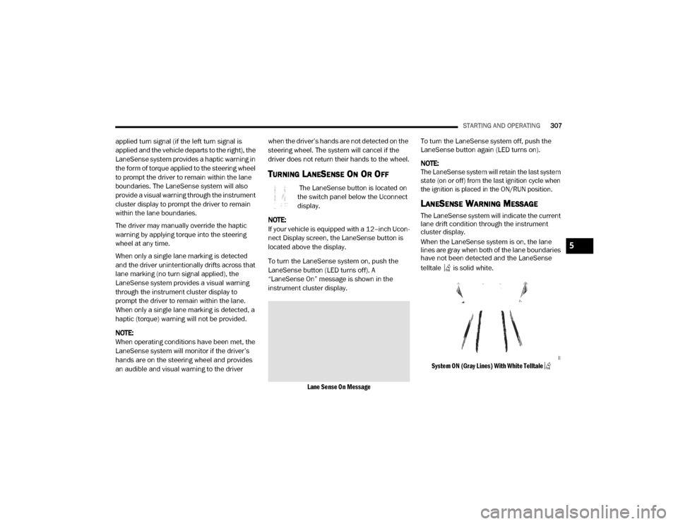
When the LaneSense system is on, the lane
lines are gray when both of the lane boundaries
have not been detected and the LaneSense
telltale is solid white.
System ON (Gray Lines) With White Telltale
5
20_DJD2_OM_EN_USC_t.book Page 307
Page 311 of 568
STARTING AND OPERATING309
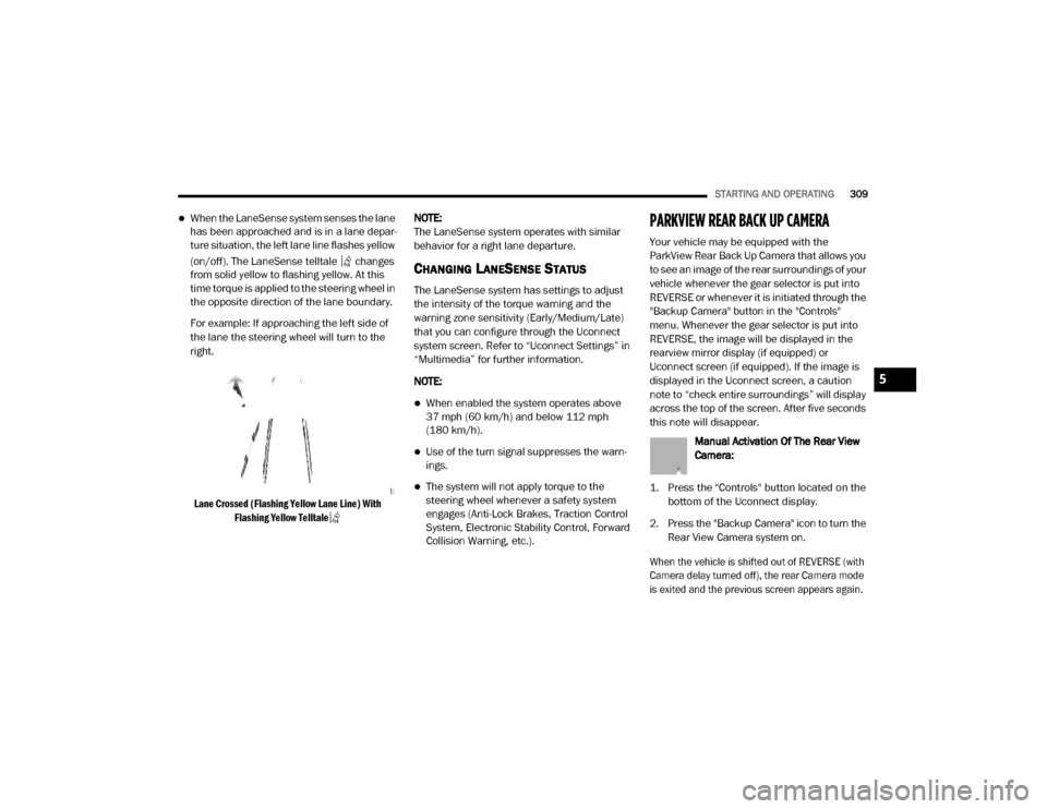
When the LaneSense system senses the lane
has been approached and is in a lane depar -
ture situation, the left lane line flashes yellow
(on/off). The LaneSense telltale changes
from solid yellow to flashing yellow. At this
time torque is applied to the steering wheel in
the opposite direction of the lane boundary.
For example: If approaching the left side of
the lane the steering wheel will turn to the
right.
Lane Crossed (Flashing Yellow Lane Line) With Flashing Yellow Telltale
NOTE:
The LaneSense system operates with similar
behavior for a right lane departure.
CHANGING LANESENSE STATUS
The LaneSense system has settings to adjust
the intensity of the torque warning and the
warning zone sensitivity (Early/Medium/Late)
that you can configure through the Uconnect
system screen. Refer to “Uconnect Settings” in
“Multimedia” for further information.
NOTE:
When enabled the system operates above
37 mph (60 km/h) and below 112 mph
(180 km/h).
Use of the turn signal suppresses the warn -
ings.
The system will not apply torque to the
steering wheel whenever a safety system
engages (Anti-Lock Brakes, Traction Control
System, Electronic Stability Control, Forward
Collision Warning, etc.).
PARKVIEW REAR BACK UP CAMERA
Your vehicle may be equipped with the
ParkView Rear Back Up Camera that allows you
to see an image of the rear surroundings of your
vehicle whenever the gear selector is put into
REVERSE or whenever it is initiated through the
"Backup Camera" button in the "Controls"
menu. Whenever the gear selector is put into
REVERSE, the image will be displayed in the
rearview mirror display (if equipped) or
Uconnect screen (if equipped). If the image is
displayed in the Uconnect screen, a caution
note to “check entire surroundings” will display
across the top of the screen. After five seconds
this note will disappear.
Manual Activation Of The Rear View
Camera:
1. Press the "Controls" button located on the bottom of the Uconnect display.
2. Press the "Backup Camera" icon to turn the Rear View Camera system on.
When the vehicle is shifted out of REVERSE (with
Camera delay turned off), the rear Camera mode
is exited and the previous screen appears again.
5
20_DJD2_OM_EN_USC_t.book Page 309
Page 336 of 568

334STARTING AND OPERATING
* The suggested selection depends and may
change depending on the customer
preferences for braking performance. Condition
of the trailer brakes, driving and road state may
also affect the selection.
Display Messages
The trailer brake control interacts with the
instrument cluster display. Display messages,
along with a single chime, will be displayed
when a malfunction is determined in the trailer
connection, trailer brake control, or on the
trailer. Refer to “Instrument Cluster Display” in
“Getting To Know Your Instrument Panel” for
further information. NOTE:
An aftermarket controller may be available
for use with trailers with air or elec
-
tric-over-hydraulic trailer brake systems. To
determine the type of brakes on your trailer
and the availability of controllers, check with
your trailer manufacturer or dealer.
Removal of the ITBM will cause errors and it
may cause damage to the electrical system
and electronic modules of the vehicle. See an
authorized dealer if an aftermarket module is
to be installed.
Towing Requirements — Trailer Lights And
Wiring
Whenever you pull a trailer, regardless of the
trailer size, stoplights and turn signals on the
trailer are required for motoring safety.
Light Electric Heavy Electric Light EOHHeavy EOH
Type of Trailer Brakes Electric Trailer Brakes Electric Trailer Brakes Electric over Hydraulic
Trailer BrakesElectric over Hydraulic
Trailer Brakes
Load *Under 10,000 lbs *Above 10,000 lbs *Under 10,000 lbs *Above 10,000 lbs
WARNING!
Connecting a trailer that is not compatible
with the ITBM system may result in reduced
or complete loss of trailer braking. There may
be a increase in stopping distance or trailer
instability which could result in personal
injury.
CAUTION!
Connecting a trailer that is not compatible
with the ITBM system may result in reduced
or complete loss of trailer braking. There may
be a increase in stopping distance or trailer
instability which could result in damage to
your vehicle, trailer, or other property.
20_DJD2_OM_EN_USC_t.book Page 334
Page 348 of 568
346
IN CASE OF EMERGENCY
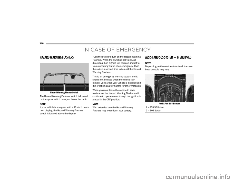
HAZARD WARNING FLASHERS
Hazard Warning Flasher Switch
The Hazard Warning Flashers switch is located
on the upper switch bank just below the radio.
NOTE:
If your vehicle is equipped with a 12–inch Ucon -
nect display, the Hazard Warning Flashers
switch is located above the display. Push the switch to turn on the Hazard Warning
Flashers. When the switch is activated, all
directional turn signals will flash on and off to
warn oncoming traffic of an emergency. Push
the switch a second time to turn off the Hazard
Warning Flashers.
This is an emergency warning system and it
should not be used when the vehicle is in
motion. Use it when your vehicle is disabled and
it is creating a safety hazard for other motorists.
When you must leave the vehicle to seek
assistance, the Hazard Warning Flashers will
continue to operate even though the ignition is
placed in the OFF position.
NOTE:
With extended use the Hazard Warning
Flashers may wear down your battery.
ASSIST AND SOS SYSTEM — IF EQUIPPED
NOTE:
Depending on the vehicles trim level, the over
-
head console may vary.
Assist And SOS Buttons
1 — ASSIST Button
2 — SOS Button
20_DJD2_OM_EN_USC_t.book Page 346
Page 351 of 568

IN CASE OF EMERGENCY349
(Continued)
SOS Call System Limitations
Vehicles sold in Mexico DO NOT have SOS Call
system capabilities. SOS or other emergency line operators in
Mexico may not answer or respond to SOS
system calls.
If the SOS Call system detects a malfunction,
any of the following may occur at the time the
malfunction is detected, and at the beginning of
each ignition cycle:
The overhead console light located between
the ASSIST and SOS buttons will continuously
be illuminated red.
The Device Screen will display the following
message: “Vehicle device requires service.
Please contact an authorized dealer.”
An In-Vehicle Audio message will state
“Vehicle device requires service. Please
contact an authorized dealer.”
Even if the SOS Call system is fully functional,
factors beyond FCA US LLC’s control may
prevent or stop the SOS Call system operation.
These include, but are not limited to, the
following factors:Delayed accessories mode is active.
The ignition is in the OFF position.
The vehicle’s electrical systems are not
intact.
The SOS Call system software and/or hard
-
ware are damaged during a crash.
The vehicle battery loses power or becomes
disconnected during a vehicle crash.
The SOS Call system is embedded into the
vehicle’s electrical system. Do not add
aftermarket electrical equipment to the
vehicle’s electrical system. This may
prevent your vehicle from sending a signal
to initiate an emergency call. To avoid inter -
ference that can cause the SOS Call system
to fail, never add aftermarket equipment
(e.g., two-way mobile radio, CB radio, data
recorder, etc.) to your vehicle’s electrical
system or modify the antennas on your
vehicle. IF YOUR VEHICLE LOSES BATTERY
POWER FOR ANY REASON (INCLUDING
DURING OR AFTER AN ACCIDENT), THE
UCONNECT FEATURES, APPS AND
SERVICES, AMONG OTHERS, WILL NOT
OPERATE.
Modifications to any part of the SOS Call
system could cause the air bag system to
fail when you need it. You could be injured
if the air bag system is not there to help
protect you.
WARNING! (Continued)
WARNING!
Ignoring the overhead console light could
mean you will not have SOS Call services. If
the overhead console light is illuminated,
have an authorized dealer service the SOS
Call system immediately.
The Occupant Restraint Control module
turns on the air bag Warning Light on the
instrument panel if a malfunction in any
part of the system is detected. If the Air Bag
Warning Light is illuminated, have an
authorized dealer service the Occupant
Restraint Control system immediately.
WARNING! (Continued)
6
20_DJD2_OM_EN_USC_t.book Page 349
Page 353 of 568

IN CASE OF EMERGENCY351
BULB REPLACEMENT
REPLACEMENT BULBS
All of the inside bulbs are brass or glass-wedge base. Aluminum base bulbs are not approved.
Interior Bulbs
Bulb Name Bulb Number
Overhead Console Lamps TS 212–9
Dome Lamp 7679
For lighted switches, see an authorized dealer for replacement instructions.
Exterior Bulbs
Bulb Name Bulb Number
Low Beam (Halogen Reflector Headlamp) H11LL
High Beam (Halogen Reflector Headlamp) 9005LL
Low & High Beam (LED Reflector Headlamp) LED (Serviced At An Authorized Dealer)
Low & High Beam (LED Projector Headlamp) LED (Serviced At An Authorized Dealer)
Turn Signal / Front Position (Halogen Reflector Headlamp) 7444NA
Turn Signal / Front Position (LED Headlamps) LED (Serviced At An Authorized Dealer)
6
20_DJD2_OM_EN_USC_t.book Page 351
Page 357 of 568

IN CASE OF EMERGENCY355
4. Reach through the access hole of the wheel
house splash shield and disengage the side
marker socket by rotating counterclockwise
a quarter turn.
Side Marker Socket
5. Pull the socket and bulb straight out from the housing.
6. Separate the bulb from the socket without twisting.
7. Reverse the procedure for installation of new bulb and covers.
Fog Lamps — If Equipped
Please see an authorized dealer for service on
LED and Halogen front fog lamps. Halogen
1. Reach under and behind the front bumper
to access the back of the front fog lamp
housing.
2. Disconnect the fog lamp wiring harness connector from the fog lamp bulb.
3. Rotate the bulb counterclockwise a quarter turn to unlock the bulb from the housing.
Fog Lamp Bulb
4. Pull the bulb straight out from the housing.
Rear Tail/Stop, Turn Signal And Backup
Lamps
1. Remove the two screws and push pins that pass through the bed sheet metal.
Tail Lamp Locations
CAUTION!
Do not contaminate the bulb glass by
touching it with your fingers or by allowing it
to contact other oily surfaces. Shortened bulb
life will result.
1 — Tail Lamp
2 — Screws
3 — Fasteners
6
20_DJD2_OM_EN_USC_t.book Page 355
Page 497 of 568

MULTIMEDIA495
Auto Unlock On Exit On Off
NOTE:
When the “Auto Unlock On Exit” feature is selected, all doors unlock when the vehicle is stopped and the transmission is in the PARK or NEUTRAL
position, and the driver's door is opened. Flash Lights With Lock On Off
NOTE:
When the “Flash Lights With Lock” feature is selected, the front and rear turn signals flash when the doors are locked or unlocked with the key fob.
This feature may be selected with or without the “Sound Horn With Lock” feature selected. Sound Horn With Lock Off1st Press 2nd Press
Sound Horn With Remote Start On Off
1st Press Of Key Fob Unlocks Driver Door All Doors
NOTE:
When “1st Press Of Key Fob Unlocks: Driver Door” is programmed, only the driver's door unlocks on the first press of the key fob Unlock button.
You must push the key fob unlock button twice to unlock the passengers’ doors.
When “All Doors” is programmed, all of the doors unlock on the first push of the key fob unlock button.
If the vehicle is programmed “1st Press Of Key Fob Unlocks: All Doors”, all doors will unlock no matter which Passive Entry equipped door handle
is grasped. If “1st Press Of Key Fob Unlocks: Driver Door” is programmed, only the driver’s door will unlock when the driver’s door is grasped.
With Passive Entry, if “1st Press Of Key Fob Unlocks: Driver Door” is programmed pushing the handle more than once only results in the driver’s
door opening. If “Driver Door” is programmed, once the driver’s door is opened, the interior door lock/unlock switch can be used to unlock all doors
(or use key fob).
Setting Name Selectable Options
9
20_DJD2_OM_EN_USC_t.book Page 495
Page 516 of 568
514MULTIMEDIA
Doors & Locks
After pressing the Doors & Locks button on the touchscreen, the following settings will be available:Flash Lights with Lock
OnOff
NOTE:
When the “Flash Lights With Lock” feature is selected, the exterior lamps flash when the doors are locked or unlocked with the key fob. This feature
may be selected with or without the “Sound Horn With Lock” feature selected. Rear Guidance Lights w/ Cargo Lights— If Equipped On
Off
NOTE:
When the “Rear Guidance Lights w/ Cargo Lights” feature is selected, the lights in the cargo and bed of the truck will come on either when the head -
light switch is pressed, or the button on the back bed of the truck is pressed.
Setting Name Selectable Options
Setting NameSelectable Options
Auto Door LocksOn Off
Auto Unlock On Exit OnOff
NOTE:
When the “Auto Unlock On Exit” feature is selected, all doors unlock when the vehicle is stopped, the transmission is in the PARK or NEUTRAL position,
and the driver's door is opened. Flash Lights With Lock OnOff
NOTE:
When the “Flash Lights With Lock” feature is selected, the front and rear turn signals flash when the doors are locked or unlocked with the key fob.
This feature may be selected with or without the “Sound Horn With Lock” feature selected. Sound Horn with Lock — If Equipped Off1st Press 2nd Press
20_DJD2_OM_EN_USC_t.book Page 514
Page 556 of 568
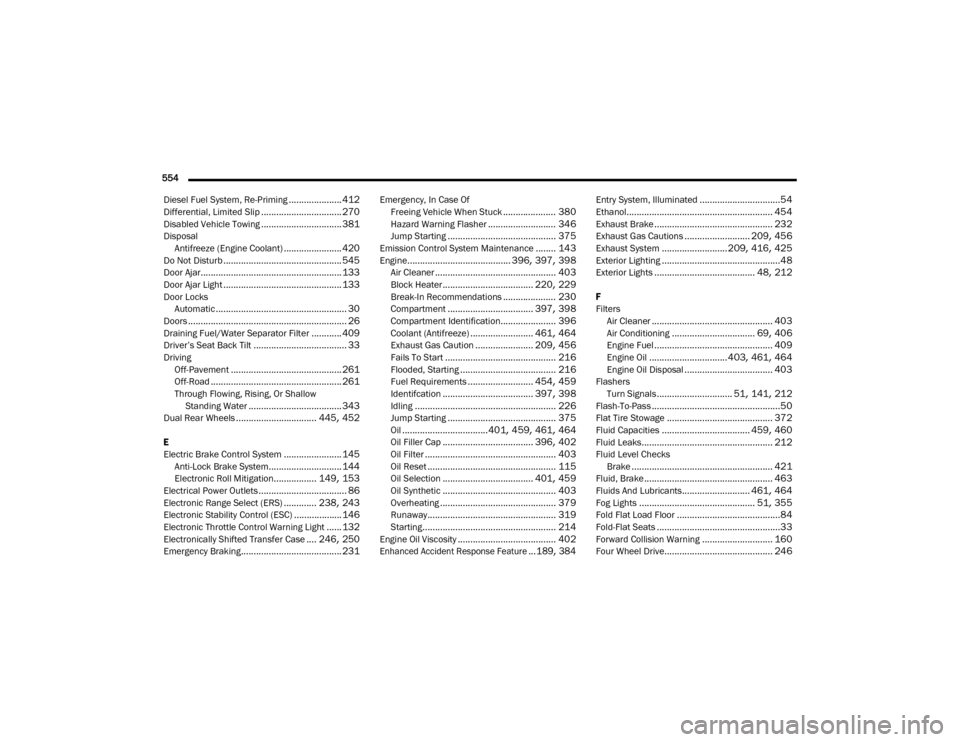
554 Diesel Fuel System, Re-Priming
..................... 412Differential, Limited Slip................................ 270Disabled Vehicle Towing................................ 381Disposal Antifreeze (Engine Coolant)....................... 420Do Not Disturb............................................... 545Door Ajar........................................................ 133Door Ajar Light............................................... 133Door LocksAutomatic.................................................... 30Doors............................................................... 26Draining Fuel/Water Separator Filter............ 409Driver’s Seat Back Tilt..................................... 33DrivingOff-Pavement............................................ 261Off-Road.................................................... 261Through Flowing, Rising, Or Shallow Standing Water..................................... 343Dual Rear Wheels................................ 445, 452
E
Electric Brake Control System....................... 145Anti-Lock Brake System............................. 144Electronic Roll Mitigation................. 149, 153Electrical Power Outlets................................... 86Electronic Range Select (ERS)............. 238, 243Electronic Stability Control (ESC)...................146Electronic Throttle Control Warning Light...... 132Electronically Shifted Transfer Case.... 246, 250Emergency Braking........................................ 231
Emergency, In Case OfFreeing Vehicle When Stuck..................... 380Hazard Warning Flasher........................... 346Jump Starting........................................... 375Emission Control System Maintenance........ 143Engine......................................... 396, 397, 398Air Cleaner................................................ 403Block Heater.................................... 220, 229Break-In Recommendations..................... 230Compartment.................................. 397, 398Compartment Identification...................... 396Coolant (Antifreeze)......................... 461, 464Exhaust Gas Caution....................... 209, 456Fails To Start............................................ 216Flooded, Starting...................................... 216Fuel Requirements.......................... 454, 459Identifcation.................................... 397, 398Idling........................................................ 226Jump Starting........................................... 375Oil..................................401, 459, 461, 464Oil Filler Cap.................................... 396, 402Oil Filter.................................................... 403Oil Reset................................................... 115Oil Selection.................................... 401, 459Oil Synthetic............................................. 403Overheating.............................................. 379Runaway................................................... 319Starting..................................................... 214Engine Oil Viscosity....................................... 402
Enhanced Accident Response Feature...189, 384
Entry System, Illuminated................................54Ethanol.......................................................... 454Exhaust Brake............................................... 232Exhaust Gas Cautions.......................... 209, 456Exhaust System..........................209, 416, 425Exterior Lighting...............................................48Exterior Lights........................................ 48, 212
F
FiltersAir Cleaner
................................................ 403Air Conditioning................................. 69, 406Engine Fuel............................................... 409Engine Oil............................... 403, 461, 464Engine Oil Disposal................................... 403FlashersTurn Signals.............................. 51, 141, 212Flash-To-Pass...................................................50Flat Tire Stowage.......................................... 372Fluid Capacities................................... 459, 460Fluid Leaks.................................................... 212Fluid Level ChecksBrake........................................................ 421Fluid, Brake................................................... 463Fluids And Lubricants........................... 461, 464Fog Lights.............................................. 51, 355Fold Flat Load Floor.........................................84Fold-Flat Seats.................................................33Forward Collision Warning............................ 160Four Wheel Drive........................................... 246
20_DJD2_OM_EN_USC_t.book Page 554