stop start Ram 3500 2020 Workshop Manual
[x] Cancel search | Manufacturer: RAM, Model Year: 2020, Model line: 3500, Model: Ram 3500 2020Pages: 568
Page 279 of 568
STARTING AND OPERATING277
In certain situations you may decide to
throw a heavy blanket or similar object over
the rope. A heavy blanket can absorb ener -
gy should the synthetic rope break. Place it
on the rope midway between the winch and
the anchor point. Do this before the rope is
put under tension. Do not approach or move
the blanket once tension is applied. Do not
allow it to get pulled into the fairlead. If it is
necessary to move or remove the blanket,
slack the tension on the rope first.
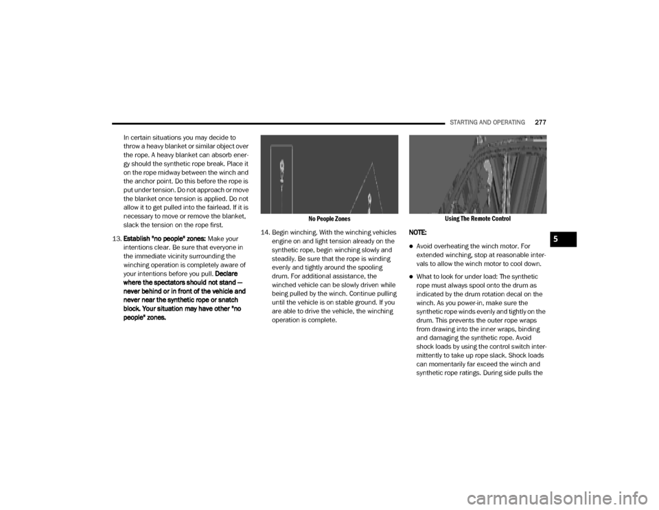
13. Establish "no people" zones: Make your
intentions clear. Be sure that everyone in
the immediate vicinity surrounding the
winching operation is completely aware of
your intentions before you pull. Declare
where the spectators should not stand —
never behind or in front of the vehicle and
never near the synthetic rope or snatch
block. Your situation may have other "no
people" zones.
No People Zones
14. Begin winching. With the winching vehicles engine on and light tension already on the
synthetic rope, begin winching slowly and
steadily. Be sure that the rope is winding
evenly and tightly around the spooling
drum. For additional assistance, the
winched vehicle can be slowly driven while
being pulled by the winch. Continue pulling
until the vehicle is on stable ground. If you
are able to drive the vehicle, the winching
operation is complete.
Using The Remote Control
NOTE:
Avoid overheating the winch motor. For
extended winching, stop at reasonable inter -
vals to allow the winch motor to cool down.
What to look for under load: The synthetic
rope must always spool onto the drum as
indicated by the drum rotation decal on the
winch. As you power-in, make sure the
synthetic rope winds evenly and tightly on the
drum. This prevents the outer rope wraps
from drawing into the inner wraps, binding
and damaging the synthetic rope. Avoid
shock loads by using the control switch inter -
mittently to take up rope slack. Shock loads
can momentarily far exceed the winch and
synthetic rope ratings. During side pulls the
5
20_DJD2_OM_EN_USC_t.book Page 277
Page 280 of 568
278STARTING AND OPERATING
synthetic rope tends to stack up at one end of
the drum. This stack can become large
enough to cause serious damage to the
winch. So, line up pulls as straight ahead as
possible and stop winching if the synthetic
rope comes close to the tie rods or mounting
plate. To fix an uneven stack, spool out that
section of the rope and reposition it to the
opposite end of the drum, which will free up
space for continued winching.
15. Secure vehicle. Once recovery of the vehicle is complete, be sure to secure the vehicle's
brakes and shift the transmission to PARK.
Release tension in the synthetic rope.
16. Disconnect the synthetic rope, and disconnect from the anchor.
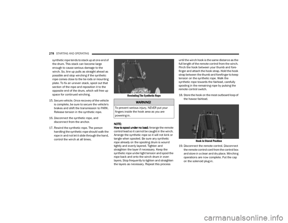
17. Rewind the synthetic rope. The person handling the synthetic rope should walk the
rope in and not let it slide through the hand,
control the winch at all times.
Rewinding The Synthetic Rope
NOTE:
How to spool under no load: Arrange the remote
control lead so it cannot be caught in the winch.
Arrange the synthetic rope so it will not kink or
tangle when spooled. Be sure any synthetic
rope already on the spooling drum is wound
tightly and evenly layered. Tighten and
straighten the layer if necessary. Keep the
synthetic rope under light tension and spool the
rope back and onto the winch drum in even
layers. Stop frequently to tighten and straighten
the layers as necessary. Repeat this process until the winch hook is the same distance as the
full length of the remote control from the winch.
Pinch the hook between your thumb and fore
-
finger and attach the hook strap. Hold the hook
strap between the thumb and forefinger to keep
tension on the synthetic rope. Walk the
synthetic rope towards the fairlead, carefully
spooling in the remaining rope by pulsing the
remote control switch.
18. Store the hook on the most outboard loop of
the hawse fairlead.
Hook In Stored Position
19. Disconnect the remote control. Disconnect the remote control cord from the control box
and store in a clean and dry place. Winching
operations are now complete. Put the cap
on the solenoid plug-in.
WARNING!
To prevent serious injury, NEVER put your
fingers inside the hook area as you are
powering-in.
20_DJD2_OM_EN_USC_t.book Page 278
Page 284 of 568

282STARTING AND OPERATING
(Continued)
The following conditions will also deactivate the
Speed Control without erasing the set speed
from memory:
Vehicle parking brake is applied
Stability event occurs
Gear selector is moved out of DRIVE
Engine overspeed occurs
ADAPTIVE CRUISE CONTROL (ACC) — IF
EQUIPPED
Adaptive Cruise Control (ACC) increases the
driving convenience provided by cruise control
while traveling on highways and major
roadways. However, it is not a safety system
and not designed to prevent collisions. Speed
Control function performs differently. Please
refer to the proper section within this chapter.
ACC will allow you to keep cruise control
engaged in light to moderate traffic conditions
without the constant need to reset your cruise
control. ACC utilizes a radar sensor and a
forward facing camera designed to detect a
vehicle directly ahead of you. NOTE:
If the sensor does not detect a vehicle ahead
of you, ACC will maintain a fixed set speed.
If the ACC sensor detects a vehicle ahead,
ACC will apply limited braking or accelerate
(not to exceed the original set speed) auto
-
matically to maintain a preset following
distance, while matching the speed of the
vehicle ahead.
The Cruise Control system has two control
modes:
Adaptive Cruise Control mode for main -
taining an appropriate distance between
vehicles.
Normal (Fixed Speed) Cruise Control mode
for cruising at a constant preset speed. For
additional information, refer to “Normal
(Fixed Speed) Cruise Control Mode” in this
section.
NOTE:
Normal (Fixed Speed) Cruise Control will not
react to preceding vehicles. Always be aware of
the mode selected. You can change the mode by using the Cruise
Control buttons. The two control modes
function differently. Always confirm which mode
is selected.
WARNING!
Adaptive Cruise Control (ACC) is a conve
-
nience system. It is not a substitute for
active driver involvement. It is always the
driver’s responsibility to be attentive of
road, traffic, and weather conditions,
vehicle speed, distance to the vehicle
ahead; and, most importantly, brake opera -
tion to ensure safe operation of the vehicle
under all road conditions. Your complete
attention is always required while driving to
maintain safe control of your vehicle.
Failure to follow these warnings can result
in a collision and death or serious personal
injury.
The ACC system:
Does not react to pedestrians,
oncoming vehicles, and stationary
objects (e.g., a stopped vehicle in a
traffic jam or a disabled vehicle).
20_DJD2_OM_EN_USC_t.book Page 282
Page 285 of 568
STARTING AND OPERATING283
(Continued)
ADAPTIVE CRUISE CONTROL (ACC)
O
PERATION
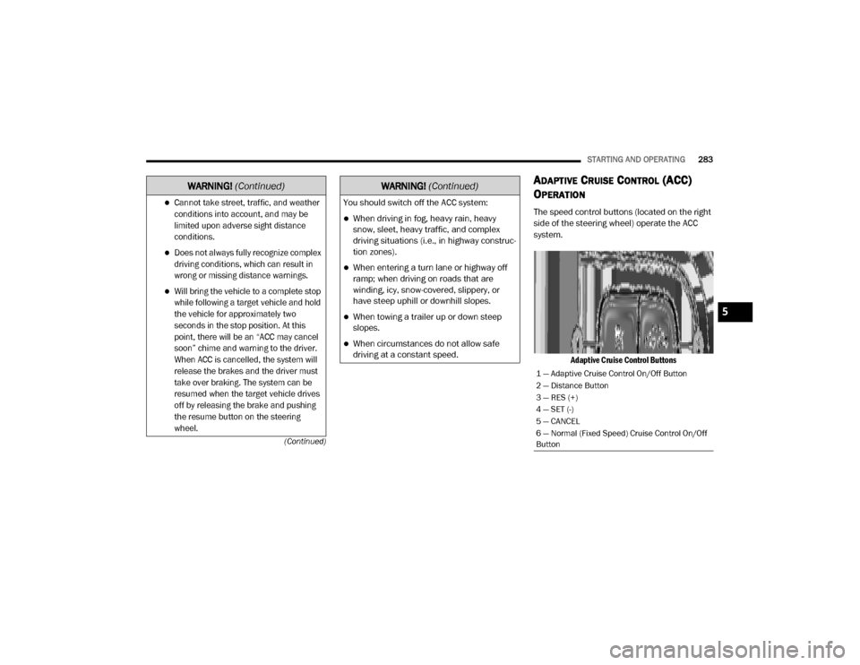
The speed control buttons (located on the right
side of the steering wheel) operate the ACC
system.
Adaptive Cruise Control ButtonsCannot take street, traffic, and weather
conditions into account, and may be
limited upon adverse sight distance
conditions.
Does not always fully recognize complex
driving conditions, which can result in
wrong or missing distance warnings.
Will bring the vehicle to a complete stop
while following a target vehicle and hold
the vehicle for approximately two
seconds in the stop position. At this
point, there will be an “ACC may cancel
soon” chime and warning to the driver.
When ACC is cancelled, the system will
release the brakes and the driver must
take over braking. The system can be
resumed when the target vehicle drives
off by releasing the brake and pushing
the resume button on the steering
wheel.
WARNING! (Continued)
You should switch off the ACC system:
When driving in fog, heavy rain, heavy
snow, sleet, heavy traffic, and complex
driving situations (i.e., in highway construc -
tion zones).
When entering a turn lane or highway off
ramp; when driving on roads that are
winding, icy, snow-covered, slippery, or
have steep uphill or downhill slopes.
When towing a trailer up or down steep
slopes.
When circumstances do not allow safe
driving at a constant speed.
WARNING! (Continued)
1 — Adaptive Cruise Control On/Off Button
2 — Distance Button
3 — RES (+)
4 — SET (-)
5 — CANCEL
6 — Normal (Fixed Speed) Cruise Control On/Off
Button
5
20_DJD2_OM_EN_USC_t.book Page 283
Page 288 of 568

286STARTING AND OPERATING
TO VARY THE SPEED SETTING
To Increase Speed
While ACC is set, you can increase the set speed
by pushing the RES (+) button.
The speed increment shown is dependent on the
chosen speed unit of U.S. (mph) or Metric (km/h):
U.S. Speed (mph)
Pushing the RES (+) button once will result in a
1 mph increase in set speed. Each subsequent
tap of the button results in an increase of 1 mph.
If the button is continually pushed, the set
speed will continue to increase in 5 mph incre -
ments until the button is released. The increase
in set speed is reflected in the instrument
cluster display.
Metric Speed (km/h)
Pushing the RES (+) button once will result in
a 1 km/h increase in set speed. Each subse -
quent tap of the button results in an increase
of 1 km/h.
If the button is continually pushed, the set
speed will continue to increase in 10 km/h
increments until the button is released. The
increase in set speed is reflected in the
instrument cluster display.
To Decrease Speed
While ACC is set, the set speed can be
decreased by pushing the SET (-) button.
The speed decrement shown is dependent on
the chosen speed unit of U.S. (mph) or Metric
(km/h):
U.S. Speed (mph)
Pushing the SET (-) button once will result in
a 1 mph decrease in set speed. Each subse -
quent tap of the button results in a decrease
of 1 mph.
If the button is continually pushed, the set
speed will continue to decrease in 5 mph
decrements until the button is released. The
decrease in set speed is reflected in the
instrument cluster display. Metric Speed (km/h)
Pushing the SET (-) button once will result in
a 1 km/h decrease in set speed. Each subse -
quent tap of the button results in a decrease
of 1 km/h.
If the button is continually pushed, the set
speed will continue to decrease in 10 km/h
decrements until the button is released. The
decrease in set speed is reflected in the
instrument cluster display.
NOTE:
When you override and push the RES (+)
button or SET (-) button, the new set speed
will be the current speed of the vehicle.
When you use the SET (-) button to decel -
erate, if the engine’s braking power does not
slow the vehicle sufficiently to reach the set
speed, the brake system will automatically
slow the vehicle.
The ACC system decelerates the vehicle to a
full stop when following a target vehicle. If an
ACC host vehicle follows a target vehicle to a
standstill, after two seconds the driver will
either have to push the RES (+) button, or
apply the accelerator pedal to reengage the
ACC to the existing set speed.
WARNING!
The Resume function should only be used if
traffic and road conditions permit. Resuming
a set speed that is too high or too low for
prevailing traffic and road conditions could
cause the vehicle to accelerate or decelerate
too sharply for safe operation. Failure to
follow these warnings can result in a collision
and death or serious personal injury.
20_DJD2_OM_EN_USC_t.book Page 286
Page 291 of 568
STARTING AND OPERATING289
ACC OPERATION AT STOP
If your ACC system brings your vehicle to a
standstill while following a vehicle ahead, your
vehicle will resume motion, without any driver
interaction, if the vehicle ahead starts moving
within two seconds.
If the target vehicle does not start moving within
two seconds of your vehicle coming to a
standstill, then ACC will cancel and the driver
must take over braking. When the target vehicle
drives off, ACC can be resumed by releasing the
brake and pushing the RES (+) button.
NOTE:
After the ACC system holds your vehicle at a
standstill for approximately two seconds, a
chime will sound and an “ACC may cancel soon”
warning will display. The brakes will release
when ACC is canceled and the driver must take
over braking.
While ACC is holding your vehicle at a standstill,
if the driver seat belt is unbuckled or the driver
door is opened, the ACC system will cancel and
the brakes will release. Driver intervention will
be required at this moment.
ADAPTIVE CRUISE CONTROL (ACC)
M
ENU
The instrument cluster display will show the
current ACC system settings. The instrument
cluster display is located in the center of the
instrument cluster. The information it displays
depends on ACC system status.
Push the Adaptive Cruise Control (ACC) on/off
button (located on the steering wheel) until one
of the following appears in the instrument
cluster display:
Adaptive Cruise Control Off
When ACC is deactivated, the display will read
“Adaptive Cruise Control Off.” Adaptive Cruise Control Ready
When ACC is activated, but the vehicle speed
setting has not been selected, the display will
read “Adaptive Cruise Control Ready.”
Adaptive Cruise Control Set
When the RES (+) or the SET(-) button (located
on the steering wheel) is pushed, the display will
read “ACC SET.”
When ACC is set, the set speed will show in the
instrument cluster display.
The ACC screen may display once again if any of
the following ACC activity occurs:
System Cancel
Driver Override
System Off
ACC Proximity Warning
ACC Unavailable Warning
The instrument cluster display will return to
the last display selected after five seconds of
no ACC display activity.
WARNING!
When the ACC system is resumed, the driver
must ensure that there are no pedestrians,
vehicles or objects in the path of the vehicle.
Failure to follow these warnings can result in
a collision and death or serious personal
injury.
5
20_DJD2_OM_EN_USC_t.book Page 289
Page 295 of 568
STARTING AND OPERATING293
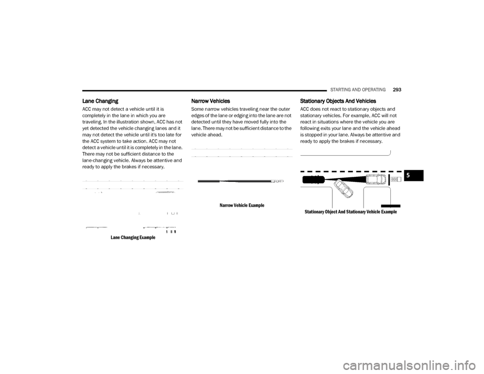
Lane Changing
ACC may not detect a vehicle until it is
completely in the lane in which you are
traveling. In the illustration shown, ACC has not
yet detected the vehicle changing lanes and it
may not detect the vehicle until it's too late for
the ACC system to take action. ACC may not
detect a vehicle until it is completely in the lane.
There may not be sufficient distance to the
lane-changing vehicle. Always be attentive and
ready to apply the brakes if necessary.
Lane Changing Example
Narrow Vehicles
Some narrow vehicles traveling near the outer
edges of the lane or edging into the lane are not
detected until they have moved fully into the
lane. There may not be sufficient distance to the
vehicle ahead.
Narrow Vehicle Example
Stationary Objects And Vehicles
ACC does not react to stationary objects and
stationary vehicles. For example, ACC will not
react in situations where the vehicle you are
following exits your lane and the vehicle ahead
is stopped in your lane. Always be attentive and
ready to apply the brakes if necessary.
Stationary Object And Stationary Vehicle Example
5
20_DJD2_OM_EN_USC_t.book Page 293
Page 303 of 568

STARTING AND OPERATING301
PARKSENSE FRONT AND REAR PARK ASSIST
The ParkSense Park Assist system provides
visual and audible indications of the distance
between the rear, and/or front fascia/bumper,
and a detected obstacle when backing up or
moving forward (e.g. during a parking
maneuver).
Refer to “ParkSense System Usage
Precautions” in this section for limitations of
this system and recommendations.
ParkSense will retain the system state (enabled
or disabled) from the previous ignition cycle
when the ignition is placed in the ON/RUN
position.
ParkSense can be active only when the gear
selector is in REVERSE or DRIVE. If ParkSense is
enabled at one of these gear selector positions,
the system will remain active until the vehicle
speed is increased to approximately 7 mph (11 km/h) or above. A warning will appear in the
instrument cluster display when the vehicle is in
REVERSE, indicating the vehicle is above
ParkSense operating speed. The system will
become active again if the vehicle speed is
decreased to speeds less than approximately
6 mph (9 km/h).
PARKSENSE SENSORS
The four ParkSense sensors, located in the rear
fascia/bumper, monitor the area behind the
vehicle that is within the sensors’ field of view.
The sensors can detect obstacles from
approximately 12 inches (30 cm) up to
79 inches (200 cm) from the rear fascia/
bumper in the horizontal direction, depending
on the location, type and orientation of the
obstacle.
NOTE:
If equipped as a dually, the ParkSense system
has six rear sensors to assist in detection
around the dually flares.
The six ParkSense sensors, located in the front
fascia/bumper, monitor the area in front of the
vehicle that is within the sensors’ field of view.
The sensors can detect obstacles from
approximately 12 inches (30 cm) up to 47 inches (120 cm) from the front fascia/
bumper in the horizontal direction, depending
on the location, type and orientation of the
obstacle.
PARKSENSE WARNING DISPLAY
The ParkSense Warning screen is located within
the instrument cluster display. It provides visual
warnings to indicate the distance between the
rear fascia/bumper and/or front fascia/bumper
and the detected obstacle. Refer to “Instrument
Cluster Display” in “Getting To Know Your
Instrument Panel” for further information.
PARKSENSE DISPLAY
The warning display will turn on indicating the
system status when the vehicle is in REVERSE
or when the vehicle is in DRIVE and an obstacle
has been detected.
The system will indicate a detected obstacle by
showing a single arc in the left and/or right rear
regions based on the obstacle’s distance and
location relative to the vehicle.
The vehicle must be driven slowly when
using ParkSense in order to be able to stop
in time when an obstacle is detected. It is
recommended that the driver looks over
his/her shoulder when using ParkSense.
CAUTION!
(Continued)
5
20_DJD2_OM_EN_USC_t.book Page 301
Page 308 of 568
306STARTING AND OPERATING
Clean the ParkSense sensors regularly,
taking care not to scratch or damage them.
The sensors must not be covered with ice,
snow, slush, mud, dirt or debris. Failure to do
so can result in the system not working prop -
erly. The ParkSense system might not detect
an obstacle behind or in front of the fascia/
bumper, or it could provide a false indication
that an obstacle is behind or in front of the
fascia/bumper.
Use the ParkSense switch to turn the Park -
Sense system off if obstacles such as bicycle
carriers, trailer hitches, etc. are placed within
18 inches (45 cm) from the rear fascia/
bumper. Failure to do so can result in the
system misinterpreting a close obstacle as a
sensor problem, causing the “Front/Rear
ParkSense Unavailable Service Required”
message to be appear in the instrument
cluster display.
On vehicles equipped with a tailgate, Park -
Sense should be disabled when the tailgate
is in the lowered or open position. A lowered
tailgate could provide a false indication that
an obstacle is behind the vehicle.
LANESENSE — IF EQUIPPED
LANESENSE OPERATION
The LaneSense system is operational at speeds
above 37 mph (60 km/h) and below 112 mph
(180 km/h). It uses a forward looking camera to
detect lane markings and measure vehicle
position within the lane boundaries.
When both lane markings are detected and the
driver unintentionally drifts out of the lane while
no turn signal has been applied OR the driver
departs the lane on the opposite side of the
WARNING!
Drivers must be careful when backing up
even when using ParkSense. Always check
carefully behind your vehicle, look behind
you, and be sure to check for pedestrians,
animals, other vehicles, obstructions, and
blind spots before backing up. You are
responsible for safety and must continue to
pay attention to your surroundings. Failure
to do so can result in serious injury or
death.
Before using ParkSense, it is strongly
recommended that the ball mount and
hitch ball assembly is disconnected from
the vehicle when the vehicle is not used for
towing. Failure to do so can result in injury
or damage to vehicles or obstacles
because the hitch ball will be much closer
to the obstacle than the rear fascia when
the loudspeaker sounds the continuous
tone. Also, the sensors could detect the ball
mount and hitch ball assembly, depending
on its size and shape, giving a false indica -
tion that an obstacle is behind the vehicle.
CAUTION!
ParkSense is only a parking aid and it is
unable to recognize every obstacle,
including small obstacles. Parking curbs
might be temporarily detected or not
detected at all. Obstacles located above or
below the sensors will not be detected
when they are in close proximity.
The vehicle must be driven slowly when
using ParkSense in order to be able to stop
in time when an obstacle is detected. It is
recommended that the driver looks over
his/her shoulder when using ParkSense.
20_DJD2_OM_EN_USC_t.book Page 306
Page 313 of 568
STARTING AND OPERATING311
The ParkView Camera is located in the center of
the tailgate handle.
NOTE:
If snow, ice, mud, or any foreign substance
builds up on the camera lens, clean the lens,
rinse with water, and dry with a soft cloth. Do
not cover the lens.
Zoom View
When the Rear View Camera image is
being displayed, and the vehicle
speed is below 8 mph (13 km/h)
while in any gear selector position,
Zoom View is available. By pressing the
“magnifying glass” icon in the upper left of the display screen, the image will zoom in to four
times the standard view. Pressing the icon a
second time will return the view to the standard
Backup Camera display.
When Zoom View is selected while the vehicle is
in REVERSE, then shifted to DRIVE, the camera
delay view will display the standard Backup
Camera view. If the vehicle is then returned to
REVERSE gear from DRIVE, the Zoom View
selection will automatically resume.
Shifting to NEUTRAL from any gear will maintain
the selected view (Zoom or Standard) as long as
the vehicle is below 8 mph (13 km/h).
If the vehicle is in PARK, Zoom View is available
until the gear selector is placed in DRIVE or
REVERSE.
NOTE:
If the vehicle is in DRIVE, NEUTRAL, or
REVERSE, and speed is greater than or equal
to 8 mph (13 km/h), Zoom View is unavail
-
able and the icon will appear gray.
While in Zoom View, the guidelines will not be
visible.
AUX CAMERA — IF EQUIPPED
Your vehicle may be equipped with one or two
AUX Cameras, which display rearview and side
view images from the trailer on the
touchscreen.
Activation
The AUX Camera is activated by first pressing
the Backup Camera, Cargo Camera (if
equipped), or Surround View Camera (if
equipped) button on the touchscreen, followed
by the AUX button located in the upper left
corner of the rearview display. The AUX camera
can also be activated when the vehicle is in
REVERSE by pressing the AUX button.
If equipped with two AUX Cameras, you can
switch between each camera by then pressing
the AUX1 or AUX2 buttons on the Trailer Camera
display.
AUX1 Camera Button
AUX2 Camera Button
CAUTION!
To avoid vehicle damage, ParkView should
only be used as a parking aid. The ParkView
camera is unable to view every obstacle or
object in your drive path.
To avoid vehicle damage, the vehicle must
be driven slowly when using ParkView to be
able to stop in time when an obstacle is
seen. It is recommended that the driver
look frequently over his/her shoulder when
using ParkView.
5
20_DJD2_OM_EN_USC_t.book Page 311