cruise control Ram 3500 2020 Owner's Manual
[x] Cancel search | Manufacturer: RAM, Model Year: 2020, Model line: 3500, Model: Ram 3500 2020Pages: 568
Page 8 of 568

6
AUTOMATIC TRANSMISSION .......................... 233Ignition Park Interlock ...............................234
Brake/Transmission Shift Interlock
System .......................................................235 Eight-Speed Automatic Transmission —
If Equipped .................................................235 Six-Speed Automatic Transmission —
If Equipped .................................................239
AUXILIARY SWITCHES — IF EQUIPPED ........... 246
ACTIVE NOISE CANCELLATION ........................ 246
FOUR-WHEEL DRIVE OPERATION —
IF EQUIPPED ...................................................... 246
Electronically Shifted Transfer Case (Eight
Speed Transmission) — If Equipped ........246 Electronically Shifted Transfer Case (Six
Speed Transmission) — If Equipped ........250 Manually Shifted Transfer Case —
If Equipped .................................................253
AIR SUSPENSION SYSTEM — IF EQUIPPED.... 256
Description .................................................256
Air Suspension Modes...............................256
Instrument Cluster Display Messages......257Operation....................................................258 AXLE LOCKER SYSTEM — POWER WAGON
MODELS ONLY (IF EQUIPPED).......................... 258
STABILIZER/SWAY BAR SYSTEM — POWER
WAGON ONLY ....................................................260
SAFE OFF-ROAD DRIVING — POWER WAGON
ONLY ...................................................................261
Off-Road Driving Tips And Vehicle
Characteristics ........................................... 261 Driving In Snow, Mud And Sand ............... 262
Crossing Obstacles (Rocks And Other
High Points) ................................................ 263 Hill Climbing ............................................... 264Driving Through Water............................... 266Airing Down For Off-Road Driving ............. 267Vehicle Recovery........................................ 268
After Driving Off-Road ................................ 270
LIMITED-SLIP DIFFERENTIAL ........................... 270
WINCH USAGE — POWER WAGON ONLY
(IF EQUIPPED) .....................................................271
Things To Know Before Using
Your Winch ................................................. 271 Understanding The Features Of
Your Winch ................................................. 271 Winch Accessories .................................... 272
Operating Your Winch ............................... 273Rigging Techniques .................................. 279 FUEL SAVER TECHNOLOGY — GAS ENGINE
(IF EQUIPPED) .................................................... 279
SPEED CONTROL .............................................. 280
To Activate.................................................. 280
To Set A Desired Speed ............................ 280To Vary The Speed Setting ........................ 280
To Accelerate For Passing ........................ 281
To Resume Speed ..................................... 281
To Deactivate ............................................. 281 ADAPTIVE CRUISE CONTROL (ACC) —
IF EQUIPPED
....................................................... 282
Adaptive Cruise Control (ACC) Operation ... 283
Activating Adaptive Cruise Control (ACC) ... 284
To Activate/Deactivate.............................. 284
To Set A Desired ACC Speed..................... 285
To Cancel ................................................... 285
To Turn Off ................................................. 285
To Resume ................................................. 285To Vary The Speed Setting ........................ 286
Setting The Following Distance In ACC .... 287
Overtake Aid............................................... 288
ACC Operation At Stop............................... 289Adaptive Cruise Control (ACC) Menu ........ 289
Display Warnings And Maintenance ........ 290
Precautions While Driving With ACC......... 291
General Information .................................. 294
Normal (Fixed Speed) Cruise Control
Mode .......................................................... 294
20_DJD2_OM_EN_USC_t.book Page 6
Page 44 of 568
42GETTING TO KNOW YOUR VEHICLE
DRIVER ADJUSTABLE PEDALS — IF
EQUIPPED
The adjustable pedals system is designed to
allow a greater range of driver comfort for
steering wheel tilt and seat position. This
feature allows the brake and accelerator pedals
to move toward or away from the driver to
provide improved position with the steering
wheel.
The adjustable pedal switch is located to the left
side of the steering column.
Adjustable Pedals Switch
The pedals can be adjusted with the ignition
OFF.
The pedals
cannot be adjusted when the
vehicle is in REVERSE or when the Speed
Control System is on. The following messages
will appear on vehicles equipped with an
instrument cluster display if the pedals are
attempted to be adjusted when the system is
locked out: “Adjustable Pedal Disabled — Cruise
Control Engaged” or “Adjustable Pedal Disabled
— Vehicle In Reverse”.
NOTE:
Always adjust the pedals to a position that
allows full pedal travel.
Further small adjustments may be necessary
to find the best possible seat/pedal position.
For vehicles equipped with Driver Memory
Settings, you can use your remote keyless
entry key fob or the memory switch on the
driver’s door trim panel to return the adjust -
able pedals to pre-programmed positions.
Refer to “Driver Memory Settings — If
Equipped” in this chapter for further informa -
tion.
MIRRORS
INSIDE DAY/NIGHT MIRROR — IF
E
QUIPPED
The mirror head can be adjusted up, down, left,
and right for various drivers. The mirror should
be adjusted to center on the view through the
rear window.
WARNING!
Do not adjust the pedals while the vehicle is
moving. You could lose control and have an
accident. Always adjust the pedals while the
vehicle is parked.
CAUTION!
Do not place any article under the adjustable
pedals or impede its ability to move, as it may
cause damage to the pedal controls. Pedal
travel may become limited if movement is
stopped by an obstruction in the adjustable
pedal's path.
20_DJD2_OM_EN_USC_t.book Page 42
Page 118 of 568

116GETTING TO KNOW YOUR INSTRUMENT PANEL
DISPLAY MENU ITEMS
Push and release the up or down arrow button
until the desired selectable menu icon is
highlighted in the instrument cluster display.
Refer to “Instrument Cluster Display” in this
chapter for further information.
Speedometer
Push and release the up or down arrow button
until the speedometer menu item is highlighted
in the instrument cluster display. Push and
release the right arrow button to cycle the
display between mph and km/h.
Vehicle Info
Push and release the up or down arrow button
until the Vehicle Info menu item is highlighted in
the instrument cluster display. Push and
release the right arrow button to enter the
submenus items of Vehicle Info. Follow the
directional prompts to access or reset any of the
following Vehicle Info submenu items:
Tire Pressure
Coolant Temperature
Transmission Temperature — If Equipped
Oil Temperature
Oil Pressure
Exhaust Brake — If Equipped
Turbo Boost — If Equipped
Oil Life
Fuel Filter Life — If Equipped
Battery Voltage
Gauge Summary
Engine Hours
Driver Assist — If Equipped
The Driver Assist menu displays the status of
the Adaptive Cruise Control (ACC) and
LaneSense systems.
Push and release the up or down arrow button
until the Driver Assist menu is displayed in the
instrument cluster display.
Adaptive Cruise Control (ACC) Feature
The instrument cluster display displays the
current ACC system settings. The information
displayed depends on ACC system status. Push the Adaptive Cruise Control (ACC) on/off
button (located on the steering wheel) until one
of the following displays in the instrument
cluster display:
Adaptive Cruise Control Off
When ACC is deactivated, the display will read
“Adaptive Cruise Control Off.”
Adaptive Cruise Control Ready
When ACC is activated but the vehicle speed
setting has not been selected, the display will
read “Adaptive Cruise Control Ready.”
Push the SET + or the SET- button (located on
the steering wheel) and the following will display
in the instrument cluster display:
ACC SET
When ACC is set, the set speed will display in
the instrument cluster.
The ACC screen may display once again if any
ACC activity occurs, which may include any of
the following:
Distance Setting Change
System Cancel
Driver Override
20_DJD2_OM_EN_USC_t.book Page 116
Page 119 of 568

GETTING TO KNOW YOUR INSTRUMENT PANEL117
System Off
ACC Proximity Warning
ACC Unavailable Warning
For further information, refer to “Adaptive
Cruise Control (ACC) — If Equipped” in “Starting
And Operating.”
LaneSense — If Equipped
The instrument cluster display displays the
current LaneSense system settings. The
information displayed depends on LaneSense
system status and the conditions that need to
be met. For further information, refer to
“LaneSense — If Equipped” in “Starting And
Operating.”
Fuel Economy
Push and release the up or down arrow button
until the Fuel Economy menu item is highlighted
in the instrument cluster display. Push and Hold
the right arrow button to reset Average Fuel
Economy.
Current Fuel Economy Gauge
Average Fuel Economy Value
Range To Empty
Trip A/Trip B
Push and release the up or down arrow button
until the Trip menu item is highlighted in the
instrument cluster display. Push and release
the right arrow button to enter the submenus of
Trip A and Trip B. The Trip A or Trip B information
will display the following:
Distance
Average Fuel Economy
Elapsed Time
Push and hold right arrow button to reset all
information.
Trailer Tow — If Equipped
Push and release the up or down arrow button
until the Trailer Tow menu item is highlighted in
the instrument cluster display. Push and
release the right arrow button and the next
screen will display the following trailer trip
information:
Trip Distance (trailer specific): Push and hold
the right arrow button to reset the distance.
Trailer Brake
Output
Type
Gain
Trailer Tire Pressure — If Equipped
Audio
Push and release the up or down arrow button
until the Audio Menu icon/title is highlighted in
the instrument cluster display. This menu will
display the audio source information, including
the Song name, Artist name, and audio source
with an accompanying graphic.
Phone Call Status
When a call is incoming, a Phone Call Status
pop-up will display on the screen. The pop-up
will remain until the phone is answered or
ignored.
NOTE:
The call status will temporarily replace the
previous media source information displayed
on the screen. When the pop-up is no longer
displayed, the display will return to the last used
screen.
3
20_DJD2_OM_EN_USC_t.book Page 117
Page 135 of 568
GETTING TO KNOW YOUR INSTRUMENT PANEL133
NOTE:
This light may turn on if the accelerator and
brake pedals are pressed at the same time.
If the light continues to flash when the vehicle is
running, immediate service is required and you
may experience reduced performance, an
elevated/rough idle, or engine stall and your
vehicle may require towing. The light will come
on when the ignition is placed in the ON/RUN or
ACC/ON/RUN position and remain on briefly as
a bulb check. If the light does not come on
during starting, have the system checked by an
authorized dealer.
Trailer Brake Disconnected Warning Light
This warning light will illuminate when
the Trailer Brake has been
disconnected.
Refer to “Trailer Towing” in “Starting And
Operating” for further information.
Transmission Temperature Warning Light
— If Equipped
This warning light will illuminate to
warn of a high transmission fluid
temperature. This may occur with
strenuous usage such as trailer towing. If this light turns on, stop the vehicle and
run the engine at idle or slightly faster, with the
transmission in PARK (P) or NEUTRAL (N), until
the light turns off. Once the light turns off, you
may continue to drive normally.
Door Open Warning Light
This indicator will illuminate when a
door is ajar/open and not fully closed.
NOTE:
If the vehicle is moving there will also be a single
chime.
YELLOW WARNING LIGHTS
Adaptive Cruise Control (ACC) Fault
Warning Light — If Equipped
This warning light will illuminate to
indicate a fault in the ACC system.
Contact a local authorized dealer for
service.
For further information, refer to “Adaptive
Cruise Control (ACC)” in “Starting And
Operating.”
Air Suspension Fault Warning Light — If
Equipped
This light will illuminate when a fault is
detected with the air suspension
system.
Refer to “Air Suspension System — If Equipped”
in “Starting And Operating” for further
information.
Engine Check/Malfunction Indicator
Warning Light (MIL)
The Engine Check/Malfunction
Indicator Light (MIL) is a part of an
Onboard Diagnostic System called
OBD II that monitors engine and
WARNING!
If you continue operating the vehicle when
the Transmission Temperature Warning Light
is illuminated you could cause the fluid to boil
over, come in contact with hot engine or
exhaust components and cause a fire.
CAUTION!
Continuous driving with the Transmission
Temperature Warning Light illuminated will
eventually cause severe transmission
damage or transmission failure.
3
20_DJD2_OM_EN_USC_t.book Page 133
Page 142 of 568

140GETTING TO KNOW YOUR INSTRUMENT PANEL
Low Diesel Exhaust Fluid (DEF) Indicator
Light — If Equipped
The Low Diesel Exhaust Fluid (DEF)
Indicator will illuminate if the vehicle
is low on Diesel Exhaust Fluid (DEF).
Refer to “Starting And Operating” for
further information.
Wait To Start Light — If Equipped
This indicator light will illuminate for
approximately two seconds when the
ignition is turned to the RUN position.
Its duration may be longer based on
colder operating conditions. Vehicle will not
initiate start until telltale is no longer displayed.
Refer to “Starting The Engine” in “Starting And
Operating” for further information.
NOTE:
The “Wait To Start” telltale may not illuminate if
the intake manifold temperature is warm
enough.
Water In Fuel Indicator Light — If Equipped
The “Water In Fuel Indicator Light” will
illuminate when there is water
detected in the fuel filter. If this light
remains on, DO NOT start the vehicle before you drain the water from the fuel filter to
prevent engine damage.
Refer to the “Draining Fuel/Water Separator
Filter” section in “Dealer Service” in “Servicing
And Maintenance” for further information.
GREEN INDICATOR LIGHTS
Adaptive Cruise Control (ACC) Set With
Target Light — If Equipped
This will display when the ACC is set
and a target vehicle is detected.
Refer to “Adaptive Cruise Control
(ACC) — If Equipped” in “Starting And Operating”
for further information.
Adaptive Cruise Control (ACC) Set With No
Target Detected Indicator Light — If
Equipped
This light will turn on when the
Adaptive Cruise Control is SET and
there is no target vehicle detected.
Refer to "Adaptive Cruise Control (ACC) — If
Equipped" in "Starting And Operating" for
further information.
Automatic Diesel Exhaust Brake Indicator
Light — If Equipped
This indicator light will illuminate
when the Diesel Exhaust Brake has
been activated, and has switched to
Automatic mode.
Refer to “Diesel Exhaust Brake — Engine
Braking (If Equippes)” in “Starting And
Operating” for further information.
ECO Mode Indicator Light
This light will turn on when ECO Mode
is active.
Park/Headlight On Indicator Light
This indicator light will illuminate
when the park lights or headlights are
turned on.
Refer to “Exterior Lights” in “Getting To Know
Your Vehicle” for further information.
LaneSense Indicator Light — If Equipped
The LaneSense indicator light
illuminates solid green when both
lane markings have been detected
and the system is “armed” and ready
20_DJD2_OM_EN_USC_t.book Page 140
Page 143 of 568
GETTING TO KNOW YOUR INSTRUMENT PANEL141
to provide visual and torque warnings if an
unintentional lane departure occurs.
Refer to “LaneSense — If Equipped” in “Starting
And Operating” for further information.
Front Fog Indicator Light — If Equipped
This indicator light will illuminate
when the front fog lights are on.
Refer to “Exterior Lights” in “Getting
To Know Your Vehicle” for further information.
Turn Signal Indicator Lights
When the left or right turn signal is
activated, the turn signal indicator will
flash independently and the
corresponding exterior turn signal
lamps will flash. Turn signals can be activated
when the multifunction lever is moved down
(left) or up (right).
NOTE:
A continuous chime will sound if the vehicle is
driven more than 1 mile (1.6 km) with either
turn signal on.
Check for an inoperative outside light bulb if
either indicator flashes at a rapid rate.
If equipped with fog lamps, the fog lamp on the
side of the activated turn signal will also illumi -
nate to provide additional light when turning.
Cruise Control Set Indicator Light — If
Equipped
This indicator light will illuminate
when the cruise control is set to the
desired speed. Refer to “Speed
Control” in “Starting And Operating”
for further information.
WHITE INDICATOR LIGHTS
Adaptive Cruise Control (ACC) Ready Light
— If Equipped
This light will illuminate when the vehicle
equipped with Adaptive Cruise Control
(ACC) has been turned on but not set.
Refer to “Adaptive Cruise Control (ACC) — If
Equipped” in “Starting And Operating” for
further information.
Cruise Control Ready Indicator
This indicator light will illuminate
when the cruise control is ready,
but not set. Refer to “Speed Control”
in “Starting And Operating” for
further information.
Hill Descent Control (HDC) Indicator Light
— If Equipped
This indicator shows when the Hill
Descent Control (HDC) feature is
turned on. The lamp will be on solid
when HDC is armed. HDC can only be
armed when the transfer case is in the “4WD
LOW” position and the vehicle speed is less
then 20 mph (32 km/h). If these conditions are
not met while attempting to use the HDC
feature, the HDC indicator light will flash on/off.
LaneSense Indicator Light — If Equipped
When the LaneSense system is ON,
but not armed, the LaneSense
indicator light illuminates solid white.
This occurs when only left, right, or
neither lane line has been detected. If a single
lane line is detected, the system is ready to
provide only visual warnings if an unintentional
lane departure occurs on the detected lane line.
Refer to “LaneSense — If Equipped” in “Starting
And Operating” for further information.
3
20_DJD2_OM_EN_USC_t.book Page 141
Page 281 of 568

STARTING AND OPERATING279
NOTE:
Always store the remote control in a protected,
clean, dry area.
RIGGING TECHNIQUES
Various winching situations will require
application of other winching techniques. These
could range from too little distance to achieve
maximum pull using straight line rigging, simply
increasing pulling power, or maintaining a
straight-line pulling situation. You will have to
assess what technique is correct for your
situation. Think "safety" at all times.
How To Change The Pulling Direction
Change Pulling Directions
All winching operations should have a straight
line from the winch to the object being pulled. This minimizes the synthetic rope collecting on
one side of the drum affecting pulling efficiency
and damaging synthetic rope. A snatch block,
secured to a point directly in front of the vehicle
will enable you to change your pulling direction
while still allowing the synthetic rope to be at
90° to wind properly onto the spooling drum.
Increasing Pulling Power
In some cases, you may find yourself needing
more pulling power. The use of snatch blocks
increases mechanical advantage and that
increases your pulling power.
Double Line
Wire Rope Routing
Because pulling power decreases with the
number of layers of synthetic rope on the winch drum, you can use a snatch block to double line
out more rope. This decreases the number of
layers of synthetic rope on the drum, and
increases pulling power. Start by feeding out
enough synthetic rope to free the winch hook.
Attach the hook to your vehicle's frame/tow
hook and run the rope through a snatch block.
Disengage the clutch and, using the snatch
block, pull out enough synthetic rope to reach
your anchor point. Do not attach the hook to the
mounting kit. Secure to the anchor point with a
tree trunk protector or choker chain. Attach the
clevis/shackle. Attach the shackle to the two
ends of the strap/chain, being careful not to
over tighten (tighten and back-off 1/2 turn).
FUEL SAVER TECHNOLOGY — GAS ENGINE
(IF EQUIPPED)
This feature offers improved fuel economy by
shutting off four of the engine's eight cylinders
during light load and cruise conditions. The
system is automatic with no driver inputs or
additional driving skills required.
NOTE:
This system may take some time to return to full
functionality after a battery disconnect.
5
20_DJD2_OM_EN_USC_t.book Page 279
Page 282 of 568
280STARTING AND OPERATING
SPEED CONTROL
When engaged, the Speed Control takes over
accelerator operations at speeds greater than
20 mph (32 km/h), or 25 mph (40 km/h),
depending on the powertrain used.
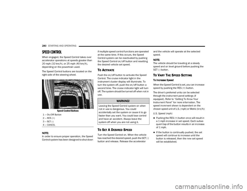
The Speed Control buttons are located on the
right side of the steering wheel.
Speed Control Buttons
NOTE:
In order to ensure proper operation, the Speed
Control system has been designed to shut down if multiple speed control functions are operated
at the same time. If this occurs, the Speed
Control system can be reactivated by pushing
the Speed Control on/off button and resetting
the desired vehicle set speed.
TO ACTIVATE
Push the on/off button to activate the Speed
Control. The cruise indicator light in the
instrument cluster display will illuminate. To
turn the system off, push the on/off button a
second time. The cruise indicator light will turn
off. The system should be turned off when not in
use.
TO SET A DESIRED SPEED
Turn the Speed Control on. When the vehicle
has reached the desired speed, push the SET (-)
button and release. Release the accelerator and the vehicle will operate at the selected
speed.
NOTE:
The vehicle should be traveling at a steady
speed and on level ground before pushing the
SET (-) button.
TO VARY THE SPEED SETTING
To Increase Speed
When the Speed Control is set, you can increase
speed by pushing the RES (+) button.
The driver’s preferred units can be selected
through the instrument panel settings (if
equipped). Refer to “Getting To Know Your
Instrument Panel” for more information. The
speed increment shown is dependent on the
chosen speed unit of U.S. (mph) or Metric (km/h):
U.S. Speed (mph)
Pushing the RES (+) button once will result in
a 1 mph increase in set speed. Each subse -
quent tap of the button results in an increase
of 1 mph.
If the button is continually pushed, the set
speed will continue to increase until the
button is released, then the new set speed
will be established.
1 — On/Off Button
2 — RES (+)
3 — SET (-)
4 — CANCEL
WARNING!
Leaving the Speed Control system on when
not in use is dangerous. You could
accidentally set the system or cause it to go
faster than you want. You could lose control
and have an accident. Always leave the
system off when you are not using it.
20_DJD2_OM_EN_USC_t.book Page 280
Page 284 of 568
282STARTING AND OPERATING
(Continued)
The following conditions will also deactivate the
Speed Control without erasing the set speed
from memory:
Vehicle parking brake is applied
Stability event occurs
Gear selector is moved out of DRIVE
Engine overspeed occurs
ADAPTIVE CRUISE CONTROL (ACC) — IF
EQUIPPED
Adaptive Cruise Control (ACC) increases the
driving convenience provided by cruise control
while traveling on highways and major
roadways. However, it is not a safety system
and not designed to prevent collisions. Speed
Control function performs differently. Please
refer to the proper section within this chapter.
ACC will allow you to keep cruise control
engaged in light to moderate traffic conditions
without the constant need to reset your cruise
control. ACC utilizes a radar sensor and a
forward facing camera designed to detect a
vehicle directly ahead of you. NOTE:
If the sensor does not detect a vehicle ahead
of you, ACC will maintain a fixed set speed.
If the ACC sensor detects a vehicle ahead,
ACC will apply limited braking or accelerate
(not to exceed the original set speed) auto
-
matically to maintain a preset following
distance, while matching the speed of the
vehicle ahead.
The Cruise Control system has two control
modes:
Adaptive Cruise Control mode for main -
taining an appropriate distance between
vehicles.
Normal (Fixed Speed) Cruise Control mode
for cruising at a constant preset speed. For
additional information, refer to “Normal
(Fixed Speed) Cruise Control Mode” in this
section.
NOTE:
Normal (Fixed Speed) Cruise Control will not
react to preceding vehicles. Always be aware of
the mode selected. You can change the mode by using the Cruise
Control buttons. The two control modes
function differently. Always confirm which mode
is selected.
WARNING!
Adaptive Cruise Control (ACC) is a conve
-
nience system. It is not a substitute for
active driver involvement. It is always the
driver’s responsibility to be attentive of
road, traffic, and weather conditions,
vehicle speed, distance to the vehicle
ahead; and, most importantly, brake opera -
tion to ensure safe operation of the vehicle
under all road conditions. Your complete
attention is always required while driving to
maintain safe control of your vehicle.
Failure to follow these warnings can result
in a collision and death or serious personal
injury.
The ACC system:
Does not react to pedestrians,
oncoming vehicles, and stationary
objects (e.g., a stopped vehicle in a
traffic jam or a disabled vehicle).
20_DJD2_OM_EN_USC_t.book Page 282