remote control Ram 3500 2020 Owner's Manual
[x] Cancel search | Manufacturer: RAM, Model Year: 2020, Model line: 3500, Model: Ram 3500 2020Pages: 568
Page 6 of 568

4
GARAGE DOOR OPENER — IF EQUIPPED .........76 Before You Begin Programming
HomeLink® .................................................. 76 Canadian/Gate Operator Programming ..... 79
Using HomeLink® ........................................ 79
Security......................................................... 80
Troubleshooting Tips ................................... 80
General Information .................................... 80
INTERNAL EQUIPMENT ........................................81
Storage ......................................................... 81
Cupholders .................................................. 86
Electrical Power Outlets .............................. 86
Power Inverter — If Equipped ..................... 88
Wireless Charging Pad — If Equipped ........ 89
Overhead Sunglass Storage........................ 90
PICKUP BOX .........................................................90
Cargo Camera — If Equipped ...................... 91
RAMBOX — IF EQUIPPED .....................................92
RamBox Integrated Box Side
Storage Bins ................................................. 92 RamBox Safety Warning .............................. 94
Bed Divider — If Equipped ........................... 94
Bed Rail Tie-Down System — If Equipped .. 96
SLIDE-IN CAMPERS .............................................98
Camper Applications ................................... 98 EASY-OFF TAILGATE ........................................... 98
Disconnecting The Rear Camera And
Remote Keyless Entry ................................. 98 Removing The Tailgate ................................ 99
Locking Tailgate ........................................... 99
TRI-FOLD TONNEAU COVER — IF EQUIPPED ..100
Tri-Fold Tonneau Cover Removal.............. 100
Tri-Fold Tonneau Cover Installation.......... 102Tri-Fold Tonneau Cover Cleaning .............. 105
GETTING TO KNOW YOUR
INSTRUMENT PANEL
BASE / MIDLINE INSTRUMENT CLUSTER —
GAS ENGINE........................................................ 106
Base / Midline Instrument Cluster
Descriptions — Gas Engine ....................... 106
PREMIUM INSTRUMENT CLUSTER —
GAS ENGINE........................................................ 108
Premium Instrument Cluster
Descriptions — Gas Engine ....................... 108
BASE INSTRUMENT CLUSTER —
DIESEL ENGINE ................................................. 110
Base Instrument Cluster Descriptions —
Diesel Engine ............................................. 110 PREMIUM INSTRUMENT CLUSTER —
DIESEL ENGINE .................................................. 112
Premium Instrument Cluster
Descriptions — Diesel Engine ................... 112
INSTRUMENT CLUSTER DISPLAY ................... 113
Instrument Cluster Display Controls ........ 114
Oil Life Reset ............................................. 115
Display Menu Items ................................... 116
Diesel Messages And Warnings — 6.7L
Cummins Diesel Engine ............................ 125 Battery Saver On/Battery Saver Mode
Message — Electrical Load Reduction
Actions — If Equipped ............................... 129
WARNING LIGHTS AND MESSAGES ............... 130
Red Warning Lights ................................... 130
Yellow Warning Lights ............................... 133Yellow Indicator Lights .............................. 138
Green Indicator Lights ............................... 140White Indicator Lights ............................... 141Blue Indicator Lights ................................. 142
ONBOARD DIAGNOSTIC SYSTEM — OBD II ... 142
Onboard Diagnostic System
(OBD II) Cybersecurity ............................... 142
EMISSIONS INSPECTION AND MAINTENANCE
PROGRAMS ....................................................... 143
20_DJD2_OM_EN_USC_t.book Page 4
Page 17 of 568

GETTING TO KNOW YOUR VEHICLE15
The turn signal lights will flash to acknowledge the
unlock signal. The illuminated entry system will
also turn on.
NOTE:
All doors can be programmed to unlock on the
first push of the unlock button. Refer to “Ucon -
nect Settings” in “Multimedia” for further infor -
mation.
To Lock The Doors And Tailgate
Push and release the lock button on the key fob
to lock all doors, the tailgate, and the RamBox
(if equipped). The turn signal lights will flash and
the horn will chirp to acknowledge the signal.
Sound Horn With Remote Key Lock — If
Equipped
This feature will cause the horn to chirp when
the doors are locked with the key fob. This
feature can be turned on or turned off through
the Uconnect Settings. NOTE:
Pushing the lock button on the key fob while you
are in the vehicle will activate the vehicle secu
-
rity alarm system. Opening a door with the
vehicle security alarm system activated will
cause the alarm to sound. Push the unlock
button to deactivate the vehicle security alarm
system.
Refer to “Vehicle Security Alarm” in this chapter
for further information.
Using The Panic Alarm
To turn the Panic Alarm feature on or off, push
the Panic button on the key fob. When the Panic
Alarm is activated, the turn signals will flash, the
horn will pulse on and off, and the interior lights
will turn on.
The Panic Alarm will stay on for three minutes
unless you turn it off by either pushing the Panic
button a second time or drive the vehicle at a
speed of 15 mph (24 km/h) or greater. NOTE:
The interior lights will turn off if you place the
ignition in the ACC or ON/RUN position while
the Panic Alarm is activated. However, the
exterior lights and horn will remain on.
You may need to be less than 35 ft (11 m)
from the vehicle when using the key fob to
turn off the Panic Alarm due to the radio
frequency noises emitted by the system.
Replacing The Battery In The Key Fob With
Remote Control
The replacement battery model is one CR2450
battery.
NOTE:
Perchlorate Material — special handling may
apply. See www.dtsc.ca.gov/hazard
-
ouswaste/perchlorate for further informa -
tion.
Do not touch the battery terminals that are
on the back housing or the printed circuit
board.
2
20_DJD2_OM_EN_USC_t.book Page 15
Page 20 of 568
18GETTING TO KNOW YOUR VEHICLE
(Continued)
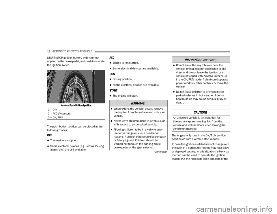
START/STOP ignition button, with your foot
applied on the brake pedal, and push to operate
the ignition switch.
Keyless Push Button Ignition
The push button ignition can be placed in the
following modes:
OFF
The engine is stopped.
Some electrical devices (e.g. Central locking,
alarm, etc.) are still available. ACC
Engine is not started.
Some electrical devices are available.
RUN
Driving position.
All the electrical devices are available.
START
The engine will start.
The engine only runs in the ON/RUN ignition
position or from a remote start request.
In case the ignition switch does not change with
the push of a button, the key fob may have a low
or depleted battery. In this situation, a back up
method can be used to operate the ignition
switch. Put the nose side (side opposite of the
1 — OFF
2 — ACC (Accessory)
3 — ON/RUN
WARNING!
When exiting the vehicle, always remove
the key fob from the vehicle and lock your
vehicle.
Never leave children alone in a vehicle, or
with access to an unlocked vehicle.
Allowing children to be in a vehicle unat-
tended is dangerous for a number of
reasons. A child or others could be seriously
or fatally injured. Children should be
warned not to touch the parking brake,
brake pedal or the gear selector.
Do not leave the key fob in or near the
vehicle, or in a location accessible to chil -
dren, and do not leave the ignition of a
vehicle equipped with Keyless Enter-N-Go
in the ON/RUN mode. A child could operate
power windows, other controls, or move the
vehicle.
Do not leave children or animals inside
parked vehicles in hot weather. Interior
heat build-up may cause serious injury or
death.
CAUTION!
An unlocked vehicle is an invitation for
thieves. Always remove key fob from the
vehicle and lock all doors when leaving the
vehicle unattended.
WARNING! (Continued)
20_DJD2_OM_EN_USC_t.book Page 18
Page 21 of 568
GETTING TO KNOW YOUR VEHICLE19
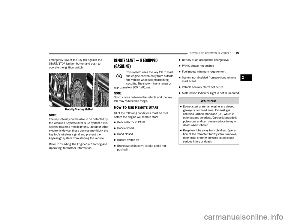
emergency key) of the key fob against the
START/STOP ignition button and push to
operate the ignition switch.
Back Up Starting Method
NOTE:
The key fob may not be able to be detected by
the vehicle’s Keyless Enter-N-Go system if it is
located next to a mobile phone, laptop or other
electronic device; these devices may block the
key fob’s wireless signal and prevent the
keyless-go system from starting the vehicle.
Refer to "Starting The Engine" in "Starting And
Operating" for further information.REMOTE START — IF EQUIPPED
(GASOLINE)
This system uses the key fob to start
the engine conveniently from outside
the vehicle while still maintaining
security. The system has a range of
approximately 300 ft (91 m).
NOTE:
Obstructions between the vehicle and the key
fob may reduce this range.
HOW TO USE REMOTE START
All of the following conditions must be met
before the engine will remote start:
Gear selector in PARK
Doors closed
Hood closed
Hazard switch off
Brake switch inactive (brake pedal not
pushed)
Battery at an acceptable charge level
PANIC button not pushed
Fuel meets minimum requirement
System not disabled from previous remote
start event
Vehicle security alarm not active
Malfunction Indicator Light is not illuminated
WARNING!
Do not start or run an engine in a closed
garage or confined area. Exhaust gas
contains Carbon Monoxide (CO) which is
odorless and colorless. Carbon Monoxide is
poisonous and can cause serious injury or
death when inhaled.
Keep key fobs away from children. Opera -
tion of the Remote Start System, windows,
door locks or other controls could cause
serious injury or death.
2
20_DJD2_OM_EN_USC_t.book Page 19
Page 24 of 568
22GETTING TO KNOW YOUR VEHICLE
HOW TO USE REMOTE START
All of the following conditions must be met
before the engine will remote start:
Transmission in PARK
Doors closed
Hood closed
Hazard switch off
Brake switch inactive (brake pedal not
pushed)
Battery at an acceptable charge level
PANIC button not pushed
Fuel meets minimum requirement
Water In Fuel Indicator Light is not illumi -
nated
Wait To Start Light Indicator Light is not illu -
minated
Malfunction Indicator Light is not illuminated
REMOTE START ABORT MESSAGE
The following messages will display in the
instrument cluster display if the vehicle fails to
remote start or exits remote start prematurely:
Remote Start Aborted — Door Open
Remote Start Aborted — Hood Open
Remote Start Aborted — Fuel Low
Remote Start Aborted — System Fault
The instrument cluster display message is
stored until the ignition is placed in the ON/RUN
position.
TO ENTER REMOTE START MODE
Push and release the Remote Start button on
the key fob twice, within five seconds. The
parking lights will flash and the horn will chirp
twice (if programmed). In cold ambient
temperature conditions, the diesel vehicle may
delay crank up to 30 seconds for the Intake Air
Heater. Once the vehicle has started, the
engine will run for 15 minutes.
NOTE:
Crank may be delayed up to 75 seconds for
intake air heater operation at high altitudes,
and/or extreme cold.
The park lamps will turn on and remain on
during Remote Start mode.
For security, power window and power sunroof
operation (if equipped) are disabled when the
vehicle is in the Remote Start mode.
Additional features, such as windshield
wipers, will also not be available while the
vehicle is in the Remote Start mode.
The engine can be started two consecutive
times (two 15 minute cycles) with the key fob.
However, the ignition switch must be placed in
the ON/RUN position before you can repeat
the start sequence for a third cycle.
WARNING!
Do not start or run an engine in a closed
garage or confined area. Exhaust gas
contains Carbon Monoxide (CO) which is
odorless and colorless. Carbon Monoxide is
poisonous and can cause serious injury or
death when inhaled.
Keep key fobs away from children. Opera -
tion of the Remote Start System, windows,
door locks or other controls could cause
serious injury or death.
20_DJD2_OM_EN_USC_t.book Page 22
Page 39 of 568
GETTING TO KNOW YOUR VEHICLE37
HEATED SEATS — IF EQUIPPED
On some models, the front and rear seats may
be equipped with heaters located in the seat
cushions and seat backs.
Front Heated Seats
The heated seats control buttons are located on
the center instrument panel below the
touchscreen, and are also located within the
climate or controls screen of the touchscreen.
NOTE:
If the vehicle is equipped with a 12-inch radio,
there will only be control buttons through the
touchscreen.
Push the heated seat buttononce to turn the
HI setting on.
Push the heated seat button a second time to
turn the MED setting on.
Push the heated seat button a third time to
turn the LO setting on.
Push the heated seat buttona fourth time to
turn the heating elements off.
NOTE:
The engine must be running for the heated
seats to operate.
The level of heat selected will stay on until
the operator changes it. Vehicles Equipped With Remote Start
On models that are equipped with remote start,
the driver’s seat can be programmed to come
on during a remote start.
This feature can be programmed through the
Uconnect system. Refer to “Uconnect Settings”
in “Multimedia” for further information.
Rear Heated Seats
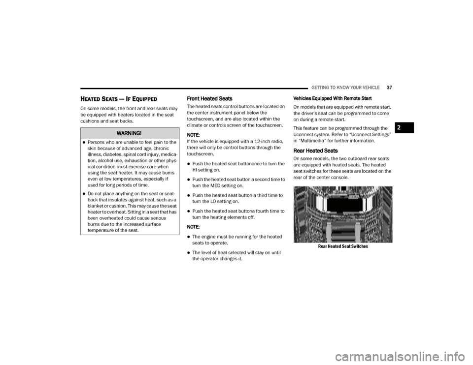
On some models, the two outboard rear seats
are equipped with heated seats. The heated
seat switches for these seats are located on the
rear of the center console.
Rear Heated Seat Switches
WARNING!
Persons who are unable to feel pain to the
skin because of advanced age, chronic
illness, diabetes, spinal cord injury, medica -
tion, alcohol use, exhaustion or other phys -
ical condition must exercise care when
using the seat heater. It may cause burns
even at low temperatures, especially if
used for long periods of time.
Do not place anything on the seat or seat -
back that insulates against heat, such as a
blanket or cushion. This may cause the seat
heater to overheat. Sitting in a seat that has
been overheated could cause serious
burns due to the increased surface
temperature of the seat.
2
20_DJD2_OM_EN_USC_t.book Page 37
Page 40 of 568

38GETTING TO KNOW YOUR VEHICLE
There are two heated seat switches that allow
the rear passengers to operate the seats
independently. You can choose from HI, MED,
LO, or OFF heat settings. Amber indicator lights
in each switch indicate the level of heat in use.
Push the heated seat buttononce to turn the
HI setting on.
Push the heated seat button a second time to
turn the MED setting on.
Push the heated seat button a third time to
turn the LO setting on.
Push the heated seat buttona fourth time to
turn the heating elements off.
NOTE:
The level of heat selected will stay on until
the operator changes it.
Once a heat setting is selected, heat will be
felt within two to five minutes.
The engine must be running for the heated
seats to operate.
VENTILATED SEATS — IF EQUIPPED
Front Ventilated Seats
Located in the seat cushion are small fans that
draw the air from the passenger compartment
and move air through fine perforations in the
seat cover to help keep the driver and front
passenger cooler in higher ambient
temperatures. The fans operate at three
speeds, HI, MED and LO.
The front ventilated seats control buttons are
located on the center instrument panel below
the touchscreen, and are also located within the
climate or controls screen of the touchscreen.
NOTE:
If the vehicle is equipped with a 12-inch radio,
there will only be control buttons through the
touchscreen.
Press the ventilated seat button once to
choose HI.
Press the ventilated seat button a second
time to choose MED.
Press the ventilated seat button a third time
to choose LO.
Press the ventilated seat button a fourth time
to turn the ventilation off.
NOTE:
The engine must be running for the ventilated
seats to operate.
Vehicles Equipped With Remote Start
On models that are equipped with remote start,
the driver’s seat can be programmed to come
on during a remote start.
This feature can be programmed through the
Uconnect system. Refer to “Uconnect Settings”
in “Multimedia” for further information.
HEAD RESTRAINTS
Head restraints are designed to reduce the risk
of injury by restricting head movement in the
event of a rear impact. Head restraints should
be adjusted so that the top of the head restraint
is located above the top of your ear.
20_DJD2_OM_EN_USC_t.book Page 38
Page 43 of 568
GETTING TO KNOW YOUR VEHICLE41
STEERING WHEEL
TILT STEERING COLUMN
This feature allows you to tilt the steering
column upward or downward. The tilt lever is
located on the steering column, below the
multifunction lever.
Pull the lever toward the steering wheel to
unlock the steering column. With one hand
firmly on the steering wheel, move the steering
column up or down, as desired. Release the
lever to lock the steering column firmly in place.
Tilt Steering Lever
HEATED STEERING WHEEL — IF
E
QUIPPED
The steering wheel contains a heating element
that helps warm your hands in cold weather.
The heated steering wheel has only one
temperature setting. Once the heated steering
wheel has been turned on, it will stay on until
the operator turns it off. The heated steering
wheel may not turn on when it is already warm.
The heated steering wheel control button is
located on the center instrument panel below
the touchscreen, as well as within the climate or
controls screen of the touchscreen.
Press the heated steering wheel button once
to turn the heating element on.
Press the heated steering wheel button a
second time to turn the heating element off. NOTE:
The engine must be running for the heated
steering wheel to operate.
Vehicles Equipped With Remote Start
On models that are equipped with remote start,
the heated steering wheel can be programmed
to come on during a remote start.
This feature can be programmed through the
Uconnect system. Refer to “Uconnect Settings”
in “Multimedia” for further information.
WARNING!
Do not adjust the steering column while
driving. Adjusting the steering column while
driving or driving with the steering column
unlocked, could cause the driver to lose
control of the vehicle. Failure to follow this
warning may result in serious injury or death.
WARNING!
Persons who are unable to feel pain to the
skin because of advanced age, chronic
illness, diabetes, spinal cord injury, medica
-
tion, alcohol use, exhaustion, or other phys -
ical conditions must exercise care when
using the steering wheel heater. It may
cause burns even at low temperatures,
especially if used for long periods.
Do not place anything on the steering wheel
that insulates against heat, such as a
blanket or steering wheel covers of any type
and material. This may cause the steering
wheel heater to overheat.
2
20_DJD2_OM_EN_USC_t.book Page 41
Page 44 of 568
42GETTING TO KNOW YOUR VEHICLE
DRIVER ADJUSTABLE PEDALS — IF
EQUIPPED
The adjustable pedals system is designed to
allow a greater range of driver comfort for
steering wheel tilt and seat position. This
feature allows the brake and accelerator pedals
to move toward or away from the driver to
provide improved position with the steering
wheel.
The adjustable pedal switch is located to the left
side of the steering column.
Adjustable Pedals Switch
The pedals can be adjusted with the ignition
OFF.
The pedals
cannot be adjusted when the
vehicle is in REVERSE or when the Speed
Control System is on. The following messages
will appear on vehicles equipped with an
instrument cluster display if the pedals are
attempted to be adjusted when the system is
locked out: “Adjustable Pedal Disabled — Cruise
Control Engaged” or “Adjustable Pedal Disabled
— Vehicle In Reverse”.
NOTE:
Always adjust the pedals to a position that
allows full pedal travel.
Further small adjustments may be necessary
to find the best possible seat/pedal position.
For vehicles equipped with Driver Memory
Settings, you can use your remote keyless
entry key fob or the memory switch on the
driver’s door trim panel to return the adjust -
able pedals to pre-programmed positions.
Refer to “Driver Memory Settings — If
Equipped” in this chapter for further informa -
tion.
MIRRORS
INSIDE DAY/NIGHT MIRROR — IF
E
QUIPPED
The mirror head can be adjusted up, down, left,
and right for various drivers. The mirror should
be adjusted to center on the view through the
rear window.
WARNING!
Do not adjust the pedals while the vehicle is
moving. You could lose control and have an
accident. Always adjust the pedals while the
vehicle is parked.
CAUTION!
Do not place any article under the adjustable
pedals or impede its ability to move, as it may
cause damage to the pedal controls. Pedal
travel may become limited if movement is
stopped by an obstruction in the adjustable
pedal's path.
20_DJD2_OM_EN_USC_t.book Page 42
Page 274 of 568

272STARTING AND OPERATING
2.Remote Socket: The remote socket (which
will be located on the bumper assembly)
allows the remote control to be attached to
the control pack to allow the winch to
function.
3. Winch Drum With Integral Brake: The winch
drum allows the rope to be stored on the
winch and transmits force to the rope. The
winch is equipped with an integral brake
that will stop rotation of the winch drum if
the winch motor is stopped.
4. Synthetic Rope: The synthetic rope allows
the winch to be connected to an anchor to
provide a pulling force. This synthetic rope is
highly flexible, lightweight, and it floats.
5. Clutch Lever: The clutch lever allows the
winch drum to be disconnected from the
winch motor to allow the rope to be pulled
from the winch by hand.
6. Remote Control: The remote control
provides the interface between the winch
operator and the winch. The remote control
provides the ability to power the winch in,
out, and stop the winch. To operate the
winch, the toggle switch is pressed down to power the winch in and up to power the
winch out. The winch will stop if the switch
is left in the neutral (center) position.
Fairlead: The hawse fairlead acts as a guide for
the synthetic rope and minimizes damage to the
rope.
WINCH ACCESSORIES
The following accessories are necessary to
attach the winch to anchors, change direction of
pull, and for safe winching.
Gloves: It is extremely important to
wear protective gloves while
operating the winch or handling the
winch rope. Avoid loose fitting clothes
or anything that could become entangled in the
rope and other moving parts.
Snatch/Block Pulley: Used properly,
the multi-purpose snatch block allows
you to (1) increase the winch's pulling power; and (2) change your pulling direction
without damaging the winch rope. Proper use of
the snatch block is covered in "Before You Pull."
Clevis/D-Shackles: The D-Shackle is
a safe means of connecting the
looped ends of cables, straps and
snatch blocks. The shackle's pin is
threaded to allow easy removal.
Tree Trunk Protector: Typically made
of tough, high-quality nylon, it
provides the operator an attachment
point for the winch rope to a wide
variety of anchor points and objects, as well as
protect living trees.
Abrasion Sleeve: The abrasion sleeve is
provided with the synthetic rope and must be
used with the synthetic rope at all times to
protect the rope from potential abrasion wear.
The sleeve has a loose fit so it can easily be
positioned along the synthetic rope to protect
from rough surfaces and sharp corners.
CAUTION!
If not installed, the hook strap must be
placed on the hook.
20_DJD2_OM_EN_USC_t.book Page 272