technical specifications Ram 3500 2020 Owner's Manual
[x] Cancel search | Manufacturer: RAM, Model Year: 2020, Model line: 3500, Model: Ram 3500 2020Pages: 568
Page 3 of 568
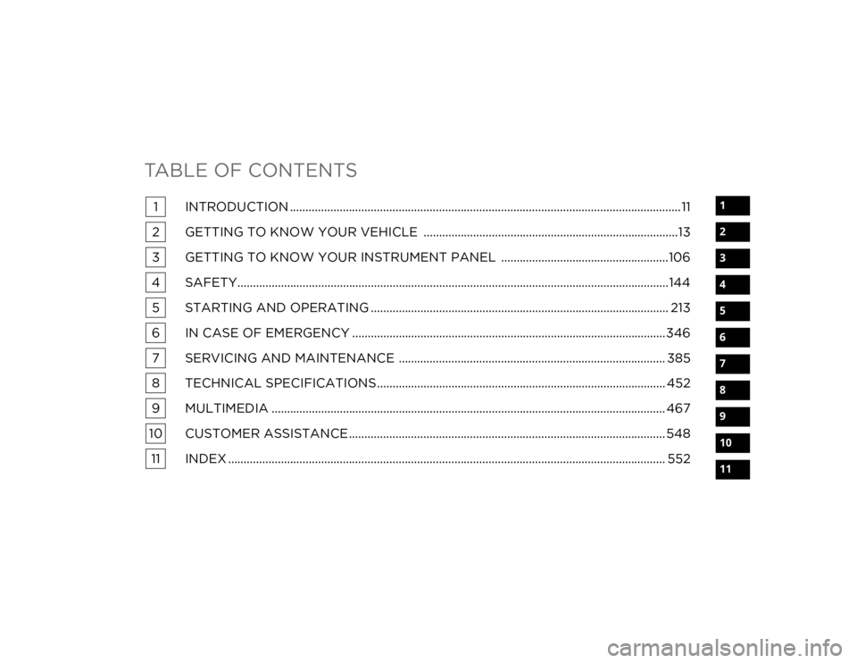
TABLE OF CONTENTS
1
2
3
4
5
6
7
8
9
10
11
1 INTRODUCTION ..............................................................................................................................11
2 GETTING TO KNOW YOUR VEHICLE ..................................................................................13
3 GETTING TO KNOW YOUR INSTRUMENT PANEL ......................................................106
4 SAFETY...........................................................................................................................................144 5 STARTING AND OPERATING ................................................................................................ 213
6 IN CASE OF EMERGENCY .....................................................................................................346 7 SERVICING AND MAINTENANCE ...................................................................................... 385
8 TECHNICAL SPECIFICATIONS ............................................................................................. 452
9 MULTIMEDIA ............................................................................................................................... 467
10 CUSTOMER ASSISTANCE ...................................................................................................... 548 11 INDEX ............................................................................................................................................. 552
20_DJD2_OM_EN_USC_t.book Page 1
Page 11 of 568
9
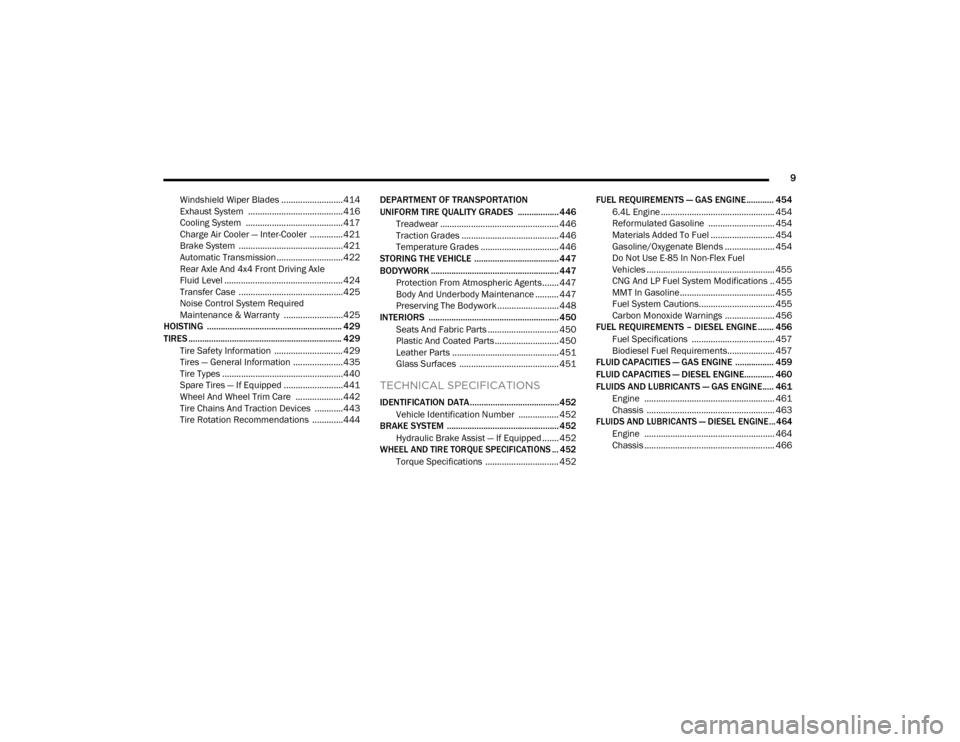
Windshield Wiper Blades ..........................414
Exhaust System ........................................416
Cooling System .........................................417
Charge Air Cooler — Inter-Cooler ..............421
Brake System ............................................421
Automatic Transmission ............................422
Rear Axle And 4x4 Front Driving Axle
Fluid Level .................................................. 424 Transfer Case ............................................425
Noise Control System Required
Maintenance & Warranty .........................425
HOISTING ........................................................... 429
TIRES ................................................................... 429
Tire Safety Information .............................429Tires — General Information .....................435Tire Types ...................................................440
Spare Tires — If Equipped .........................441
Wheel And Wheel Trim Care ....................442
Tire Chains And Traction Devices ............443
Tire Rotation Recommendations .............444 DEPARTMENT OF TRANSPORTATION
UNIFORM TIRE QUALITY GRADES .................. 446
Treadwear .................................................. 446
Traction Grades ......................................... 446
Temperature Grades ................................. 446
STORING THE VEHICLE .....................................447
BODYWORK ........................................................ 447
Protection From Atmospheric Agents....... 447
Body And Underbody Maintenance .......... 447Preserving The Bodywork .......................... 448
INTERIORS ......................................................... 450
Seats And Fabric Parts .............................. 450
Plastic And Coated Parts ........................... 450
Leather Parts ............................................. 451
Glass Surfaces .......................................... 451
TECHNICAL SPECIFICATIONS
IDENTIFICATION DATA .......................................452Vehicle Identification Number ................. 452
BRAKE SYSTEM ................................................. 452
Hydraulic Brake Assist — If Equipped ....... 452
WHEEL AND TIRE TORQUE SPECIFICATIONS ... 452
Torque Specifications ............................... 452 FUEL REQUIREMENTS — GAS ENGINE ............ 454
6.4L Engine ................................................ 454
Reformulated Gasoline ............................ 454Materials Added To Fuel ........................... 454
Gasoline/Oxygenate Blends ..................... 454
Do Not Use E-85 In Non-Flex Fuel
Vehicles ...................................................... 455 CNG And LP Fuel System Modifications .. 455MMT In Gasoline........................................ 455
Fuel System Cautions................................ 455
Carbon Monoxide Warnings ..................... 456
FUEL REQUIREMENTS – DIESEL ENGINE ....... 456
Fuel Specifications ................................... 457
Biodiesel Fuel Requirements.................... 457
FLUID CAPACITIES — GAS ENGINE ................. 459
FLUID CAPACITIES — DIESEL ENGINE............. 460
FLUIDS AND LUBRICANTS — GAS ENGINE..... 461 Engine ....................................................... 461
Chassis ...................................................... 463
FLUIDS AND LUBRICANTS — DIESEL ENGINE ...464
Engine ....................................................... 464
Chassis ....................................................... 466
20_DJD2_OM_EN_USC_t.book Page 9
Page 14 of 568
12
HOW TO USE THIS MANUAL
ESSENTIAL INFORMATION
Consult the Table of Contents to determine which section contains the
information you desire.
Since the specification of your vehicle depends on the items of equipment
ordered, certain descriptions and illustrations may differ from your
vehicle's equipment.
The detailed Index at the back of this Owner's Manual contains a
complete listing of all subjects.
SYMBOLS
Some vehicle components have colored labels whose symbols indicate
precautions to be observed when using this component. Refer to
“Warning Lights and Messages” in “Getting To Know Your Instrument
Panel” for further information on the symbols used in your vehicle.
WARNINGS AND CAUTIONS
This Owner’s Manual contains WARNINGS against operating procedures
that could result in a collision, bodily injury and/or death. It also contains
CAUTIONS against procedures that could result in damage to your vehicle.
If you do not read this entire Owner’s Manual, you may miss important
information. Observe all Warnings and Cautions.
VAN CONVERSIONS/CAMPERS
The New Vehicle Limited Warranty does not apply to body modifications or
special equipment installed by van conversion/camper manufacturers/
body builders. US residents refer to the Warranty Information, Section
2.1.C. Canadian residents refer to the “What Is Not Covered” section of
the Warranty Information. Such equipment includes video monitors,
VCRs, heaters, stoves, refrigerators, etc. For warranty coverage and
service on these items, contact the applicable manufacturer.
Operating instructions for the special equipment installed by the
conversion/camper manufacturer should also be supplied with your
vehicle. If these instructions are missing, please contact an authorized
dealer for assistance in obtaining replacement documents from the
applicable manufacturer.
For information on the Body Builder’s Guide refer to www.ramtrucks.com.
This website contains dimensional and technical specifications for your
vehicle. It is intended for Second Stage Manufacturer's technical support.
For service issues, contact an authorized dealer.
VEHICLE MODIFICATIONS/ALTERATIONS
WARNING!
Any modifications or alterations to this vehicle could seriously affect its
roadworthiness and safety and may lead to a collision resulting in
serious injury or death.
20_DJD2_OM_EN_USC_t.book Page 12
Page 137 of 568
GETTING TO KNOW YOUR INSTRUMENT PANEL135
The ESC system will make buzzing or clicking
sounds when it is active. This is normal; the
sounds will stop when ESC becomes inactive.
This light will come on when the vehicle is in
an ESC event.
Electronic Stability Control (ESC) OFF
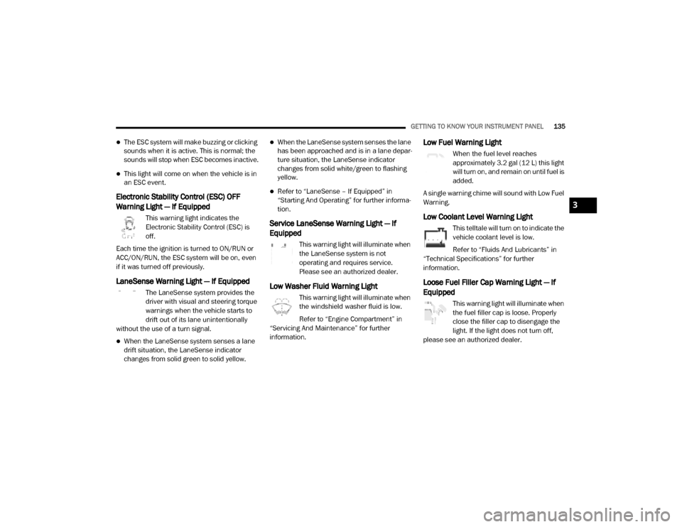
Warning Light — If Equipped
This warning light indicates the
Electronic Stability Control (ESC) is
off.
Each time the ignition is turned to ON/RUN or
ACC/ON/RUN, the ESC system will be on, even
if it was turned off previously.
LaneSense Warning Light — If Equipped
The LaneSense system provides the
driver with visual and steering torque
warnings when the vehicle starts to
drift out of its lane unintentionally
without the use of a turn signal.
When the LaneSense system senses a lane
drift situation, the LaneSense indicator
changes from solid green to solid yellow.
When the LaneSense system senses the lane
has been approached and is in a lane depar -
ture situation, the LaneSense indicator
changes from solid white/green to flashing
yellow.
Refer to “LaneSense – If Equipped” in
“Starting And Operating” for further informa -
tion.
Service LaneSense Warning Light — If
Equipped
This warning light will illuminate when
the LaneSense system is not
operating and requires service.
Please see an authorized dealer.
Low Washer Fluid Warning Light
This warning light will illuminate when
the windshield washer fluid is low.
Refer to “Engine Compartment” in
“Servicing And Maintenance” for further
information.
Low Fuel Warning Light
When the fuel level reaches
approximately 3.2 gal (12 L) this light
will turn on, and remain on until fuel is
added.
A single warning chime will sound with Low Fuel
Warning.
Low Coolant Level Warning Light
This telltale will turn on to indicate the
vehicle coolant level is low.
Refer to “Fluids And Lubricants” in
“Technical Specifications” for further
information.
Loose Fuel Filler Cap Warning Light — If
Equipped
This warning light will illuminate when
the fuel filler cap is loose. Properly
close the filler cap to disengage the
light. If the light does not turn off,
please see an authorized dealer.
3
20_DJD2_OM_EN_USC_t.book Page 135
Page 227 of 568
STARTING AND OPERATING225
The fuel grade should be clearly marked on
the pump at the fuel station.
The engine requires the use of “Ultra Low
Sulfur Diesel Fuel”. Use of incorrect fuel
could result in engine and exhaust system
damage. Refer to “Fuel Requirements” in
“Technical Specifications” for further infor -
mation.
If climatized or diesel Number 1 ULSD fuel is
not available, and you are operating below
(20°F/-6°C), in sustained arctic conditions,
Mopar Premium Diesel Fuel Treatment (or
equivalent) is recommended to avoid gelling
(see Fuel Operating Range Chart).
Under some circumstances increased engine
noise may be audible in the seconds
following a cold start. This is most likely to
occur when using fuel that isn't blended for
the ambient temperature present. This may
occur on an unseasonably cold day or when a
truck is fueled in a warmer climate and driven
to a colder climate. The noise can typically be
prevented by using Mopar Premium Diesel
Fuel Treatment as recommended (see Fuel
Operating Range Chart).
Engine Oil Usage
Refer to “Dealer Service” in “Servicing And
Maintenance” for the correct engine oil
viscosity.
Winter Front Cover Usage
A Winter front or cold weather cover is to be
used in ambient temperatures below 32°F
(0°C), especially during extended idle
conditions. This cover is equipped with four
flaps for managing total grille opening in varying
ambient temperatures. If a Winter front or cold
weather cover is to be used the flaps should be
left in the full open position to allow air flow to
the charge air cooler and automatic
transmission oil cooler. When ambient
temperatures drop below 0°F (-17°C) the four
flaps need to be closed. A suitable cold weather
cover is available from your Mopar dealer.
Battery Blanket Usage
A battery loses 60% of its cranking power as the
battery temperature decreases to 0°F (-18°C).
For the same decrease in temperature, the
engine requires twice as much power to crank
at the same RPM. The use of 120 VAC powered
battery blankets will greatly increase starting capability at low temperatures. Suitable battery
blankets are available from an authorized
Mopar dealer.
Engine Warm-Up
Avoid full throttle operation when the engine is
cold. When starting a cold engine, bring the
engine up to operating speed slowly to allow the
oil pressure to stabilize as the engine warms up.
NOTE:
High-speed, no-load running of a cold engine
can result in excessive white smoke and poor
engine performance. No-load engine speeds
should be kept under 1,000 RPM during the
warm-up period, especially in cold ambient
temperature conditions.
Your vehicle is equipped with an engine warm
up protection feature that may limit engine
performance after cold starting at low ambient
temperatures. The length of time engine speed
is limited is dependent upon engine coolant
temperature. Engine speed may be briefly
limited to 1000 RPM after starting with coolant
temperature below freezing conditions, and
may be limited to 1000 RPM for up to
approximately 2 minutes under more severe
cold conditions.
5
20_DJD2_OM_EN_USC_t.book Page 225
Page 232 of 568
230STARTING AND OPERATING
NOTE:
The block heater will require 110 Volts AC and
6.5 Amps to activate the heater element.
BLOCK HEATER USAGE
For ambient temperatures below 0°F (-18°C),
engine block heater usage is recommended.
For ambient temperatures below –20°F
(-29°C), engine block heater usage is required.
ENGINE BREAK-IN RECOMMENDATIONS —
GAS ENGINE
A long break-in period is not required for the
engine and drivetrain (transmission and axle) in
your vehicle.
Drive moderately during the first 300 miles
(500 km). After the initial 60 miles (100 km),
speeds up to 50 or 55 mph (80 or 90 km/h) are
desirable.
While cruising, brief full-throttle acceleration
within the limits of local traffic laws contributes
to a good break-in. Wide-open throttle
acceleration in low gear can be detrimental and
should be avoided. The engine oil installed in the engine at the
factory is a high-quality energy conserving type
lubricant. Oil changes should be consistent with
anticipated climate conditions under which
vehicle operations will occur. For the
recommended viscosity and quality grades,
refer to “Fluids And Lubricants” in “Technical
Specifications”.
NOTE:
A new engine may consume some oil during its
first few thousand miles (kilometers) of opera
-
tion. This should be considered a normal part of
the break-in and not interpreted as a problem.
Please check your oil level with the engine oil
indicator often during the break in period. Add
oil as required.
ENGINE BREAK-IN RECOMMENDATIONS —
DIESEL ENGINE
The Cummins® Turbo Diesel engine does not
require a break-in period due to its construction.
Normal operation is allowed, providing the
following recommendations are followed:
Warm up the engine before placing it under
load.
Do not operate the engine at idle for
prolonged periods.
Use the appropriate transmission gear to
prevent engine lugging.
Observe vehicle oil pressure and tempera -
ture indicators.
Check the coolant and oil levels frequently.
Vary throttle position at highway speeds
when carrying or towing significant weight.
CAUTION!
Never use Non-Detergent Oil or Straight
Mineral Oil in the engine or damage may
result.
20_DJD2_OM_EN_USC_t.book Page 230
Page 324 of 568

322STARTING AND OPERATING
Temperature sensors
SCR catalyst
UQS Sensor
Refer to “Instrument Cluster Display” in
“Getting To Know Your Instrument Panel” for
system messages and warnings.
NOTE:
Your vehicle is equipped with a DEF injection
system. You may occasionally hear an audible
clicking noise. This is normal operation.
The DEF pump will run for a period of time
after engine shutdown to purge the DEF
system. This is normal operation.
Diesel Exhaust Fluid Storage
Diesel Exhaust Fluid (DEF) is considered a very
stable product with a long shelf life. If DEF is
kept in temperatures between 10°F and 90°F
(-12°C and 32°C), it will last a minimum of one
year.
DEF is subject to freezing at the lowest
temperatures. For example, DEF may freeze at
temperatures at or below 12°F (-11°C). The
system has been designed to operate in this
environment. NOTE:
When working with DEF, it is important to know
that:
Any containers or parts that come into
contact with DEF must be DEF compatible
(plastic or stainless steel). Copper, brass,
aluminum, iron or non-stainless steel should
be avoided as they are subject to corrosion
by DEF.
If DEF is spilled, it should be wiped up
completely.
Adding Diesel Exhaust Fluid
The DEF gauge (located on the instrument
cluster) will display the level of DEF remaining in
the tank. Refer to “Instrument Cluster” and
“Instrument Cluster Descriptions” in “Getting To
Know Your Instrument Panel” for further
information.
NOTE:
Driving conditions (altitude, vehicle speed,
load, etc.) will affect the amount of DEF that
is used in your vehicle.
Another factor is that outside temperature
can affect DEF consumption. In cold condi
-
tions, 12°F (-11°C) and below, the DEF gauge needle can stay on a fixed position and
may not move for extended periods of time.
This is a normal function of the system.
There is an electric heater inside the DEF
tank that automatically works when neces
-
sary. And if the DEF supply does freeze, the
truck will operate normally until it thaws.
DEF Fill Procedure
NOTE:
Refer to “Fluids And Lubricants” in “Technical
Specifications” for the correct fluid type.
1. Remove cap from DEF tank (located on driver’s side of the vehicle or in fuel door).
Fill Locations
1 — Diesel Exhaust Fluid (DEF) Fill Location
2 — Diesel Fuel Fill Location
20_DJD2_OM_EN_USC_t.book Page 322
Page 374 of 568

372IN CASE OF EMERGENCY
6. Finish tightening the lug nuts. Push down on
the lug wrench while at the end of the
handle for increased leverage. Tighten the
lug nuts in a star pattern until each nut has
been tightened twice. For the correct lug nut
torque refer to “Wheel And Tire Torque
Specifications” in “Technical Specifi -
cations”. If in doubt about the correct
tightness, have them checked with a torque
wrench by an authorized dealer or service
station.
7. Install the wheel center cap and remove the wheel blocks. Do not install chrome or
aluminum wheel center caps on the spare
wheel. This may result in cap damage. 8. Lower the jack to its fully closed position.
Stow the replaced tire, jack, and tools as
previously described.
NOTE:
The bottle jack will not lower by turning the dial
(thumbwheel) by hand, it may be necessary to
use the jack driver in order to lower the jack.
9. Adjust the tire pressure when possible.
NOTE:
Do not oil wheel studs. For chrome wheels, do
not substitute with chrome plated lug nuts.
TO STOW THE FLAT OR SPARE
NOTE:
Have the flat tire repaired or replaced immedi -
ately.
1. Turn the wheel so that the valve stem is facing the ground and toward the rear of
the vehicle for convenience in checking the
spare tire inflation. Slide the wheel retainer
through the center of the wheel.
Reinstalling The Retainer
2. Lift the spare tire with one hand to give clearance to tilt the retainer at the end of
the cable and position it properly across the
wheel opening.
WARNING!
A loose tire or jack thrown forward in a
collision or hard stop, could endanger the
occupants of the vehicle. Always stow the jack
parts and the spare tire in the places
provided.
WARNING!
A loose tire or jack thrown forward in a
collision or hard stop could endanger the
occupants of the vehicle. Always stow the jack
parts and the spare tire in the places
provided. Have the deflated (flat) tire repaired
or replaced immediately.
20_DJD2_OM_EN_USC_t.book Page 372
Page 420 of 568

418SERVICING AND MAINTENANCE
Engine Coolant Checks
Check the engine coolant (antifreeze)
protection every 12 months (before the onset of
freezing weather, where applicable). If the
engine coolant (antifreeze) is dirty or rusty in
appearance, the system should be drained,
flushed and refilled with fresh coolant. Check
the front of the A/C condenser (if equipped) or
radiator for any accumulation of bugs, leaves,
etc. If dirty, clean by gently spraying water from
a garden hose vertically down the face of the
A/C condenser (if equipped) or the back of the
radiator core.
Check the engine cooling system hoses for
brittle rubber, cracking, tears, cuts and
tightness of the connection at the coolant
recovery bottle and radiator. Inspect the entire
system for leaks.
DO NOT REMOVE THE COOLANT PRESSURE CAP
WHEN THE COOLING SYSTEM IS HOT.
Cooling System — Drain, Flush And Refill
NOTE:
Some vehicles require special tools to add
coolant properly. Failure to fill these systems
properly could lead to severe internal engine damage. If any coolant is needed to be added to
the system please contact an authorized
dealer.
If the engine coolant (antifreeze) is dirty or
contains visible sediment, have an authorized
dealer clean and flush with OAT coolant
(antifreeze) (conforming to MS.90032).
Refer to the “Maintenance Plan” in this section
for the proper maintenance intervals.
Selection Of Coolant
Refer to “Fluids And Lubricants” in “Technical
Specifications” for further information.
NOTE:
Mixing of engine coolant (antifreeze) other
than specified Organic Additive Technology
(OAT) engine coolant (antifreeze), may result
in engine damage and may decrease corro
-
sion protection. Organic Additive Technology
(OAT) engine coolant is different and should
not be mixed with Hybrid Organic Additive
Technology (HOAT) engine coolant (anti -
freeze) or any “globally compatible” coolant
(antifreeze). If a non-OAT engine coolant
(antifreeze) is introduced into the cooling
system in an emergency, the cooling system will need to be drained, flushed, and refilled
with fresh OAT coolant (conforming to
MS.90032), by an authorized dealer as soon
as possible.
Do not use water alone or alcohol-based
engine coolant (antifreeze) products. Do not
use additional rust inhibitors or antirust prod
-
ucts, as they may not be compatible with the
radiator engine coolant and may plug the
radiator.
This vehicle has not been designed for use
with propylene glycol-based engine coolant
(antifreeze). Use of propylene glycol-based
engine coolant (antifreeze) is not recom -
mended.
Some vehicles require special tools to add
coolant properly. Failure to fill these systems
properly could lead to severe internal engine
damage. If any coolant is needed to be added
to the system please contact an authorized
dealer.
Adding Coolant
Your vehicle has been built with an improved
engine coolant (OAT coolant conforming to
MS.90032) that allows extended maintenance
intervals. This engine coolant (antifreeze) can
20_DJD2_OM_EN_USC_t.book Page 418
Page 423 of 568
SERVICING AND MAINTENANCE421
(Continued)
CHARGE AIR COOLER — INTER-COOLER
The charge air cooler is positioned below the
radiator and the air conditioner condenser. Air
enters the engine through the air cleaner and
passes through the turbocharger, where it is
pressurized. This pressurized air rapidly
reaches high temperature. The air is then
directed through a hose to the charge air cooler
and through another hose to the intake
manifold of the engine. The air entering the
engine has been cooled by about 50° to 100°F
(10° to 38°C). This cooling process enables
more efficient burning of fuel resulting in fewer
emissions.
To guarantee optimum performance of the
system, keep the surfaces of the charge air
cooler, condenser and radiator clean and free
of debris. Periodically check the hoses leading
to and from the charge air cooler for cracks or
loose clamps resulting in loss of pressure and
reduced engine performance.
BRAKE SYSTEM
In order to ensure brake system performance,
all brake system components should be
inspected periodically. Refer to the “Maintenance Plan” in this section for the
proper maintenance intervals.
Fluid Level Check — Brake Master Cylinder
The fluid level of the master cylinder should be
checked when performing under the hood
service or immediately if the brake system
warning lamp indicates system failure.
If necessary, add fluid to bring level within the
designated marks on the side of the reservoir of
the brake master cylinder. Be sure to clean the
top of the master cylinder area before removing
cap.
With disc brakes the fluid level can be expected
to fall as the brake linings wear. However, an
unexpected drop in fluid level may be caused by
a leak and a system check should be
conducted.
Refer to “Fluids And Lubricants” in “Technical
Specifications” for further information.
WARNING!
Riding the brakes can lead to brake failure
and possibly a collision. Driving with your foot
resting or riding on the brake pedal can result
in abnormally high brake temperatures,
excessive lining wear, and possible brake
damage. You would not have your full braking
capacity in an emergency.
WARNING!
Use only manufacturer's recommended
brake fluid. Refer to “Fluids And Lubricants”
in “Technical Specifications” for further infor-
mation. Using the wrong type of brake fluid
can severely damage your brake system
and/or impair its performance. The proper
type of brake fluid for your vehicle is also
identified on the original factory installed
hydraulic master cylinder reservoir.
To avoid contamination from foreign matter
or moisture, use only new brake fluid or fluid
that has been in a tightly closed container.
Keep the master cylinder reservoir cap
secured at all times. Brake fluid in a open
container absorbs moisture from the air
resulting in a lower boiling point. This may
cause it to boil unexpectedly during hard or
prolonged braking, resulting in sudden brake
failure. This could result in a collision.
7
20_DJD2_OM_EN_USC_t.book Page 421