engine Ram 3500 Chassis Cab 2019 Owner's Guide
[x] Cancel search | Manufacturer: RAM, Model Year: 2019, Model line: 3500 Chassis Cab, Model: Ram 3500 Chassis Cab 2019Pages: 607, PDF Size: 10.72 MB
Page 70 of 607

68 GETTING TO KNOW YOUR VEHICLE
If the windshield or Automatic High Beam Headlamp
Control mirror is replaced, the mirror must be re-aimed to
ensure proper performance. See a local authorized dealer.
To Activate
1. The Automatic High Beams are enabled through theUconnect system. Refer to “Uconnect Settings” in “Multi -
media” for further information.
2. Turn the headlight switch to the AUTO headlight posi -
tion.
3. Push the multifunction lever away from you (toward front of vehicle) to engage the high beam mode.
NOTE:
The Automatic High Beams will not activate until the vehicle
is at or above 12 mph (20 km/h).
To Deactivate
1. Pull the multifunction lever toward you (or rearward in vehicle) to manually deactivate the system (normal oper -
ation of low beams).
2. Push back on the multifunction lever to reactivate the system. The Automatic High Beams can also be deactivated through
the Uconnect system. Refer to “Uconnect Settings” in “Multi
-
media” for further information.
Flash-To-Pass
You can signal another vehicle with your headlights by
lightly pulling the multifunction lever toward you. This will
cause the high beam headlights to turn on, and remain on,
until the lever is released.
Automatic Headlights — If Equipped
This system automatically turns your headlights on or off
based on ambient light levels. To turn the system on, turn the
headlight switch to the extreme clockwise position aligning
the indicator with the AUTO on the headlight switch. When
the system is on, the Headlight Time Delay feature is also on.
This means your headlights will stay on for up to 90 seconds
after you turn the ignition switch OFF. To turn the Auto -
matic System off, turn the headlight switch counterclockwise
to the O (off) position.
NOTE:
The engine must be running before the headlights will come
on in the Automatic mode.
Page 91 of 607

GETTING TO KNOW YOUR VEHICLE 89
Automatic Temperature Control (ATC)
Automatic Operation
1. Push the AUTO button on the faceplate, or the AUTObutton on the touchscreen on the Automatic Temperature
Control (ATC) Panel.
2. Next, adjust the temperature you would like the system to maintain by adjusting the driver and passenger
temperature control buttons. Once the desired tempera -
ture is displayed, the system will achieve and automati -
cally maintain that comfort level.
3. When the system is set up for your comfort level, it is not necessary to change the settings. You will experience the
greatest efficiency by simply allowing the system to func -
tion automatically.
NOTE:
• It is not necessary to move the temperature settings for cold or hot vehicles. The system automatically adjusts the
temperature, mode, and blower speed to provide comfort
as quickly as possible. • The temperature can be displayed in U.S. or Metric units
by selecting the US/Metric customer-programmable
feature. Refer to the “Uconnect Settings” in “Multimedia”
for further information.
To provide you with maximum comfort in the Automatic
mode during cold start-ups, the blower fan will remain on
low until the engine warms up. The blower will increase in
speed and transition into Auto mode.
Manual Operation Override
This system offers a full complement of manual override
features. The AUTO symbol in the front ATC display will be
turned off when the system is being used in the manual
mode.
Operating Tips
NOTE:
Refer to the chart at the end of this section for suggested
control settings for various weather conditions.
2
Page 92 of 607

90 GETTING TO KNOW YOUR VEHICLE
Summer Operation
The engine cooling system must be protected with a
high-quality antifreeze coolant to provide proper corrosion
protection and to protect against engine overheating. OAT
coolant (conforming to MS.90032) is recommended.
Winter Operation
To ensure the best possible heater and defroster perfor-
mance, make sure the engine cooling system is functioning
properly and the proper amount, type, and concentration of
coolant is used. Use of the Air Recirculation mode during
Winter months is not recommended, because it may cause
window fogging.
Vacation/Storage
Before you store your vehicle, or keep it out of service (i.e.,
vacation) for two weeks or more, run the air conditioning
system at idle for about five minutes, in fresh air with the
blower setting on high. This will ensure adequate system
lubrication to minimize the possibility of compressor
damage when the system is started again. Window Fogging
Vehicle windows tend to fog on the inside in mild, rainy,
and/or humid weather. To clear the windows, select Defrost
or Mix mode and increase the front blower speed. Do not use
the Recirculation mode without A/C for long periods, as
fogging may occur.
CAUTION!
Failure to follow these cautions can cause damage to the
heating elements:
• Use care when washing the inside of the rear window. Do not use abrasive window cleaners on the interior
surface of the window. Use a soft cloth and a mild
washing solution, wiping parallel to the heating
elements. Labels can be peeled off after soaking with
warm water.
• Do not use scrapers, sharp instruments, or abrasive window cleaners on the interior surface of the window.
• Keep all objects a safe distance from the window.
Page 98 of 607

96 GETTING TO KNOW YOUR VEHICLE
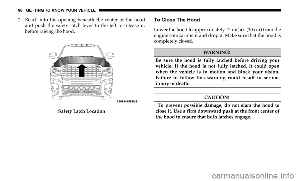
2. Reach into the opening beneath the center of the hoodand push the safety latch lever to the left to release it,
before raising the hood.
Safety Latch LocationTo Close The Hood
Lower the hood to approximately 12 inches (30 cm) from the
engine compartment and drop it. Make sure that the hood is
completely closed.
WARNING!
Be sure the hood is fully latched before driving your
vehicle. If the hood is not fully latched, it could open
when the vehicle is in motion and block your vision.
Failure to follow this warning could result in serious
injury or death.
CAUTION!
To prevent possible damage, do not slam the hood to
close it. Use a firm downward push at the front center of
the hood to ensure that both latches engage.
Page 121 of 607

GETTING TO KNOW YOUR VEHICLE 119
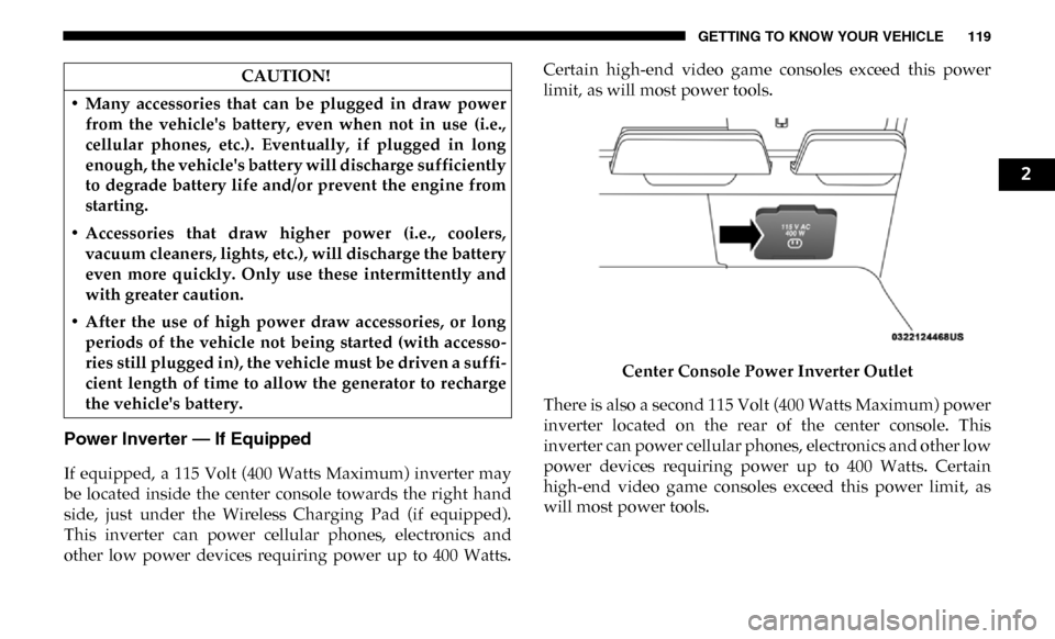
Power Inverter — If Equipped
If equipped, a 115 Volt (400 Watts Maximum) inverter may
be located inside the center console towards the right hand
side, just under the Wireless Charging Pad (if equipped).
This inverter can power cellular phones, electronics and
other low power devices requiring power up to 400 Watts.Certain high-end video game consoles exceed this power
limit, as will most power tools.
Center Console Power Inverter Outlet
There is also a second 115 Volt (400 Watts Maximum) power
inverter located on the rear of the center console. This
inverter can power cellular phones, electronics and other low
power devices requiring power up to 400 Watts. Certain
high-end video game consoles exceed this power limit, as
will most power tools.
CAUTION!
• Many accessories that can be plugged in draw power from the vehicle's battery, even when not in use (i.e.,
cellular phones, etc.). Eventually, if plugged in long
enough, the vehicle's battery will discharge sufficiently
to degrade battery life and/or prevent the engine from
starting.
• Accessories that draw higher power (i.e., coolers, vacuum cleaners, lights, etc.), will discharge the battery
even more quickly. Only use these intermittently and
with greater caution.
• After the use of high power draw accessories, or long periods of the vehicle not being started (with accesso -
ries still plugged in), the vehicle must be driven a suffi -
cient length of time to allow the generator to recharge
the vehicle's battery.
2
Page 126 of 607

124 GETTING TO KNOW YOUR INSTRUMENT PANEL
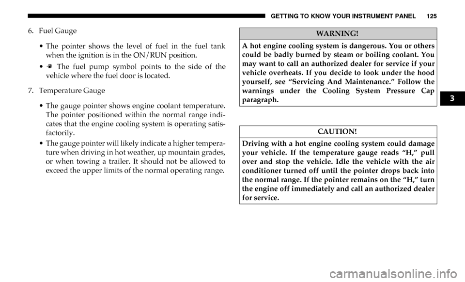
Base / Midline Instrument Cluster Descriptions
1. Tachometer• Indicates the engine speed in revolutions per minute(RPM x 1000).
2. Voltmeter
• When the vehicle is in the RUN state, the gauge indi -
cates the electrical system voltage. The pointer should
stay within the normal range if the battery is charged.
If the pointer moves to either extreme left or right and
remains there during normal driving, the electrical
system should be serviced.
3. Instrument Cluster Display
• When the appropriate conditions exist, this displayshows the instrument cluster display messages. Refer
to “Instrument Cluster Display” in “Getting To Know
Your Instrument Panel” for further information. 4. Oil Pressure Gauge
• The pointer should always indicate the oil pressurewhen the engine is running. A continuous high or low
reading under normal driving conditions may indicate
a lubrication system malfunction. Immediate service
should be obtained from an authorized dealer.
NOTE:
In vehicles equipped with Stop/Start, an oil pressure indica -
tion of zero is normal during an Autostop.
5. Speedometer
• Indicates vehicle speed.
Page 127 of 607

GETTING TO KNOW YOUR INSTRUMENT PANEL 125
6. Fuel Gauge• The pointer shows the level of fuel in the fuel tankwhen the ignition is in the ON/RUN position.
• The fuel pump symbol points to the side of the vehicle where the fuel door is located.
7. Temperature Gauge
• The gauge pointer shows engine coolant temperature.The pointer positioned within the normal range indi -
cates that the engine cooling system is operating satis -
factorily.
• The gauge pointer will likely indicate a higher tempera -
ture when driving in hot weather, up mountain grades,
or when towing a trailer. It should not be allowed to
exceed the upper limits of the normal operating range.WARNING!
A hot engine cooling system is dangerous. You or others
could be badly burned by steam or boiling coolant. You
may want to call an authorized dealer for service if your
vehicle overheats. If you decide to look under the hood
yourself, see “Servicing And Maintenance.” Follow the
warnings under the Cooling System Pressure Cap
paragraph.
CAUTION!
Driving with a hot engine cooling system could damage
your vehicle. If the temperature gauge reads “H,” pull
over and stop the vehicle. Idle the vehicle with the air
conditioner turned off until the pointer drops back into
the normal range. If the pointer remains on the “H,” turn
the engine off immediately and call an authorized dealer
for service.
3
Page 129 of 607

GETTING TO KNOW YOUR INSTRUMENT PANEL 127
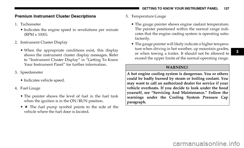
Premium Instrument Cluster Descriptions
1. Tachometer• Indicates the engine speed in revolutions per minute(RPM x 1000).
2. Instrument Cluster Display
• When the appropriate conditions exist, this displayshows the instrument cluster display messages. Refer
to “Instrument Cluster Display” in “Getting To Know
Your Instrument Panel” for further information.
3. Speedometer
• Indicates vehicle speed.
4. Fuel Gauge
• The pointer shows the level of fuel in the fuel tankwhen the ignition is in the ON/RUN position.
• The fuel pump symbol points to the side of the vehicle where the fuel door is located. 5. Temperature Gauge
• The gauge pointer shows engine coolant temperature.The pointer positioned within the normal range indi -
cates that the engine cooling system is operating satis -
factorily.
• The gauge pointer will likely indicate a higher tempera -
ture when driving in hot weather, up mountain grades,
or when towing a trailer. It should not be allowed to
exceed the upper limits of the normal operating range.
WARNING!
A hot engine cooling system is dangerous. You or others
could be badly burned by steam or boiling coolant. You
may want to call an authorized dealer for service if your
vehicle overheats. If you decide to look under the hood
yourself, see “Servicing And Maintenance.” Follow the
warnings under the Cooling System Pressure Cap
paragraph.
3
Page 130 of 607

128 GETTING TO KNOW YOUR INSTRUMENT PANEL
INSTRUMENT CLUSTER DISPLAY
Your vehicle will be equipped with an instrument cluster
display, which offers useful information to the driver. With
the ignition in the STOP/OFF mode, opening/closing of a
door will activate the display for viewing, and display the
total miles, or kilometers, in the odometer. Your instrument
cluster display is designed to display important information
about your vehicle’s systems and features. Using a driver
interactive display located on the instrument panel, your
instrument cluster display can show you how systems are
working and give you warnings when they are not. The
steering wheel mounted controls allow you to scroll through
the main menus and submenus. You can access the specific
information you want and make selections and adjustments.
Instrument Cluster Display Controls
The instrument cluster display features a driver-interactive
display that is located in the instrument cluster.Base Instrument Cluster Display
CAUTION!
Driving with a hot engine cooling system could damage
your vehicle. If the temperature gauge reads “H,” pull
over and stop the vehicle. Idle the vehicle with the air
conditioner turned off until the pointer drops back into
the normal range. If the pointer remains on the “H,” turn
the engine off immediately and call an authorized dealer
for service.
1 – Instrument Cluster Display Controls
2 – Instrument Cluster Display Screen
Page 132 of 607

130 GETTING TO KNOW YOUR INSTRUMENT PANEL
•Up Arrow Button
Push and release the up arrow button to scroll
upward through the main menu items, submenu
screen, and vehicle settings.
•Down Arrow Button
Push and release the down arrow button to scroll
downward through the main menu items,
submenu screen, and vehicle settings.
•Right Arrow Button
Push and release the right arrow button to access/
select the information screens or submenu screens
of a main menu item. Push and hold the RIGHT arrow
button for two seconds to reset displayed/selected
features that can be reset.
•Left Arrow Button
Push and release the left arrow button to access/
select the information screens, submenu screens of
a main menu item, or to return to the main menu.Oil Life Reset
Your vehicle is equipped with an engine oil change indicator
system. The “Oil Change Required” message will display in
the instrument cluster display after a single chime has
sounded, to indicate the next scheduled oil change interval.
The engine oil change indicator system is duty cycle based,
which means the engine oil change interval may fluctuate,
dependent upon your personal driving style.
NOTE:
Use the steering wheel instrument cluster display controls
for the following procedure.