stop start Ram 3500 Chassis Cab 2019 Owner's Manual
[x] Cancel search | Manufacturer: RAM, Model Year: 2019, Model line: 3500 Chassis Cab, Model: Ram 3500 Chassis Cab 2019Pages: 607, PDF Size: 10.72 MB
Page 7 of 607

5
WARNING LIGHTS AND MESSAGES ........................ 146
Red Warning Lights .................................................... 146
Yellow Warning Lights............................................... 150
Yellow Indicator Lights .............................................. 155
Green Indicator Lights ................................................ 156
White Indicator Lights ................................................ 157
Blue Indicator Lights ................................................... 158
ONBOARD DIAGNOSTIC SYSTEM — OBD II ........ 158
Onboard Diagnostic System (OBD II)
Cybersecurity ............................................................... 159
EMISSIONS INSPECTION AND MAINTENANCE
PROGRAMS ..................................................................... 159
SAFETY
SAFETY FEATURES ......................................................... 161
Anti-Lock Brake System (ABS) ................................. 161
Electronic Brake Control System .............................. 162
AUXILIARY DRIVING SYSTEMS .................................. 174
Forward Collision Warning (FCW) With Mitigation —
If Equipped ................................................................... 174
Tire Pressure Monitoring System (TPMS) ............ 177
OCCUPANT RESTRAINT SYSTEMS ...........................187
Occupant Restraint Systems Features ......................187
Important Safety Precautions.....................................188
Seat Belt Systems .........................................................189
Supplemental Restraint Systems (SRS).....................202
Child Restraints ..........................................................214
Transporting Pets ......................................................240
SAFETY TIPS ...................................................................240
Transporting Passengers ............................................240
Exhaust Gas ..............................................................240
Safety Checks You Should Make Inside The
Vehicle ..........................................................................241
Periodic Safety Checks You Should Make Outside The
Vehicle ...........................................................................243
STARTING AND OPERATING
STARTING THE ENGINE ..............................................244
Automatic Transmission.............................................245
Tip Start Feature ..........................................................245
Keyless Enter-N-Go — Ignition ................................. 245
Normal Starting Using ENGINE START/STOP
Button .........................................................................246
Cold Weather Operation (Below –22°F Or −30°C) ... 250
After Starting ................................................................250
ENGINE BLOCK HEATER — IF EQUIPPED............... 251
Page 19 of 607

GETTING TO KNOW YOUR VEHICLE 17
KEYS
Key Fob
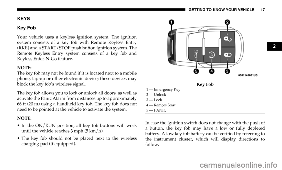
Your vehicle uses a keyless ignition system. The ignition
system consists of a key fob with Remote Keyless Entry
(RKE) and a START/STOP push button ignition system. The
Remote Keyless Entry system consists of a key fob and
Keyless Enter-N-Go feature.
NOTE:
The key fob may not be found if it is located next to a mobile
phone, laptop or other electronic device; these devices may
block the key fob’s wireless signal.
The key fob allows you to lock or unlock all doors, as well as
activate the Panic Alarm from distances up to approximately
66 ft (20 m) using a handheld key fob. The key fob does not
need to be pointed at the vehicle to activate the system.
NOTE:
• In the ON/RUN position, all key fob buttons will workuntil the vehicle reaches 3 mph (5 km/h).
• The key fob should not be placed next to the wireless charging pad (if equipped). Key Fob
In case the ignition switch does not change with the push of
a button, the key fob may have a low or fully depleted
battery. A low key fob battery can be verified by referring to
the instrument cluster, which will display directions to
follow.
1 — Emergency Key
2 — Unlock
3 — Lock
4 — Remote Start
5 — PANIC
2
Page 20 of 607

18 GETTING TO KNOW YOUR VEHICLE
In a situation where the battery is low or fully depleted, a
back up method can be used to operate the ignition switch.
Put the nose side of the key fob (side opposite of the Emer-
gency Key) against the ENGINE START/STOP button and
push to operate the ignition switch.
To Unlock The Doors
Push and release the unlock button on the key fob once to
unlock the driver’s door. Push the unlock button twice
within five seconds to unlock all doors. The turn signal lights
will flash to acknowledge the unlock signal. The illuminated
entry system will also turn on.
NOTE:
The instrument cluster display or Uconnect Settings are
setup for driver door first, otherwise this will unlock all
doors.
To Lock The Doors
Push and release the lock button on the key fob to lock all
doors. The turn signal lights will flash and the horn will
chirp to acknowledge the signal. Sound Horn With Remote Key Lock
This feature will cause the horn to chirp when the doors are
locked with the key fob. This feature can be turned on or
turned off.
NOTE:
Pushing the lock button on the key fob while you are in the
vehicle will activate the vehicle security alarm system.
Opening a door with the vehicle security alarm system acti
-
vated will cause the alarm to sound. Push the unlock button
to deactivate the vehicle security alarm system.
Refer to “Instrument Cluster Display” in “Getting To Know
Your Instrument Panel” for further information.
Using The Panic Alarm
To turn the Panic Alarm feature on or off, push the Panic
button on the key fob. When the Panic Alarm is activated, the
turn signals will flash, the horn will pulse on and off, and the
interior lights will turn on.
Page 25 of 607

GETTING TO KNOW YOUR VEHICLE 23
Programming Additional Key Fobs
Programming the key fob may be performed by an autho-
rized dealer.
NOTE:
Once a key fob is programmed to a vehicle, it cannot be
repurposed and reprogrammed to another vehicle.
General Information
The following regulatory statement applies to all radio
frequency (RF) devices equipped in this vehicle:
This device complies with Part 15 of the FCC Rules and with
Industry Canada license-exempt RSS standard(s). Operation
is subject to the following two conditions:
1. This device may not cause harmful interference, and
2. This device must accept any interference received, including interference that may cause undesired opera -
tion.
NOTE:
Changes or modifications not expressly approved by the
party responsible for compliance could void the user’s
authority to operate the equipment.IGNITION SWITCH
Keyless Push Button Ignition
This feature allows the driver to operate the ignition switch
with the push of a button as long as the Remote Keyless
Entry key fob is in the passenger compartment.
The Keyless Push Button Ignition has four operating posi -
tions; three of which are labeled and will illuminate when in
position. The three positions are OFF, ACC, and ON/RUN.
The fourth position is START, during start RUN will illumi -
nate.
NOTE:
In case the ignition switch does not change with the push of
a button, the key fob may have a low or dead battery. In this
situation, a back up method can be used to operate the igni -
tion switch. Put the nose side (side opposite of the emer -
gency key) of the key fob against the ENGINE START/STOP
button, with your foot applied on the brake pedal, and push
to operate the ignition switch.
2
Page 26 of 607

24 GETTING TO KNOW YOUR VEHICLE
(Continued)
Keyless Push Button Ignition
The push button ignition can be placed in the following
modes:
OFF
• The engine is stopped.
• Some electrical devices (e.g. Central locking, alarm, etc.) are still available. ACC
• Engine is not started.
• Some electrical devices are available.
RUN
• Driving position.
• All the electrical devices are available.
START
• The engine will start.
1 — OFF
2 — ACC (Accessory)
3 — ON/RUN
WARNING!
• When exiting the vehicle, always remove the key fob from the vehicle and lock your vehicle.
• Never leave children alone in a vehicle, or with access to an unlocked vehicle.
• Allowing children to be in a vehicle unattended is dangerous for a number of reasons. A child or others
could be seriously or fatally injured. Children should
be warned not to touch the parking brake, brake pedal
or the gear selector.
Page 27 of 607

GETTING TO KNOW YOUR VEHICLE 25
The engine only runs in the ON/RUN ignition position or
from a remote start request.
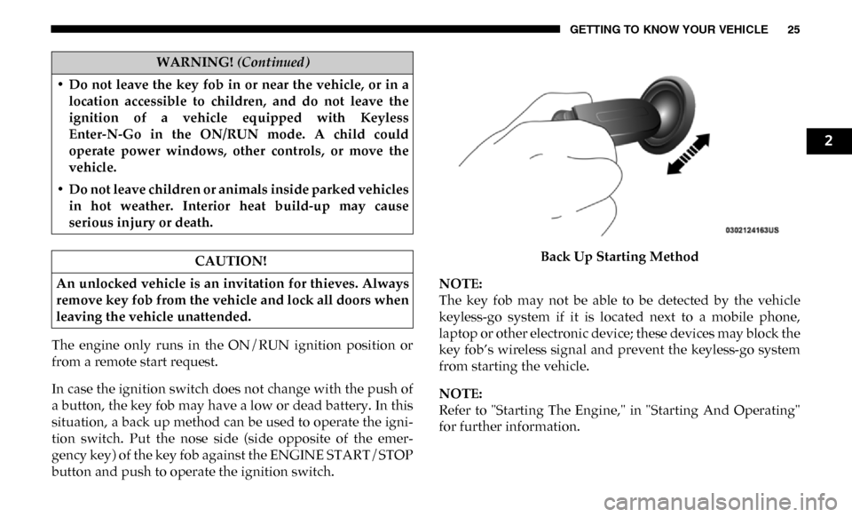
In case the ignition switch does not change with the push of
a button, the key fob may have a low or dead battery. In this
situation, a back up method can be used to operate the igni-
tion switch. Put the nose side (side opposite of the emer -
gency key) of the key fob against the ENGINE START/STOP
button and push to operate the ignition switch. Back Up Starting Method
NOTE:
The key fob may not be able to be detected by the vehicle
keyless-go system if it is located next to a mobile phone,
laptop or other electronic device; these devices may block the
key fob’s wireless signal and prevent the keyless-go system
from starting the vehicle.
NOTE:
Refer to "Starting The Engine," in "Starting And Operating"
for further information.
• Do not leave the key fob in or near the vehicle, or in a
location accessible to children, and do not leave the
ignition of a vehicle equipped with Keyless
Enter-N-Go in the ON/RUN mode. A child could
operate power windows, other controls, or move the
vehicle.
• Do not leave children or animals inside parked vehicles in hot weather. Interior heat build-up may cause
serious injury or death.
CAUTION!
An unlocked vehicle is an invitation for thieves. Always
remove key fob from the vehicle and lock all doors when
leaving the vehicle unattended.
WARNING! (Continued)
2
Page 126 of 607

124 GETTING TO KNOW YOUR INSTRUMENT PANEL
Base / Midline Instrument Cluster Descriptions
1. Tachometer• Indicates the engine speed in revolutions per minute(RPM x 1000).
2. Voltmeter
• When the vehicle is in the RUN state, the gauge indi -
cates the electrical system voltage. The pointer should
stay within the normal range if the battery is charged.
If the pointer moves to either extreme left or right and
remains there during normal driving, the electrical
system should be serviced.
3. Instrument Cluster Display
• When the appropriate conditions exist, this displayshows the instrument cluster display messages. Refer
to “Instrument Cluster Display” in “Getting To Know
Your Instrument Panel” for further information. 4. Oil Pressure Gauge
• The pointer should always indicate the oil pressurewhen the engine is running. A continuous high or low
reading under normal driving conditions may indicate
a lubrication system malfunction. Immediate service
should be obtained from an authorized dealer.
NOTE:
In vehicles equipped with Stop/Start, an oil pressure indica -
tion of zero is normal during an Autostop.
5. Speedometer
• Indicates vehicle speed.
Page 133 of 607

GETTING TO KNOW YOUR INSTRUMENT PANEL 131
Oil Life Reset Procedure
1. Without pushing the brake pedal, push the ENGINESTART/STOP button and place the ignition to the ON/
RUN position (do not start the engine).
2. Push and release the down arrow button to scroll down -
ward through the main menu to “Vehicle Info.”
3. Push and release the right arrow button to access the
”Vehicle Info” screen, then scroll up or down to select
“Oil Life.”
4. Push and hold the right arrow button to select “Reset”.
5. Push and release the down arrow button to select “Yes,”
then push and release the right arrow button to reset the
Oil Life to 100%.
6. Push and release the up arrow button to exit the instru -
ment cluster display screen.
Secondary Method Of Resetting Engine Oil Life
1. Without pressing the brake pedal, push the ENGINE START/STOP button and place the ignition to the ON/
RUN position (do not start the engine). 2. Fully press the accelerator pedal, slowly, three times
within ten seconds.
3. Without pushing the brake pedal, push the ENGINE START/STOP button once to return the ignition to the
OFF/LOCK position.
NOTE:
If the indicator message illuminates when you start the
vehicle, the oil change indicator system did not reset. If
necessary, repeat this procedure.
Display Menu Items
Push and release the up or down arrow button until the
desired selectable menu icon is highlighted in the instrument
cluster display.
Speedometer
Push and release the up or down arrow button until the
speedometer menu item is highlighted in the instrument
cluster display. Push and release the right arrow button to
cycle the display between mph and km/h.
3
Page 151 of 607

GETTING TO KNOW YOUR INSTRUMENT PANEL 149
— Electronic Throttle Control (ETC) Warning Light
This warning light will illuminate to indicate a problem with
the Electronic Throttle Control (ETC) system. If a problem is
detected while the vehicle is running, the light will either
stay on or flash depending on the nature of the problem.
Cycle the ignition when the vehicle is safely and completely
stopped and the transmission is placed in the PARK position.
The light should turn off. If the light remains on with the
vehicle running, your vehicle will usually be drivable;
however, see an authorized dealer for service as soon as
possible.
NOTE:
This light may turn on if the accelerator and brake pedals are
pressed at the same time.
If the light continues to flash when the vehicle is running,
immediate service is required and you may experience
reduced performance, an elevated/rough idle, or engine
stall and your vehicle may require towing. The light will
come on when the ignition is placed in the ON/RUN or
ACC/ON/RUN position and remain on briefly as a bulb
check. If the light does not come on during starting, have the
system checked by an authorized dealer. — Trailer Brake Disconnected Warning Light
This warning light will illuminate when the Trailer Brake has
been disconnected.
— Transmission Temperature Warning Light — If
Equipped
This warning light will illuminate to warn of a high transmis -
sion fluid temperature. This may occur with strenuous usage
such as trailer towing. If this light turns on, stop the vehicle
and run the engine at idle or slightly faster, with the trans -
mission in PARK or NEUTRAL, until the light turns off.
Once the light turns off, you may continue to drive normally.
WARNING!
If you continue operating the vehicle when the
Transmission Temperature Warning Light is illuminated
you could cause the fluid to boil over, come in contact
with hot engine or exhaust components and cause a fire.
CAUTION!
Continuous driving with the Transmission Temperature
Warning Light illuminated will eventually cause severe
transmission damage or transmission failure.
3
Page 155 of 607

GETTING TO KNOW YOUR INSTRUMENT PANEL 153
As an added safety feature, your vehicle has been equipped
with a Tire Pressure Monitoring System (TPMS) that illumi-
nates a low tire pressure telltale when one or more of your
tires is significantly under-inflated. Accordingly, when the
low tire pressure telltale illuminates, you should stop and
check your tires as soon as possible, and inflate them to the
proper pressure. Driving on a significantly under-inflated
tire causes the tire to overheat and can lead to tire failure.
Under-inflation also reduces fuel efficiency and tire tread
life, and may affect the vehicle’s handling and stopping
ability.
Please note that the TPMS is not a substitute for proper tire
maintenance, and it is the driver’s responsibility to maintain
correct tire pressure, even if under-inflation has not reached
the level to trigger illumination of the TPMS low tire pres -
sure telltale.
Your vehicle has also been equipped with a TPMS malfunc -
tion indicator to indicate when the system is not operating
properly. The TPMS malfunction indicator is combined with
the low tire pressure telltale. When the system detects a
malfunction, the telltale will flash for approximately one
minute and then remain continuously illuminated. This
sequence will continue upon subsequent vehicle start-ups as
long as the malfunction exists. When the malfunction indi -
cator is illuminated, the system may not be able to detect or signal low tire pressure as intended. TPMS malfunctions
may occur for a variety of reasons, including the installation
of replacement or alternate tires or wheels on the vehicle that
prevent the TPMS from functioning properly. Always check
the TPMS malfunction telltale after replacing one or more
tires or wheels on your vehicle to ensure that the replace
-
ment or alternate tires and wheels allow the TPMS to
continue to function properly.
CAUTION!
The TPMS has been optimized for the original
equipment tires and wheels. TPMS pressures and
warning have been established for the tire size equipped
on your vehicle. Undesirable system operation or sensor
damage may result when using replacement equipment
that is not of the same size, type, and/or style.
Aftermarket wheels can cause sensor damage. Using
aftermarket tire sealants may cause the Tire Pressure
Monitoring System (TPMS) sensor to become
inoperable. After using an aftermarket tire sealant it is
recommended that you take your vehicle to your
authorized dealer to have your sensor function checked.
3