battery Ram 4500 Chassis Cab 2018 Quick Reference Guide
[x] Cancel search | Manufacturer: RAM, Model Year: 2018, Model line: 4500 Chassis Cab, Model: Ram 4500 Chassis Cab 2018Pages: 16, PDF Size: 1.72 MB
Page 3 of 16

NOTE:
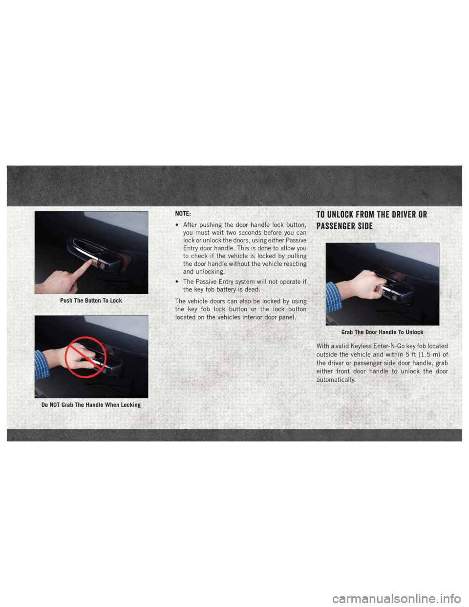
• After pushing the door handle lock button,you must wait two seconds before you can
lock or unlock the doors, using either Passive
Entry door handle. This is done to allow you
to check if the vehicle is locked by pulling
the door handle without the vehicle reacting
and unlocking.
• The Passive Entry system will not operate if the key fob battery is dead.
The vehicle doors can also be locked by using
the key fob lock button or the lock button
located on the vehicles interior door panel.To Unlock From The Driver Or
Passenger Side
With a valid Keyless Enter-N-Go key fob located
outside the vehicle and within 5 ft (1.5 m) of
the driver or passenger side door handle, grab
either front door handle to unlock the door
automatically.
Push The Button To Lock
Do NOT Grab The Handle When Locking
Grab The Door Handle To Unlock
Page 4 of 16

For further information, and applicable warn-
ings and cautions, please refer to the Owner’s
Manual at www.mopar.com/en-us/care/
owners-manual.html (U.S. Residents) or
www.owners.mopar.ca (Canadian Residents).Keyless Enter-N-Go — Ignition
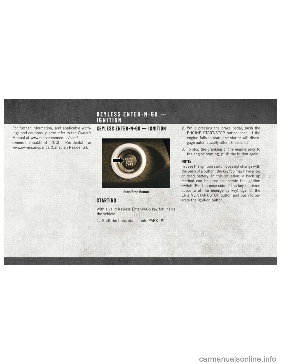
Starting
With a valid Keyless Enter-N-Go key fob inside
the vehicle:
1. Shift the transmission into PARK (P).2. While pressing the brake pedal, push the
ENGINE START/STOP button once. If the
engine fails to start, the starter will disen-
gage automatically after 10 seconds.
3. To stop the cranking of the engine prior to the engine starting, push the button again.
NOTE:
In case the ignition switch does not change with
the push of a button, the key fob may have a low
or dead battery. In this situation, a back up
method can be used to operate the ignition
switch. Put the nose side of the key fob (side
opposite of the emergency key) against the
ENGINE START/STOP button and push to op-
erate the ignition button.
Start/Stop Button
KEYLESS ENTER-N-GO —
IGNITION
Page 6 of 16

NOTE:
• Driving conditions (altitude, vehicle speed,load, etc.) will effect the amount of DEF that
is used in your vehicle.
• Another factor is that outside temperature can affect DEF consumption. In cold condi-
tions, 12° F (-11° C) and below, the DEF
gauge needle can stay on a fixed position
and may not move for extended periods of
time. This is a normal function of the sys-
tem.
• Since DEF will begin to freeze at 12°F (-11°C), your vehicle is equipped with an
automatic DEF heating system. This allows
the DEF injection system to operate properly
at temperatures below 12°F (-11°C). If your
vehicle is not in operation for an extended
period of time with temperatures below 12°F
(-11°C), the DEF in the tank may freeze. If
the tank is overfilled and freezes, it could be
damaged. Therefore, do not overfill the DEF
tank. Extra care should be taken when filling
with portable containers to avoid overfilling.
Note the level of the DEF gauge in your
instrument cluster. On pickup applications, you may safely add a maximum of 2 gallons
(7.5 liters) of DEF from portable containers
when your DEF gauge is reading ½ full. On
Chassis Cab applications, a maximum of
2 gallons (7.5 liters) may be added when the
DEF gauge is reading ¾ full.
• There is an electric heater inside the DEF tank that automatically works when neces-
sary. And if the DEF supply does freeze, the
truck will operate normally until it thaws.
• Ensure the DEF cap is reinstalled prior to filling vehicle with diesel fuel to avoid spill-
ing diesel fuel into the DEF Filler.
AUXILIARY SWITCHES
There can be up to five auxiliary switches lo-
cated in the lower switch bank of the instru-
ment panel, which can all be used to power
various electronic devices and PTO (Power Take
Off) – if equipped. Connections to the switches
are found under the hood in the connectors
attached to the auxiliary Power Distribution
Center. The system has the ability to configure the
functionality of the auxiliary switches via the
Instrument Cluster Display. All switches can
now be configured for ignition or battery power,
saving or not saving the state across a key cycle,
and momentary or latching switch operation.
For further information on using the auxiliary
switches, please refer to the Ram Body Builders
Guide by accessing
www.rambodybuilder.com
and choosing the appropriate links.
For general questions on upfitting commercial
vehicles, including:
• Loose rear park assist installation
• Programmable auxiliary switches
• PTO (Power Take Off) system
• Wiring diagrams
• Vehicle dimensions
• Snow plow installation
• Weight charts and trailer towing
Please consult the Body Builders Guide at
www.rambodybuilder.com.