instrument panel Ram 4500 Chassis Cab 2018 Owner's Manual
[x] Cancel search | Manufacturer: RAM, Model Year: 2018, Model line: 4500 Chassis Cab, Model: Ram 4500 Chassis Cab 2018Pages: 298, PDF Size: 5.88 MB
Page 43 of 298
IconDescription
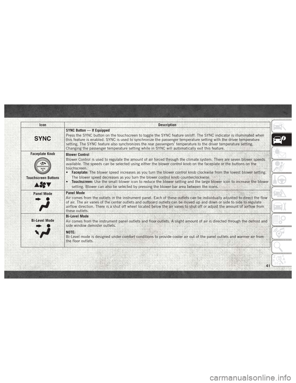
SYNC Button — If Equipped
Press the SYNC button on the touchscreen to toggle the SYNC feature on/off. The SYNC indicator is illuminated when
this feature is enabled. SYNC is used to synchronize the passenger temperature setting with the driver temperature
setting. The SYNC feature also synchronizes the rear passengers’ temperature to the driver temperature setting.
Changing the passenger temperature setting while in SYNC will automatically exit this feature.
Faceplate Knob
Touchscreen Buttons
Blower Control
Blower Control is used to regulate the amount of air forced through the climate system. There are seven blower speeds
available. The speeds can be selected using either the blower control knob on the faceplate or the buttons on the
touchscreen.
• Faceplate: The blower speed increases as you turn the blower control knob clockwise from the lowest blower setting.
The blower speed decreases as you turn the blower control knob counterclockwise.
• Touchscreen:
Use the small blower icon to reduce the blower setting and the large blower icon to increase the blower
setting. Blower can also be selected by pressing the blower bar area between the icons.
Panel Mode
Panel Mode
Air comes from the outlets in the instrument panel. Each of these outlets can be individually adjusted to direct the flow
of air. The air vanes of the center outlets and outboard outlets can be moved up and down or side to side to regulate
airflow direction. There is a shut off wheel located below the air vanes to shut off or adjust the amount of airflow from
these outlets.
Bi-Level Mode
Bi-Level Mode
Air comes from the instrument panel outlets and floor outlets. A slight amount of air is directed through the defrost and
side window demister outlets.
NOTE:
Bi-Level mode is designed under comfort conditions to provide cooler air out of the panel outlets and warmer air from
the floor outlets.
41
Page 47 of 298

1. Pull the hood release lever located belowthe steering wheel at the base of the
instrument panel.
2. Reach into the opening beneath the cen- ter of the hood and push the safety latch
lever to the left to release it, before raising
the hood.
To Close The Hood
Lower the hood to approximately 12 inches
(30 cm) from the engine compartment and
drop it. Make sure that the hood is completely
closed.
WARNING!
Be sure the hood is fully latched before
driving your vehicle. If the hood is not fully
latched, it could open when the vehicle is
in motion and block your vision. Failure to
follow this warning could result in serious
injury or death.
CAUTION!
To prevent possible damage, do not slam
the hood to close it. Use a firm downward
push at the front center of the hood to
ensure that both latches engage.
UNIVERSAL GARAGE DOOR OPENER
(HOMELINK)
• HomeLink replaces up to three hand-held
transmitters that operate devices such as
garage door openers, motorized gates,
lighting or home security systems. The
HomeLink unit is powered by your vehicles
12 Volt battery.
HomeLink Buttons
45
Page 52 of 298

The auxiliary power outlets can be found in
the following locations:
• Lower left and lower right in the center ofthe instrument panel – if equipped with a
column or a eight-speed electronic gear
selector.
• Inside the top storage tray.
• Rear of the center console storage compartment. When the vehicle is turned off, be sure to
unplug any equipment as to not drain the
battery of the vehicle. All accessories con-
nected to the outlet(s) should be removed or
turned off when the vehicle is not in use to
protect the battery against discharge.WARNING!
To avoid serious injury or death:
• Only devices designed for use in this
type of outlet should be inserted into any
12 Volt outlet.
• Do not touch with wet hands.
• Close the lid when not in use and while
driving the vehicle.
• If this outlet is mishandled, it may cause
an electric shock and failure.
CAUTION!
• Many accessories that can be plugged indraw power from the vehicle's battery,
even when not in use (i.e., cellular
phones, etc.). Eventually, if plugged in
long enough, the vehicle's battery will
discharge sufficiently to degrade battery
life and/or prevent the engine from start-
ing.
• Accessories that draw higher power (i.e.,
coolers, vacuum cleaners, lights, etc.),
will discharge the battery even more
Power Outlet — Center Console
Power Outlet — Rear Console
GETTING TO KNOW YOUR VEHICLE
50
Page 53 of 298

CAUTION!
quickly. Only use these intermittently
and with greater caution.
• After the use of high power draw acces-
sories, or long periods of the vehicle not
being started (with accessories still
plugged in), the vehicle must be driven a
sufficient length of time to allow the
generator to recharge the vehicle's bat-
tery.
Power Inverter — If Equipped
A 115 or 230 Volt (150 Watts Maximum)
outlet is located on the center stack of the
instrument panel, to the right of the radio.
This outlet can power cellular phones, elec-
tronics and other low power devices requiring
power up to 150 Watts. Certain high-end
video game consoles will exceed this power
limit, as will most power tools. The power inverter is designed with built-in
overload protection. If the power rating of
150 Watts is exceeded, the power inverter
will automatically shut down. Once the elec-
trical device has been removed from the out-
let the inverter should automatically reset.
To turn on the power outlet, simply plug in the
device. The outlet automatically turns off
when the device is unplugged.
NOTE:
• The Power Inverter will only turn on if the
ignition is in the ACC or ON/RUN position
• Due to built-in overload protection, the power inverter will shut down if the power
rating is exceeded.
WARNING!
To avoid serious injury or death:
• Do not insert any objects into the
receptacles.
• Do not touch with wet hands.
• Close the lid when not in use.
• If this outlet is mishandled, it may cause
an electric shock and failure.
Power Inverter
51
Page 55 of 298

GETTING TO KNOW YOUR INSTRUMENT PANEL
INSTRUMENT CLUSTER DISPLAY.....54
Instrument Cluster Display Controls ....54
Diesel Messages And Warnings —
6.7L Cummins Diesel Engine ........55
Oil Life Reset .................59
Instrument Cluster Display
Programmable Features ...........59
WARNING LIGHTS AND MESSAGES ....61
Red Warning Lights..............61
Yellow Warning Lights ............63
Yellow Indicator Lights ............67
Green Indicator Lights ............68
White Indicator Lights ............68
Blue Indicator Lights .............68
ONBOARD DIAGNOSTIC SYSTEM —
OBDII .....................69
Onboard Diagnostic System (OBD II)
Cybersecurity.................69
GETTING TO KNOW YOUR INSTRUMENT PANEL
53
Page 56 of 298
INSTRUMENT CLUSTER DISPLAY
Your vehicle may be equipped with an instru-
ment cluster display, which offers useful in-
formation to the driver. With the ignition in
the STOP/OFF mode, opening/closing of a
door will activate the display for viewing, and
display the total miles, or kilometers, in the
odometer. Your instrument cluster display is
designed to display important information
about your vehicle’s systems and features.
Using a driver interactive display located on
the instrument panel, your instrument clus-
ter display can show you how systems are
working and give you warnings when they are
not. The steering wheel mounted controls
allow you to scroll through the main menus
and submenus. You can access the specific
information you want and make selections
and adjustments.
Instrument Cluster Display
Controls
The instrument cluster display features a
driver-interactive display that is located in
the instrument cluster.
The instrument cluster display menu items
may consist of the following:
• Speedometer
• Vehicle Info
• Fuel Economy Info
• Trip A
• Trip B
• Audio
• Trailer Tow
• Stored Messages
• Screen Setup
• Vehicle Settings (Not Equipped with aUconnect touchscreen radio) The system allows the driver to select infor-
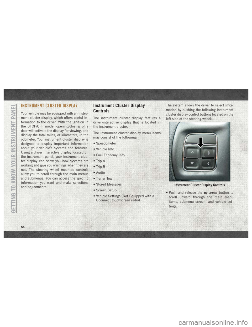
mation by pushing the following instrument
cluster display control buttons located on the
left side of the steering wheel:
• Push and release the
uparrow button to
scroll upward through the main menu
items, submenu screen, and vehicle set-
tings.
Instrument Cluster Display Controls
GETTING TO KNOW YOUR INSTRUMENT PANEL
54
Page 58 of 298

system and allow your Cummins diesel en-
gine and exhaust after-treatment system to
remove the trapped PM and restore the sys-
tem to normal operating condition.
•Exhaust System — Regeneration In Process
Exhaust Filter XX% Full — Indicates that the
Diesel Particulate Filter (DPF) is self-
cleaning. Maintain your current driving
condition until regeneration is completed.
• Exhaust System — Regeneration Completed
— This message indicates that the Diesel
Particulate Filter (DPF) self-cleaning is
completed. If this message is displayed,
you will hear one chime to assist in alerting
you of this condition.
• Exhaust Service Required — See Dealer Now
— This message indicates regeneration has
been disabled due to a system malfunction.
At this point the engine Powertrain Control
Module (PCM) will register a fault code, the
instrument panel will display a MIL light.CAUTION!
See your authorized dealer, as damage to
the exhaust system could occur soon with
continued operation.
• Exhaust Filter Full — Power Reduced See
Dealer — This message indicates the PCM
has derated the engine to limit the likeli-
hood of permanent damage to the after-
treatment system. If this condition is not
corrected and a dealer service is not per-
formed, extensive exhaust after-treatment
damage can occur. To correct this condition
it will be necessary to have your vehicle
serviced by your local authorized dealer.
NOTE:
Failing to follow the oil change indicator,
changing your oil and resetting the oil change
indicator by 0 miles remaining will prevent
the diesel exhaust filter from performing it's
cleaning routine. This will shortly result in a
Malfunction Indicator Light (MIL) and re-
duced engine power. Only an authorized
dealer will be able to correct this condition.
CAUTION!
See your authorized dealer, as damage to
the exhaust system could occur soon with
continued operation.
Cold Ambient Derate Mode Messages
The vehicle will display messages when a
derate (engine power reduction) is activated
to protect the turbocharger during engine
start up in cold ambient temperatures.
• Engine Power Reduced During Warmup —
This message will display during start up
when the ambient temperature is between
10° F (-12° C) and -10° F (-23° C).
• Engine Power Reduced Up To 30 Sec (Sec-
onds) During Warmup — This message will
display during start up when the ambient
temperature is between -10° F (-23° C) and
-25 F (-32° C).
• Engine Power Reduced Up To 2 Min (Minutes)
During Warmup — This message will display
during start up when the ambient tempera-
ture is -25° F (-32° C) and below.
GETTING TO KNOW YOUR INSTRUMENT PANEL
56
Page 60 of 298
5 MPH (8 km/H) if the DEF system is not
serviced within less than 200 miles (322 km)
of the fault being detected.
When the DEF system needs to be serviced
the following warnings will display:
•Service DEF System See Dealer — This mes-
sage will display when the fault is initially
detected, each time the vehicle is started,
and periodically during driving. The mes-
sage will be accompanied by a single
chime. We recommend you drive to your
nearest authorized dealer and have your
vehicle serviced as soon as possible.
• 5 MPH Max Speed in 150 mi Service DEF
System See Dealer — This message will
display if the DEF system has not been
serviced after the “Service DEF System –
See Dealer” message is displayed. This
message will continuously display until the
mileage counter reaches zero, and will be
accompanied by a periodic chime. The
message will continue to countdown until it
reaches zero unless the vehicle is serviced.
We recommend you drive to your nearest
authorized dealer and have your vehicle
serviced immediately. NOTE:
Under some circumstances this mileage
counter may start with a value of less than
150 miles (241 km). For example, if recur-
ring faults are detected in a time interval of
less than 40 hours, the counter may restart
at the value where it stopped when a previ-
ous fault was temporarily remedied, or at a
minimum of 50 miles (80 km).
•
5 MPH Max Speed on Restart, Long Idle or
Refuel Service DEF See Dealer — This mes-
sage will continuously display when the
mileage counter reaches zero, and will be
accompanied by a periodic chime.
The vehicle will only be capable of a maxi-
mum speed of 5 MPH upon the first of the
following conditions to occur: – If the vehicle is shutoff and restarted.
– If the vehicle is idled for an extendedperiod of time, approximately one hour
or greater.
– If the system detects that the level of fuel in the tank has increased. •
5 MPH Max Speed Service DEF System See
Dealer — This message will continuously
display, and will be accompanied by a pe-
riodic chime. Although the vehicle can be
started and placed in gear, the vehicle will
only operate at a maximum speed of
5 MPH. Your vehicle will require towing,
see your authorized dealer for service.
NOTE:
When this message is displayed, the engine
can still be started. However, the vehicle
will only operate at a maximum speed of
5 MPH.
• Incorrect DEF Detected See Dealer — This
message will display when the fault is ini-
tially detected, each time the vehicle is
started, and periodically during driving.
The message will be accompanied by a
single chime. We recommend you drive to
your nearest authorized dealer and have
your vehicle serviced as soon as possible.
RAM Active Air System
Your vehicle is equipped with an advanced
Ram Active Air system that provides en-
hanced performance, especially when towingGETTING TO KNOW YOUR INSTRUMENT PANEL
58
Page 62 of 298
Instrument Cluster Display Programmable Features
The instrument cluster display can be used to view or change the following settings. Push theupordown arrow button until System Setup
displays, then push the rightarrow button. Scroll through the settings using the upordown arrow button. Push the rightarrow button to change
the setting. Push the leftarrow button to scroll back to a previous menu or sub menu.
• Language Select • Remote Start Comfort System
• Units • Easy Exit Seat
• ParkSense • Key Off Power Delay
• Tilt Mirror In Reverse • Commercial Settings
• Rain Sensing Wipers • Air Suspension Display Alerts
• Hill Start Assist • Aero Ride Height Mode
• Headlights Off Delay • Tire/Jack Mode
• Illuminated Approach • Transport Mode
• Headlights On With Wipers • Wheel Alignment Mode
• Automatic Highbeams • Horn With Remote Lower
• Flash Lights With Lock • Lights With Remote Lower
• Auto Lock Doors • Trailer Select
• Auto Unlock Doors • Brake Type
• Sound Horn With Remote Start • Trailer Name
• Sound Horn With Remote Lock • Compass Variance
• Remote Unlock Sequence • Calibrate Compass
• Key Fob Linked To Memory • Fuel Saver Display
• Passive Entry • Park Assist Front Chime Volume
• Park Assist Rear Chime Volume
GETTING TO KNOW YOUR INSTRUMENT PANEL
60
Page 64 of 298
WARNING!
Have the vehicle checked immediately.
Vehicles equipped with the Anti-Lock Brake
System (ABS) are also equipped with Elec-
tronic Brake Force Distribution (EBD). In the
event of an EBD failure, the Brake Warning
Light will turn on along with the ABS Light.
Immediate repair to the ABS system is re-
quired.
Operation of the Brake Warning Light can be
checked by turning the ignition switch from
the OFF position to the ON/RUN position.
The light should illuminate for approximately
two seconds. The light should then turn off
unless the parking brake is applied or a brake
fault is detected. If the light does not illumi-
nate, have the light inspected by your autho-
rized dealer.
The light also will turn on when the parking
brake is applied with the ignition switch in
the ON/RUN position. NOTE:
This light shows only that the parking brake is
applied. It does not show the degree of brake
application.
— Battery Charge Warning Light
This light illuminates when the battery is not
charging properly. If it stays on while the
engine is running, there may be a malfunc-
tion with the charging system. Contact your
authorized dealer as soon as possible.
This indicates a possible problem with the
electrical system or a related component.
— Door Open Warning Light
This indicator will illuminate when a door is
ajar/open and not fully closed.
NOTE:
If the vehicle is moving there will also be a
single chime.
— Electronic Throttle Control (ETC)
Warning Light
This light informs you of a problem with the
Electronic Throttle Control (ETC) system. If a
problem is detected while the vehicle is run- ning, the light will either stay on or flash
depending on the nature of the problem.
Cycle the ignition when the vehicle is safely
and completely stopped and the transmission
is placed in the PARK position. The light
should turn off. If the light remains on with
the vehicle running, your vehicle will usually
be drivable; however, see an authorized
dealer for service as soon as possible.
NOTE:
This light may turn on if the accelerator and
brake pedals are pressed at the same time.
If the light continues to flash when the ve-
hicle is running, immediate service is re-
quired and you may experience reduced per-
formance, an elevated/rough idle, or engine
stall and your vehicle may require towing.
The light will come on when the ignition is
placed in the ON/RUN or ACC/ON/RUN posi-
tion and remain on briefly as a bulb check. If
the light does not come on during starting,
have the system checked by an authorized
dealer.GETTING TO KNOW YOUR INSTRUMENT PANEL
62