oil temperature Ram 4500 Chassis Cab 2018 User Guide
[x] Cancel search | Manufacturer: RAM, Model Year: 2018, Model line: 4500 Chassis Cab, Model: Ram 4500 Chassis Cab 2018Pages: 298, PDF Size: 5.88 MB
Page 58 of 298

system and allow your Cummins diesel en-
gine and exhaust after-treatment system to
remove the trapped PM and restore the sys-
tem to normal operating condition.
•Exhaust System — Regeneration In Process
Exhaust Filter XX% Full — Indicates that the
Diesel Particulate Filter (DPF) is self-
cleaning. Maintain your current driving
condition until regeneration is completed.
• Exhaust System — Regeneration Completed
— This message indicates that the Diesel
Particulate Filter (DPF) self-cleaning is
completed. If this message is displayed,
you will hear one chime to assist in alerting
you of this condition.
• Exhaust Service Required — See Dealer Now
— This message indicates regeneration has
been disabled due to a system malfunction.
At this point the engine Powertrain Control
Module (PCM) will register a fault code, the
instrument panel will display a MIL light.CAUTION!
See your authorized dealer, as damage to
the exhaust system could occur soon with
continued operation.
• Exhaust Filter Full — Power Reduced See
Dealer — This message indicates the PCM
has derated the engine to limit the likeli-
hood of permanent damage to the after-
treatment system. If this condition is not
corrected and a dealer service is not per-
formed, extensive exhaust after-treatment
damage can occur. To correct this condition
it will be necessary to have your vehicle
serviced by your local authorized dealer.
NOTE:
Failing to follow the oil change indicator,
changing your oil and resetting the oil change
indicator by 0 miles remaining will prevent
the diesel exhaust filter from performing it's
cleaning routine. This will shortly result in a
Malfunction Indicator Light (MIL) and re-
duced engine power. Only an authorized
dealer will be able to correct this condition.
CAUTION!
See your authorized dealer, as damage to
the exhaust system could occur soon with
continued operation.
Cold Ambient Derate Mode Messages
The vehicle will display messages when a
derate (engine power reduction) is activated
to protect the turbocharger during engine
start up in cold ambient temperatures.
• Engine Power Reduced During Warmup —
This message will display during start up
when the ambient temperature is between
10° F (-12° C) and -10° F (-23° C).
• Engine Power Reduced Up To 30 Sec (Sec-
onds) During Warmup — This message will
display during start up when the ambient
temperature is between -10° F (-23° C) and
-25 F (-32° C).
• Engine Power Reduced Up To 2 Min (Minutes)
During Warmup — This message will display
during start up when the ambient tempera-
ture is -25° F (-32° C) and below.
GETTING TO KNOW YOUR INSTRUMENT PANEL
56
Page 65 of 298
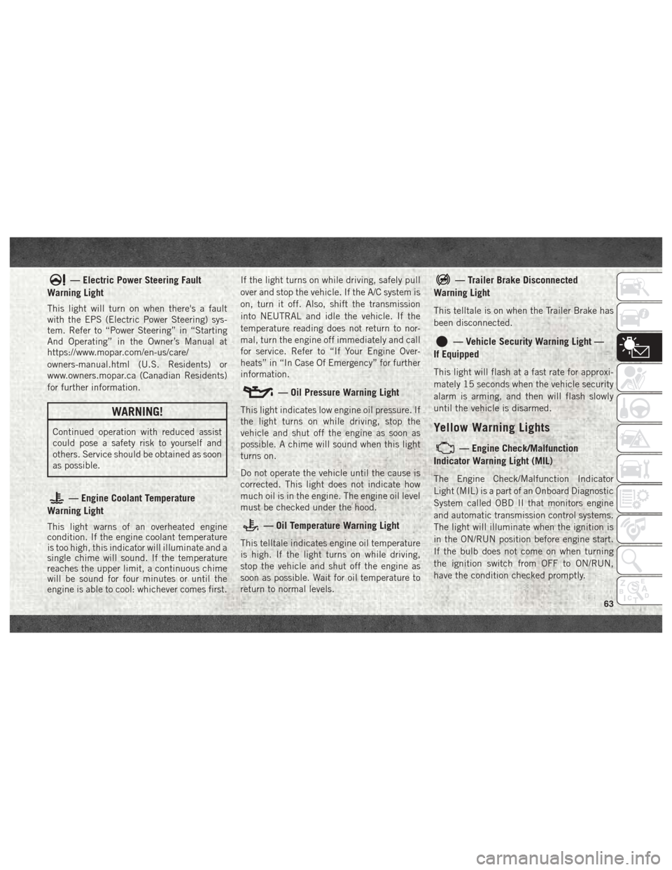
— Electric Power Steering Fault
Warning Light
This light will turn on when there's a fault
with the EPS (Electric Power Steering) sys-
tem. Refer to “Power Steering” in “Starting
And Operating” in the Owner’s Manual at
https://www.mopar.com/en-us/care/
owners-manual.html (U.S. Residents) or
www.owners.mopar.ca (Canadian Residents)
for further information.
WARNING!
Continued operation with reduced assist
could pose a safety risk to yourself and
others. Service should be obtained as soon
as possible.
— Engine Coolant Temperature
Warning Light
This light warns of an overheated engine
condition. If the engine coolant temperature
is too high, this indicator will illuminate and a
single chime will sound. If the temperature
reaches the upper limit, a continuous chime
will be sound for four minutes or until the
engine is able to cool: whichever comes first. If the light turns on while driving, safely pull
over and stop the vehicle. If the A/C system is
on, turn it off. Also, shift the transmission
into NEUTRAL and idle the vehicle. If the
temperature reading does not return to nor-
mal, turn the engine off immediately and call
for service. Refer to “If Your Engine Over-
heats” in “In Case Of Emergency” for further
information.
— Oil Pressure Warning Light
This light indicates low engine oil pressure. If
the light turns on while driving, stop the
vehicle and shut off the engine as soon as
possible. A chime will sound when this light
turns on.
Do not operate the vehicle until the cause is
corrected. This light does not indicate how
much oil is in the engine. The engine oil level
must be checked under the hood.
— Oil Temperature Warning Light
This telltale indicates engine oil temperature
is high. If the light turns on while driving,
stop the vehicle and shut off the engine as
soon as possible. Wait for oil temperature to
return to normal levels.
— Trailer Brake Disconnected
Warning Light
This telltale is on when the Trailer Brake has
been disconnected.
— Vehicle Security Warning Light —
If Equipped
This light will flash at a fast rate for approxi-
mately 15 seconds when the vehicle security
alarm is arming, and then will flash slowly
until the vehicle is disarmed.
Yellow Warning Lights
— Engine Check/Malfunction
Indicator Warning Light (MIL)
The Engine Check/Malfunction Indicator
Light (MIL) is a part of an Onboard Diagnostic
System called OBD II that monitors engine
and automatic transmission control systems.
The light will illuminate when the ignition is
in the ON/RUN position before engine start.
If the bulb does not come on when turning
the ignition switch from OFF to ON/RUN,
have the condition checked promptly.
63
Page 69 of 298
WARNING!
If you continue operating the vehicle when
the Transmission Temperature Warning
Light is illuminated you could cause the
fluid to boil over, come in contact with hot
engine or exhaust components and cause a
fire.
CAUTION!
Continuous driving with the Transmission
Temperature Warning Light illuminated
will eventually cause severe transmission
damage or transmission failure.
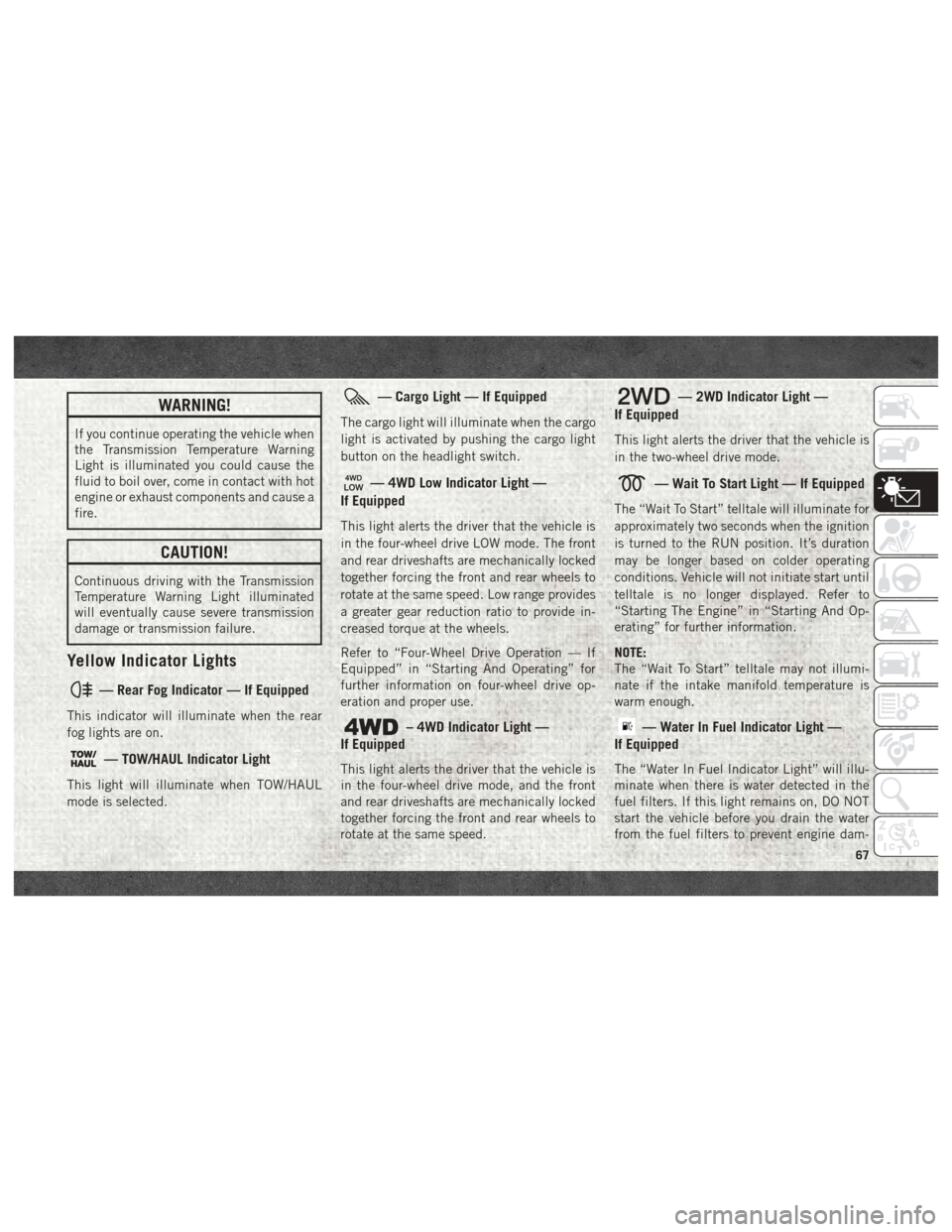
Yellow Indicator Lights
— Rear Fog Indicator — If Equipped
This indicator will illuminate when the rear
fog lights are on.
— TOW/HAUL Indicator Light
This light will illuminate when TOW/HAUL
mode is selected.
— Cargo Light — If Equipped
The cargo light will illuminate when the cargo
light is activated by pushing the cargo light
button on the headlight switch.
— 4WD Low Indicator Light —
If Equipped
This light alerts the driver that the vehicle is
in the four-wheel drive LOW mode. The front
and rear driveshafts are mechanically locked
together forcing the front and rear wheels to
rotate at the same speed. Low range provides
a greater gear reduction ratio to provide in-
creased torque at the wheels.
Refer to “Four-Wheel Drive Operation — If
Equipped” in “Starting And Operating” for
further information on four-wheel drive op-
eration and proper use.
– 4WD Indicator Light —
If Equipped
This light alerts the driver that the vehicle is
in the four-wheel drive mode, and the front
and rear driveshafts are mechanically locked
together forcing the front and rear wheels to
rotate at the same speed.
— 2WD Indicator Light —
If Equipped
This light alerts the driver that the vehicle is
in the two-wheel drive mode.
— Wait To Start Light — If Equipped
The “Wait To Start” telltale will illuminate for
approximately two seconds when the ignition
is turned to the RUN position. It’s duration
may be longer based on colder operating
conditions. Vehicle will not initiate start until
telltale is no longer displayed. Refer to
“Starting The Engine” in “Starting And Op-
erating” for further information.
NOTE:
The “Wait To Start” telltale may not illumi-
nate if the intake manifold temperature is
warm enough.
— Water In Fuel Indicator Light —
If Equipped
The “Water In Fuel Indicator Light” will illu-
minate when there is water detected in the
fuel filters. If this light remains on, DO NOT
start the vehicle before you drain the water
from the fuel filters to prevent engine dam-
67
Page 126 of 298
3. While the "Wait to Start" telltale is on, theinstrument cluster will additionally dis-
play a gauge or bar whose initial length
represents the full "Wait to Start" time
period. Its length will decrease until it
disappears when the "Wait to Start" time
has elapsed.
CAUTION!
If the “Water in Fuel Indicator Light” re-
mains on, DO NOT START engine before
you drain the water from the fuel filters to
avoid engine damage. Refer to “Draining
Fuel/Water Separator Filter” in “Dealer
Service” under “Servicing And Mainte-
nance” for further information.
4.
After the engine “Wait To Start” telltale goes
off, the engine will automatically crank.
CAUTION!
Do not crank engine for more than 15 seconds
at a time or starter motor damage may result.
Turn the ignition switch to the OFF position
and wait at least two minutes for the starter to
cool before repeating start procedure.
5. After engine start-up, check to see that there is oil pressure.
6. Allow the engine to idle about three min- utes until the manifold heaters have com-
pleted the post-heat cycle.
7. Release the parking brake and drive.
NOTE:
• Engine idle speed will automatically in- crease to 1,000 RPM and engage the Vari-
able Geometry Turbocharger at low coolant
temperatures to improve engine warm-up.
• The engine may not automatically crank after the engine "Wait To Start" telltale goes
off if a door or the hood is ajar.
• If the engine stalls, or if the ignition switch is left ON for more than two minutes after
the “Wait To Start Light” goes out, reset the
grid heaters by turning the ignition switch
to the OFF position for at least five seconds
and then back ON. Repeat steps 1 through
7 of “Keyless Enter-N-Go Starting Proce-
dure – Engine Manifold Air Temperature
Below 66° F (19° C).”Extreme Cold Weather
The Cummins diesel engine is equipped with
several features designed to assist cold
weather starting and operation:
• The engine block heater is a resistance
heater installed in the water jacket of the
engine just above and behind the oil filter.
It requires a 110–115 Volt AC electrical
outlet with a grounded, three-wire exten-
sion cord.
NOTE:
The engine block heater cord is a factory
installed option. If your vehicle is not
equipped, heater cords are available from
your authorized Mopar dealer.
• A 12 Volt heater built into the fuel filter housings aid in preventing fuel gelling. It is
controlled by a built-in thermostat.
• A heated intake air system both improves engine starting and reduces the amount of
white smoke generated by a warming
engine.
STARTING AND OPERATING
124
Page 127 of 298
NORMAL OPERATION — 6.7L DIESEL
ENGINE
Observe the following when the engine is
operating.
• All message center lights are off.
• Malfunction Indicator Light (MIL) is off.
• Engine oil pressure is above 10 psi(69 kPa) at idle.
• Voltmeter operation:
The voltmeter may show a gauge fluctuation
at various engine temperatures. This cycling
operation is caused by the post-heat cycle of
the intake manifold heater system. The num-
ber of cycles and the length of the cycling
operation is controlled by the engine control
module. Post-heat operation can run for sev-
eral minutes, and then the electrical system
and voltmeter needle will stabilize.
The cycling action will cause temporary dim-
ming of the headlamps, interior lamps, and
also a noticeable reduction in blower motor
speed.
Cold Weather Precautions
Operation in ambient temperature below
32°F (0°C) may require special consider-
ations. The following charts suggest these
options:
Winter Front Cover Usage
A winter front or cold weather cover is to be
used in ambient temperatures below 32°F
(0°C), especially during extended idle condi-
tions. This cover is equipped with four flaps
for managing total grille opening in varying
ambient temperatures. If a winter front or
cold weather cover is to be used the flaps
should be left in the full open position to
allow air flow to the charge air cooler and
automatic transmission oil cooler. When am-
bient temperatures drop below 0°F (-17°C)
the four flaps need to be closed. A suitable
cold weather cover is available from your
Mopar dealer.
Engine Idling
Avoid prolonged idling, long periods of idling
may be harmful to your engine because com-
bustion chamber temperatures can drop so low that the fuel may not burn completely.
Incomplete combustion allows carbon and
varnish to form on piston rings, engine valves,
and injector nozzles. Also, the unburned fuel
can enter the crankcase, diluting the oil and
causing rapid wear to the engine.
If the engine is allowed to idle or the truck is
driven on low engine speed drive cycles for
more than 2 hours, the system will automati-
cally enter an emissions operating mode that
will increase the engine idle speed to
900 RPM (1050 RPM for Chassis Cab).
While in this mode, which is designed to help
maintain the diesel particulate filter, the en-
gine idle speed will return to normal when the
brake pedal is applied. A small change in
engine tone or a slight change in engine
performance while accelerating may also be
noticeable at speeds below 20 mph
(32 kmh). This operating mode may last for
up to an hour of idle time, or around 20 min-
utes of driving time.
Your truck may have been ordered with an
optional voltage monitoring idle up feature. If
a load is placed on the electrical system while
the truck is in park, this feature will attempt
125
Page 128 of 298

to maintain normal system voltage by auto-
matically increasing engine idle speed. You
may notice several consecutive increases in
idle speed, up to a maximum of 1450 RPM,
as the system will attempt to utilize the
smallest increase in idle speed necessary to
maintain normal system voltage. The idle
speed will return to normal when either the
electrical load is removed, or when the brake
pedal is applied.
NOTE:
For instrument cluster display messages re-
lated to the vehicle's exhaust system, refer to
“Instrument Cluster Display” in “Getting To
Know Your Instrument Panel” for further in-
formation.
Idle-Up Feature — Automatic Transmission
Only
The driver-controlled high idle speed feature
will help increase cylinder temperatures and
provide additional cab heat, however, exces-
sive idling may still cause the exhaust after-
treatment system to not properly regenerate.
Extended periods of idle time should be
avoided.The Idle-Up feature uses the speed control
switches to increase engine idle speed and
quickly warm the vehicle's interior.
1. With the transmission in PARK, the park-
ing brake applied, and the engine run-
ning, push the speed control switch to the
ON position, then push the SET switch.
2. The engine RPM will go up to 1100 RPM. To increase the RPM, push and hold the
ACCEL/RESUME switch and the idle
speed will increase to approximately
1500 RPM. To decrease the RPM, push
and hold the DECEL switch and the idle
speed will decrease to approximately
1100 RPM.
3. To cancel the Idle–Up feature, either push the CANCEL switch, push the ON/OFF
switch, or press the brake pedal.Stopping The Engine
Idle the engine a few minutes before routine
shutdown. After full load operation, idle the
engine three to five minutes before shutting it
down. This idle period will allow the lubricat- ing oil and coolant to carry excess heat away
from the combustion chamber, bearings, in-
ternal components, and turbocharger. This is
especially important for turbocharged,
charge air-cooled engines.
NOTE:
• During engine shut down on vehicles
equipped with manual transmissions, it is
normal for the diesel engine to resonate
heavily for a moment during engine shut
off. When the engine is connected to a
manual transmission, this resonance
causes load gear rattle from the transmis-
sion. This is commonly referred to as “shut
down rattle.” The manufacturer recom-
mends performing engine shut down with
the clutch pedal pushed to the floor (clutch
disengaged). When engine shut down is
performed in this manner the rattle is re-
duced (not eliminated).
• Refer to the following chart for proper en- gine shutdown.
STARTING AND OPERATING
126
Page 129 of 298

Driving ConditionLoadTurbocharger Temperature Idle Time (min.)
Before Engine Shutdown
Stop and Go EmptyCoolLess than One
Stop and Go Medium -One
Highway Speeds MediumWarmTwo
City Traffic Maximum GCWR -Three
Highway Speeds Maximum GCWR -Four
Uphill Grade Maximum GCWR HotFive
ENGINE BREAK-IN
RECOMMENDATIONS — GASOLINE
ENGINE
A long break-in period is not required for the
engine and drivetrain (transmission and axle)
in your vehicle.
Drive moderately during the first 300 miles
(500 km). After the initial 60 miles
(100 km), speeds up to 50 or 55 mph (80 or
90 km/h) are desirable.
While cruising, brief full-throttle acceleration
within the limits of local traffic laws contrib-
utes to a good break-in. Wide-open throttle
acceleration in low gear can be detrimental
and should be avoided. The engine oil installed in the engine at the
factory is a high-quality energy conserving
type lubricant. Oil changes should be consis-
tent with anticipated climate conditions un-
der which vehicle operations will occur. For
the recommended viscosity and quality
grades, refer to “Fluids And Lubricants” in
“Technical Specifications”.
CAUTION!
Never use Non-Detergent Oil or Straight
Mineral Oil in the engine or damage may
result.
NOTE:
A new engine may consume some oil during
its first few thousand miles (kilometers) of
operation. This should be considered a nor-
mal part of the break-in and not interpreted
as a problem. Please check your oil level with
the engine oil indicator often during the
break in period. Add oil as required.
ENGINE BREAK-IN
RECOMMENDATIONS — 6.7L DIESEL
The Cummins turbocharged diesel engine
does not require a break-in period due to its
construction. Normal operation is allowed,
providing the following recommendations are
followed:
127
Page 160 of 298
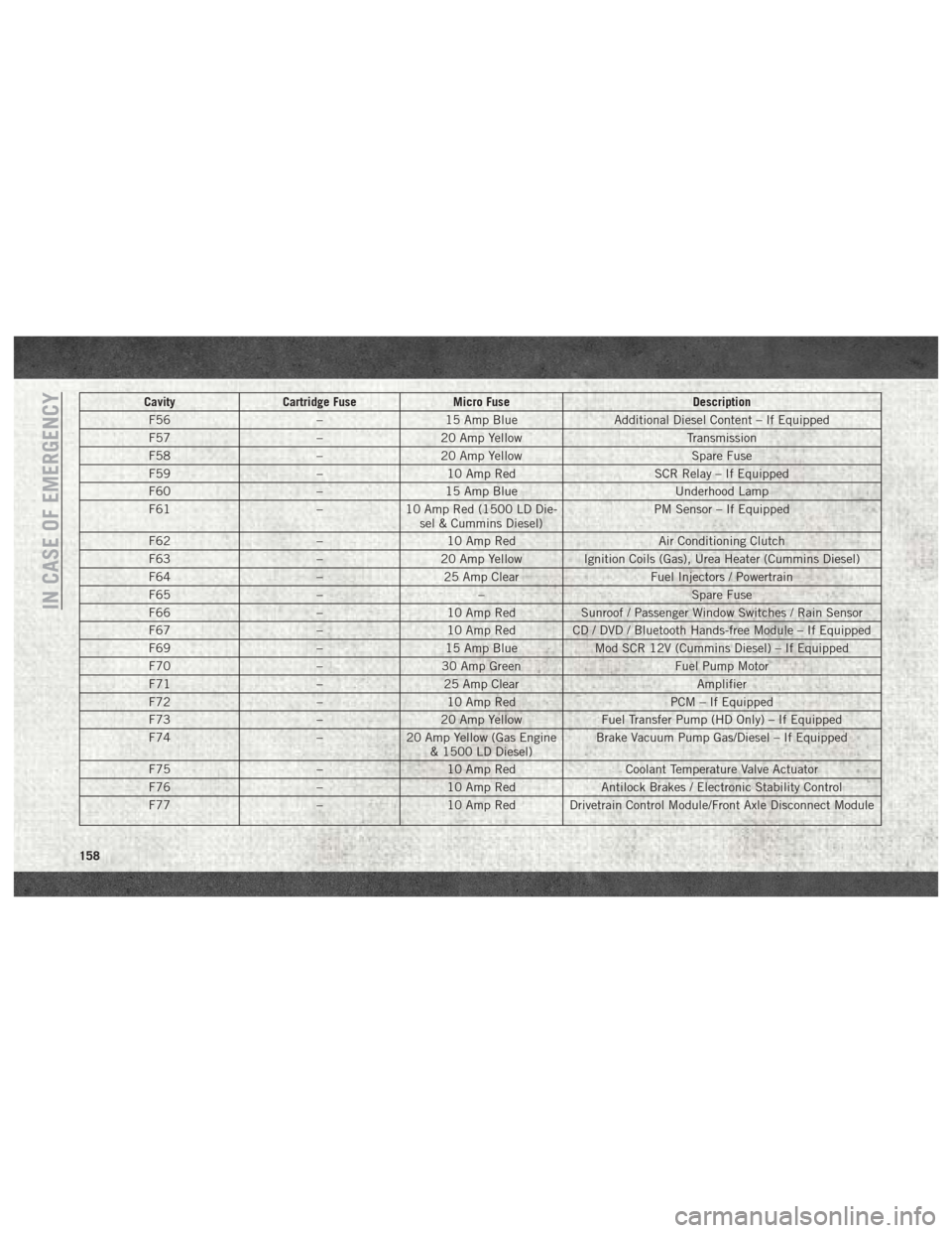
CavityCartridge Fuse Micro Fuse Description
F56 –15 Amp Blue Additional Diesel Content – If Equipped
F57 –20 Amp Yellow Transmission
F58 –20 Amp Yellow Spare Fuse
F59 –10 Amp Red SCR Relay – If Equipped
F60 –15 Amp Blue Underhood Lamp
F61 –10 Amp Red (1500 LD Die-
sel & Cummins Diesel) PM Sensor – If Equipped
F62 –10 Amp Red Air Conditioning Clutch
F63 –20 Amp Yellow Ignition Coils (Gas), Urea Heater (Cummins Diesel)
F64 –25 Amp Clear Fuel Injectors / Powertrain
F65 –– Spare Fuse
F66 –10 Amp Red Sunroof / Passenger Window Switches / Rain Sensor
F67 –10 Amp Red CD / DVD / Bluetooth Hands-free Module – If Equipped
F69 –15 Amp Blue Mod SCR 12V (Cummins Diesel) – If Equipped
F70 –30 Amp Green Fuel Pump Motor
F71 –25 Amp Clear Amplifier
F72 –10 Amp Red PCM – If Equipped
F73 –20 Amp Yellow Fuel Transfer Pump (HD Only) – If Equipped
F74 –20 Amp Yellow (Gas Engine
& 1500 LD Diesel) Brake Vacuum Pump Gas/Diesel – If Equipped
F75 –10 Amp Red Coolant Temperature Valve Actuator
F76 –10 Amp Red Antilock Brakes / Electronic Stability Control
F77 –10 Amp Red Drivetrain Control Module/Front Axle Disconnect Module
IN CASE OF EMERGENCY
158
Page 175 of 298
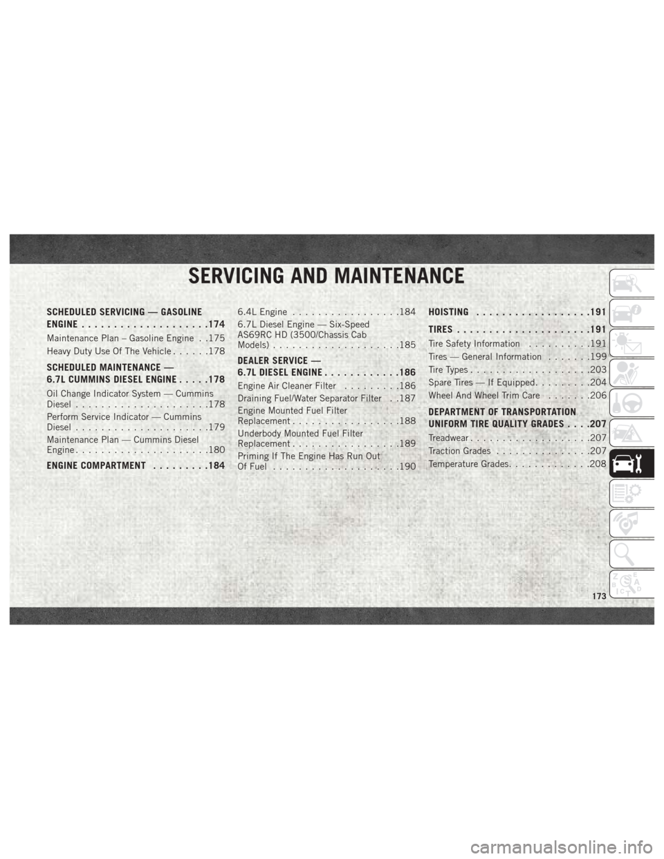
SERVICING AND MAINTENANCE
SCHEDULED SERVICING — GASOLINE
ENGINE................... .174
Maintenance Plan – Gasoline Engine . .175
Heavy Duty Use Of The Vehicle ......178
SCHEDULED MAINTENANCE —
6.7L CUMMINS DIESEL ENGINE.....178
Oil Change Indicator System — Cummins
Diesel.....................178
Perform Service Indicator — Cummins
Diesel .....................179
Maintenance Plan — Cummins Diesel
Engine .....................180
ENGINE COMPARTMENT .........184
6.4L Engine.................184
6.7L Diesel Engine — Six-Speed
AS69RC HD (3500/Chassis Cab
Models) ....................185
DEALER SERVICE —
6.7L DIESEL ENGINE ............186
Engine Air Cleaner Filter .........186
Draining Fuel/Water Separator Filter . .187
Engine Mounted Fuel Filter
Replacement .................188
Underbody Mounted Fuel Filter
Replacement .................189
Priming If The Engine Has Run Out
Of Fuel ....................190
HOISTING ................. .191
TIRES .................... .191
Tire Safety Information..........191
Tires — General Information .......199
Tire Types ...................203
Spare Tires — If Equipped .........204
Wheel And Wheel Trim Care .......206
DEPARTMENT OF TRANSPORTATION
UNIFORM TIRE QUALITY GRADES . . . .207
Treadwear...................207
Traction Grades ...............207
Temperature Grades .............208
SERVICING AND MAINTENANCE
173
Page 176 of 298
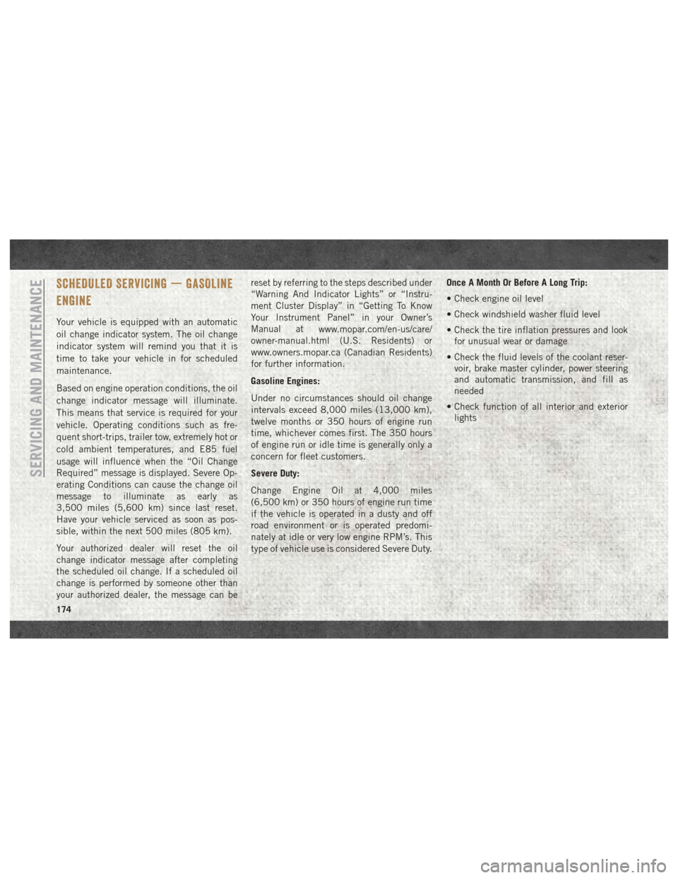
SCHEDULED SERVICING — GASOLINE
ENGINE
Your vehicle is equipped with an automatic
oil change indicator system. The oil change
indicator system will remind you that it is
time to take your vehicle in for scheduled
maintenance.
Based on engine operation conditions, the oil
change indicator message will illuminate.
This means that service is required for your
vehicle. Operating conditions such as fre-
quent short-trips, trailer tow, extremely hot or
cold ambient temperatures, and E85 fuel
usage will influence when the “Oil Change
Required” message is displayed. Severe Op-
erating Conditions can cause the change oil
message to illuminate as early as
3,500 miles (5,600 km) since last reset.
Have your vehicle serviced as soon as pos-
sible, within the next 500 miles (805 km).
Your authorized dealer will reset the oil
change indicator message after completing
the scheduled oil change. If a scheduled oil
change is performed by someone other than
your authorized dealer, the message can bereset by referring to the steps described under
“Warning And Indicator Lights” or “Instru-
ment Cluster Display” in “Getting To Know
Your Instrument Panel” in your Owner’s
Manual at
www.mopar.com/en-us/care/
owner-manual.html (U.S. Residents) or
www.owners.mopar.ca (Canadian Residents)
for further information.
Gasoline Engines:
Under no circumstances should oil change
intervals exceed 8,000 miles (13,000 km),
twelve months or 350 hours of engine run
time, whichever comes first. The 350 hours
of engine run or idle time is generally only a
concern for fleet customers.
Severe Duty:
Change Engine Oil at 4,000 miles
(6,500 km) or 350 hours of engine run time
if the vehicle is operated in a dusty and off
road environment or is operated predomi-
nately at idle or very low engine RPM’s. This
type of vehicle use is considered Severe Duty. Once A Month Or Before A Long Trip:
• Check engine oil level
• Check windshield washer fluid level
• Check the tire inflation pressures and look
for unusual wear or damage
• Check the fluid levels of the coolant reser- voir, brake master cylinder, power steering
and automatic transmission, and fill as
needed
• Check function of all interior and exterior lights
SERVICING AND MAINTENANCE
174