spare wheel Ram 4500 Chassis Cab 2018 User Guide
[x] Cancel search | Manufacturer: RAM, Model Year: 2018, Model line: 4500 Chassis Cab, Model: Ram 4500 Chassis Cab 2018Pages: 298, PDF Size: 5.88 MB
Page 67 of 298
— Tire Pressure Monitoring System
(TPMS) Warning Light
The warning light switches on and a message
is displayed to indicate that the tire pressure
is lower than the recommended value and/or
that slow pressure loss is occurring. In these
cases, optimal tire duration and fuel con-
sumption may not be guaranteed.
Should one or more tires be in the condition
mentioned above, the display will show the
indications corresponding to each tire in
sequence.
CAUTION!
Do not continue driving with one or more
flat tires as handling may be compro-
mised. Stop the vehicle, avoiding sharp
braking and steering. If a tire puncture
occurs, repair immediately using the dedi-
cated tire repair kit and contact your au-
thorized dealer as soon as possible.
Each tire, including the spare (if provided),
should be checked monthly when cold and
inflated to the inflation pressure recom-
mended by the vehicle manufacturer on the vehicle placard or tire inflation pressure la-
bel. (If your vehicle has tires of a different
size than the size indicated on the vehicle
placard or tire inflation pressure label, you
should determine the proper tire inflation
pressure for those tires.)
As an added safety feature, your vehicle has
been equipped with a tire pressure monitor-
ing system (TPMS) that illuminates a low tire
pressure telltale when one or more of your
tires is significantly under-inflated. Accord-
ingly, when the low tire pressure telltale illu-
minates, you should stop and check your tires
as soon as possible, and inflate them to the
proper pressure. Driving on a significantly
under-inflated tire causes the tire to overheat
and can lead to tire failure. Under-inflation
also reduces fuel efficiency and tire tread
life, and may affect the vehicle’s handling
and stopping ability.
Please note that the TPMS is not a substitute
for proper tire maintenance, and it is the
driver’s responsibility to maintain correct tire
pressure, even if under-inflation has not
reached the level to trigger illumination of the
TPMS low tire pressure telltale.Your vehicle has also been equipped with a
TPMS malfunction indicator to indicate when
the system is not operating properly. The
TPMS malfunction indicator is combined
with the low tire pressure telltale. When the
system detects a malfunction, the telltale will
flash for approximately one minute and then
remain continuously illuminated. This se-
quence will continue upon subsequent ve-
hicle start-ups as long as the malfunction
exists. When the malfunction indicator is
illuminated, the system may not be able to
detect or signal low tire pressure as intended.
TPMS malfunctions may occur for a variety of
reasons, including the installation of replace-
ment or alternate tires or wheels on the ve-
hicle that prevent the TPMS from functioning
properly. Always check the TPMS malfunc-
tion telltale after replacing one or more tires
or wheels on your vehicle to ensure that the
replacement or alternate tires and wheels
allow the TPMS to continue to function
properly.
65
Page 77 of 298
• Signal interference due to electronic de-vices or driving next to facilities emitting
the same radio frequencies as the TPM
sensors.
• Installing aftermarket window tinting that contains materials that may block radio
wave signals.
• Accumulation of snow or ice around the wheels or wheel housings.
• Using tire chains on the vehicle.
• Using wheels/tires not equipped with TPM sensors.
A system fault may occur due to an incorrect
TPM sensor location condition. When a sys-
tem fault occurs due to an incorrect TPM
sensor location, the “Tire Pressure Monitor-
ing Telltale Light” will flash on and off for
75 seconds and then remain on solid. The
system fault will also sound a chime. In
addition, the instrument cluster will display a
“Tire Pressure Temporarily Unavailable”
message in place of the tire pressure display
screen. If the ignition switch is cycled, this
sequence will repeat, providing the system
fault still exists. If the system fault no longer
exists, the “Tire Pressure Monitoring Telltale Light” will no longer flash and the tire pres-
sure display screen will be displayed showing
the tire pressure values the correct locations.
Vehicles With Non Matching Full Size Spare Or
Compact Spare
• The non matching full size spare or com-
pact spare tire does not have a TPM sensor.
Therefore, the TPMS will not monitor the
pressure in the non matching full size spare
or compact spare tire.
• If you install the non matching full size spare or compact spare tire in place of a
road tire that has a pressure below the
low-pressure warning limit, upon the next
ignition switch cycle, the TPM Telltale
Light and a “LOW TIRE” message will re-
main ON and a chime will sound. In addi-
tion, the graphic in the instrument cluster
will still display a pressure value in a differ-
ent color.
• After driving the vehicle for up to 20 min- utes above 15 mph (24 km/h), the TPM
Telltale Light will flash on and off for
75 seconds and then remain on solid. In
addition, the instrument cluster will display a "SERVICE TPM SYSTEM" message for a
minimum of five seconds and then display
dashes (- -) in place of the pressure value.
• For each subsequent ignition switch cycle, a chime will sound, the TPM Telltale Light
will flash on and off for 75 seconds and
then remain on solid, and the instrument
cluster will display a "SERVICE TPM SYS-
TEM" message for a minimum of five sec-
onds and then display dashes (- -) in place
of the pressure value.
• Once you repair or replace the original road tire and reinstall it on the vehicle in place of
the non matching full size spare or compact
spare, the TPMS will update automatically.
In addition, the TPM Telltale Light will turn
OFF and the graphic in the instrument
cluster will display a new pressure value
instead of dashes (- -), as long as no tire
pressure is below the low-pressure warning
limit in any of the four active road tires. The
vehicle may need to be driven for up to
20 minutes above 15 mph (24 km/h) in
order for the TPMS to receive this
information.
75
Page 119 of 298
WARNING!
control. To prevent SERIOUS INJURY or
DEATH:
• ALWAYS securely attach
your floor
mat using the floor mat fasteners. DO
NOT install your floor mat upside down
or turn your floor mat over. Lightly pull to
confirm mat is secured using the floor
mat fasteners on a regular basis.
• ALWAYS REMOVE THE EXISTING
FLOOR MAT FROM THE VEHICLE
before installing any other floor mat.
NEVER install or stack an additional
floor mat on top of an existing floor mat.
• ONLY install floor mats designed to fit
your vehicle. NEVER install a floor mat
that cannot be properly attached and
secured to your vehicle. If a floor mat
needs to be replaced, only use a FCA
approved floor mat for the specific
make, model, and year of your vehicle.
• ONLY use the driver’s side floor mat on
the driver’s side floor area. To check for
interference, with the vehicle properly
parked with the engine off, fully depress
the accelerator, the brake, and the
WARNING!
clutch pedal (if present) to check for
interference. If your floor mat interferes
with the operation of any pedal, or is not
secure to the floor, remove the floor mat
from the vehicle and place the floor mat
in your trunk.
• ONLY use the passenger’s side floor mat
on the passenger’s side floor area.
• ALWAYS make sure objects cannot fall
or slide into the driver’s side floor area
when the vehicle is moving. Objects can
become trapped under accelerator,
brake, or clutch pedals and could cause
a loss of vehicle control.
• NEVER place any objects under the floor
mat (e.g., towels, keys, etc.). These ob-
jects could change the position of the
floor mat and may cause interference
with the accelerator, brake, or clutch
pedals.
• If the vehicle carpet has been removed
and re-installed, always properly attach
carpet to the floor and check the floor
mat fasteners are secure to the vehicle
carpet. Fully depress each pedal to
WARNING!
check for interference with the accelera-
tor, brake, or clutch pedals then re-
install the floor mats.
• It is recommended to only use mild soap
and water to clean your floor mats. After
cleaning, always check your floor mat
has been properly installed and is se-
cured to your vehicle using the floor mat
fasteners by lightly pulling mat.
Periodic Safety Checks You
Should Make Outside The Vehicle
Tires
Examine tires for excessive tread wear and
uneven wear patterns. Check for stones,
nails, glass, or other objects lodged in the
tread or sidewall. Inspect the tread for cuts
and cracks. Inspect sidewalls for cuts,
cracks, and bulges. Check the wheel bolts for
tightness. Check the tires (including spare)
for proper cold inflation pressure.
117
Page 155 of 298
IN CASE OF EMERGENCY
HAZARD WARNING FLASHERS.....154
BULB REPLACEMENT ...........154
Replacement Bulbs.............154
FUSES.................... .155
Power Distribution Center.........155
JACKING AND TIRE CHANGING .....160
4500/5500 Models.............160
Preparations For Jacking ..........160
Jacking Instructions 4500 And
5500 Series .................161 To Stow The Flat Or Spare —
If Equipped
.................163
Hub Caps/Wheel Covers —
If Equipped .................163
JUMP STARTING ..............164
Preparations For Jump Start ........164
Jump Starting Procedure ..........165
IF YOUR ENGINE OVERHEATS ......166
GEAR SELECTOR OVERRIDE .......167FREEING A STUCK VEHICLE
.......168
TOWING A DISABLED VEHICLE .....169
Two-Wheel Drive Models..........170
Four-Wheel Drive Models ..........170
Emergency Tow Hooks — If Equipped . .171
ENHANCED ACCIDENT RESPONSE SYSTEM
(EARS) ................... .171
EVENT DATA RECORDER (EDR) ......171
IN CASE OF EMERGENCY
153
Page 163 of 298
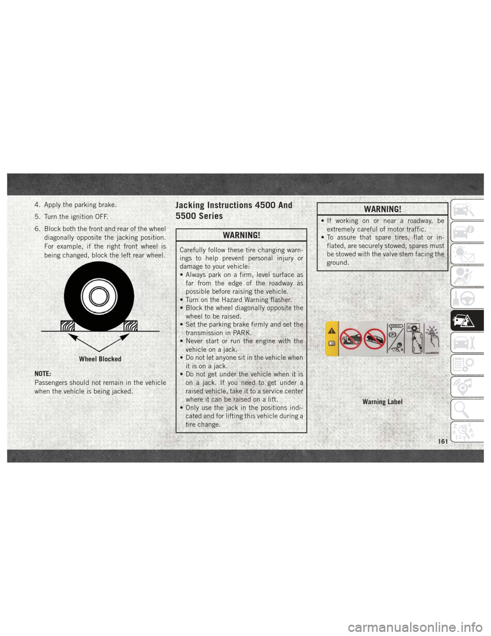
4. Apply the parking brake.
5. Turn the ignition OFF.
6. Block both the front and rear of the wheeldiagonally opposite the jacking position.
For example, if the right front wheel is
being changed, block the left rear wheel.
NOTE:
Passengers should not remain in the vehicle
when the vehicle is being jacked.Jacking Instructions 4500 And
5500 Series
WARNING!
Carefully follow these tire changing warn-
ings to help prevent personal injury or
damage to your vehicle:
• Always park on a firm, level surface as far from the edge of the roadway as
possible before raising the vehicle.
• Turn on the Hazard Warning flasher.
• Block the wheel diagonally opposite the
wheel to be raised.
• Set the parking brake firmly and set the
transmission in PARK.
• Never start or run the engine with the
vehicle on a jack.
• Do not let anyone sit in the vehicle when
it is on a jack.
• Do not get under the vehicle when it is
on a jack. If you need to get under a
raised vehicle, take it to a service center
where it can be raised on a lift.
• Only use the jack in the positions indi-
cated and for lifting this vehicle during a
tire change.
WARNING!
• If working on or near a roadway, beextremely careful of motor traffic.
• To assure that spare tires, flat or in-
flated, are securely stowed, spares must
be stowed with the valve stem facing the
ground.
Wheel Blocked
Warning Label
161
Page 164 of 298
CAUTION!
Do not attempt to raise the vehicle by
jacking on locations other than those indi-
cated in the Jacking Instructions for this
vehicle.
1. If equipped, remove the spare wheel, jack, and tools from storage.
2. Using the lug wrench, loosen, but do not remove, the lug nuts by turning them
counterclockwise one turn while the
wheel is still on the ground.
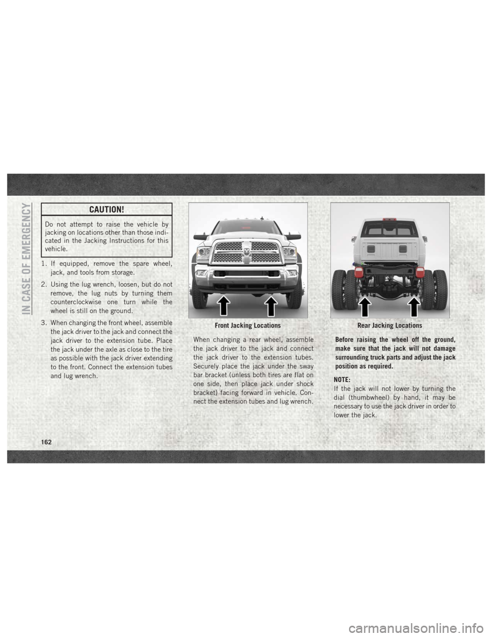
3. When changing the front wheel, assemble the jack driver to the jack and connect the
jack driver to the extension tube. Place
the jack under the axle as close to the tire
as possible with the jack driver extending
to the front. Connect the extension tubes
and lug wrench. When changing a rear wheel, assemble
the jack driver to the jack and connect
the jack driver to the extension tubes.
Securely place the jack under the sway
bar bracket (unless both tires are flat on
one side, then place jack under shock
bracket) facing forward in vehicle. Con-
nect the extension tubes and lug wrench.Before raising the wheel off the ground,
make sure that the jack will not damage
surrounding truck parts and adjust the jack
position as required.
NOTE:
If the jack will not lower by turning the
dial (thumbwheel) by hand, it may be
necessary to use the jack driver in order to
lower the jack.
Front Jacking LocationsRear Jacking Locations
IN CASE OF EMERGENCY
162
Page 165 of 298
4. By rotating the lug wrench clockwise,raise the vehicle until the wheel just
clears the surface.
WARNING!
Raising the vehicle higher than necessary
can make the vehicle less stable. It could
slip off the jack and hurt someone near it.
Raise the vehicle only enough to remove
the tire.
5. Remove the lug nuts and pull the wheel off. Install the spare wheel and lug nuts
with the cone shaped end of the nuts
toward the wheel on single rear wheel
(SRW) models. On dual rear wheel models
(DRW) the lug nuts are a two-piece assem-
bly with a flat face. Lightly tighten the
nuts. To avoid risk of forcing the vehicle
off the jack, do not fully tighten the nuts
until the vehicle has been lowered.
6. Using the lug wrench, finish tightening the nuts using a crisscross pattern. For
the proper lug nut torque specifications
refer to “Wheel And Tire Torque Specifi-
cations” in “Technical Specifications.” If
in doubt about the correct tightness, have them checked with a torque wrench by an
authorized dealer or at a service station.
WARNING!
A loose tire or jack thrown forward in a
collision or hard stop, could endanger the
occupants of the vehicle. Always stow the
jack parts and the spare tire in the places
provided.
7. Install wheel center cap (if equipped) and remove wheel blocks. Do not install
chrome or aluminum wheel center caps
on the spare wheel. This may result in cap
damage.
8. Lower the jack to its fully closed position. If the jack will not lower by turning the
dial (thumbwheel) by hand, it may be
necessary to use the jack driver in order to
lower the jack. Stow the replaced tire,
jack, and tools as previously described.
9. Adjust the tire pressure when possible.
To Stow The Flat Or Spare —
If Equipped
Refer to Upfitters Body Builders Guide for
information on stowing your spare tire (if
equipped).
Hub Caps/Wheel Covers —
If Equipped
The hub caps must be removed before raising
the vehicle off the ground.
CAUTION!
Use extreme caution when removing the
front and rear center caps. Damage can
occur to the center cap and/or the wheel if
screwdriver type tools are used. A pulling
motion, not a pry off motion, is recom-
mended to remove the caps.
For single rear wheel (SRW) models, use the
flat blade on the end of the lug wrench to pull
the hub cap off. Insert the blade end into the
pull off notch and carefully pull the hub cap
off with a back and forth motion.
163
Page 175 of 298
SERVICING AND MAINTENANCE
SCHEDULED SERVICING — GASOLINE
ENGINE................... .174
Maintenance Plan – Gasoline Engine . .175
Heavy Duty Use Of The Vehicle ......178
SCHEDULED MAINTENANCE —
6.7L CUMMINS DIESEL ENGINE.....178
Oil Change Indicator System — Cummins
Diesel.....................178
Perform Service Indicator — Cummins
Diesel .....................179
Maintenance Plan — Cummins Diesel
Engine .....................180
ENGINE COMPARTMENT .........184
6.4L Engine.................184
6.7L Diesel Engine — Six-Speed
AS69RC HD (3500/Chassis Cab
Models) ....................185
DEALER SERVICE —
6.7L DIESEL ENGINE ............186
Engine Air Cleaner Filter .........186
Draining Fuel/Water Separator Filter . .187
Engine Mounted Fuel Filter
Replacement .................188
Underbody Mounted Fuel Filter
Replacement .................189
Priming If The Engine Has Run Out
Of Fuel ....................190
HOISTING ................. .191
TIRES .................... .191
Tire Safety Information..........191
Tires — General Information .......199
Tire Types ...................203
Spare Tires — If Equipped .........204
Wheel And Wheel Trim Care .......206
DEPARTMENT OF TRANSPORTATION
UNIFORM TIRE QUALITY GRADES . . . .207
Treadwear...................207
Traction Grades ...............207
Temperature Grades .............208
SERVICING AND MAINTENANCE
173
Page 204 of 298
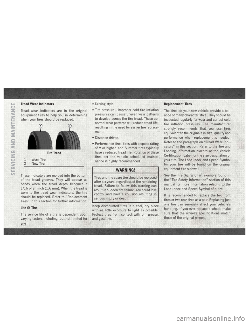
Tread Wear Indicators
Tread wear indicators are in the original
equipment tires to help you in determining
when your tires should be replaced.
These indicators are molded into the bottom
of the tread grooves. They will appear as
bands when the tread depth becomes a
1/16 of an inch (1.6 mm). When the tread is
worn to the tread wear indicators, the tire
should be replaced. Refer to “Replacement
Tires” in this section for further information.
Life Of Tire
The service life of a tire is dependent upon
varying factors including, but not limited to:• Driving style.
• Tire pressure - Improper cold tire inflation
pressures can cause uneven wear patterns
to develop across the tire tread. These ab-
normal wear patterns will reduce tread life,
resulting in the need for earlier tire replace-
ment.
• Distance driven.
• Performance tires, tires with a speed rating of V or higher, and Summer tires typically
have a reduced tread life. Rotation of these
tires per the vehicle scheduled mainte-
nance is highly recommended.
WARNING!
Tires and the spare tire should be replaced
after six years, regardless of the remaining
tread. Failure to follow this warning can
result in sudden tire failure. You could lose
control and have a collision resulting in
serious injury or death.
Keep dismounted tires in a cool, dry place
with as little exposure to light as possible.
Protect tires from contact with oil, grease,
and gasoline.
Replacement Tires
The tires on your new vehicle provide a bal-
ance of many characteristics. They should be
inspected regularly for wear and correct cold
tire inflation pressures. The manufacturer
strongly recommends that you use tires
equivalent to the originals in size, quality and
performance when replacement is needed.
Refer to the paragraph on “Tread Wear Indi-
cators” in this section. Refer to the Tire and
Loading Information placard or the Vehicle
Certification Label for the size designation of
your tire. The Load Index and Speed Symbol
for your tire will be found on the original
equipment tire sidewall.
See the Tire Sizing Chart example found in
the “Tire Safety Information” section of this
manual for more information relating to the
Load Index and Speed Symbol of a tire.
It is recommended to replace the two front
tires or two rear tires as a pair. Replacing just
one tire can seriously affect your vehicle’s
handling. If you ever replace a wheel, make
sure that the wheel’s specifications match
those of the original wheels.
Tire Tread
1 — Worn Tire
2 — New Tire
SERVICING AND MAINTENANCE
202
Page 206 of 298

Snow Tires
Some areas of the country require the use of
snow tires during the Winter. Snow tires can
be identified by a “mountain/snowflake”
symbol on the tire sidewall.If you need snow tires,
select tires equivalent
in size and type to the
original equipment
tires. Use snow tires
only in sets of four;
failure to do so may
adversely affect the
safety and handling of your vehicle.
Snow tires generally have lower speed ratings
than what was originally equipped with your
vehicle and should not be operated at sus-
tained speeds over 75 mph (120 km/h). For
speeds above 75 mph (120 km/h) refer to
original equipment or an authorized tire
dealer for recommended safe operating
speeds, loading and cold tire inflation pres-
sures. While studded tires improve performance on
ice, skid and traction capability on wet or dry
surfaces may be poorer than that of non-
studded tires. Some states prohibit studded
tires; therefore, local laws should be checked
before using these tire types.
Spare Tires — If Equipped
For vehicles equipped with Tire Service Kit
instead of a spare tire, please refer to “Tire
Service Kit” in “In Case Of Emergency” in
the Owner’s Manual at www.mopar.com/
en-us/care/owners-manual.html (U.S. Resi-
dents) or www.owners.mopar.ca (Canadian
Residents) for further information.
CAUTION!
Because of the reduced ground clearance,
do not take your vehicle through an auto-
matic car wash with a compact or limited
use temporary spare installed. Damage to
the vehicle may result.
Spare Tire Matching Original Equipped Tire
And Wheel — If Equipped
Your vehicle may be equipped with a spare
tire and wheel equivalent in look and func-
tion to the original equipment tire and wheel
found on the front or rear axle of your vehicle.
This spare tire may be used in the tire rota-
tion for your vehicle. If your vehicle has this
option, refer to an authorized tire dealer for
the recommended tire rotation pattern.
Compact Spare Tire — If Equipped
The compact spare is for temporary emer-
gency use only. You can identify if your ve-
hicle is equipped with a compact spare by
looking at the spare tire description on the
Tire and Loading Information Placard located
on the driver’s side door opening or on the
sidewall of the tire. Compact spare tire de-
scriptions begin with the letter “T” or “S”
preceding the size designation. Example:
T145/80D18 103M.
T,S=T
emporary Spare Tire
SERVICING AND MAINTENANCE
204