torque Ram 4500 Chassis Cab 2018 User Guide
[x] Cancel search | Manufacturer: RAM, Model Year: 2018, Model line: 4500 Chassis Cab, Model: Ram 4500 Chassis Cab 2018Pages: 298, PDF Size: 5.88 MB
Page 69 of 298
WARNING!
If you continue operating the vehicle when
the Transmission Temperature Warning
Light is illuminated you could cause the
fluid to boil over, come in contact with hot
engine or exhaust components and cause a
fire.
CAUTION!
Continuous driving with the Transmission
Temperature Warning Light illuminated
will eventually cause severe transmission
damage or transmission failure.
Yellow Indicator Lights
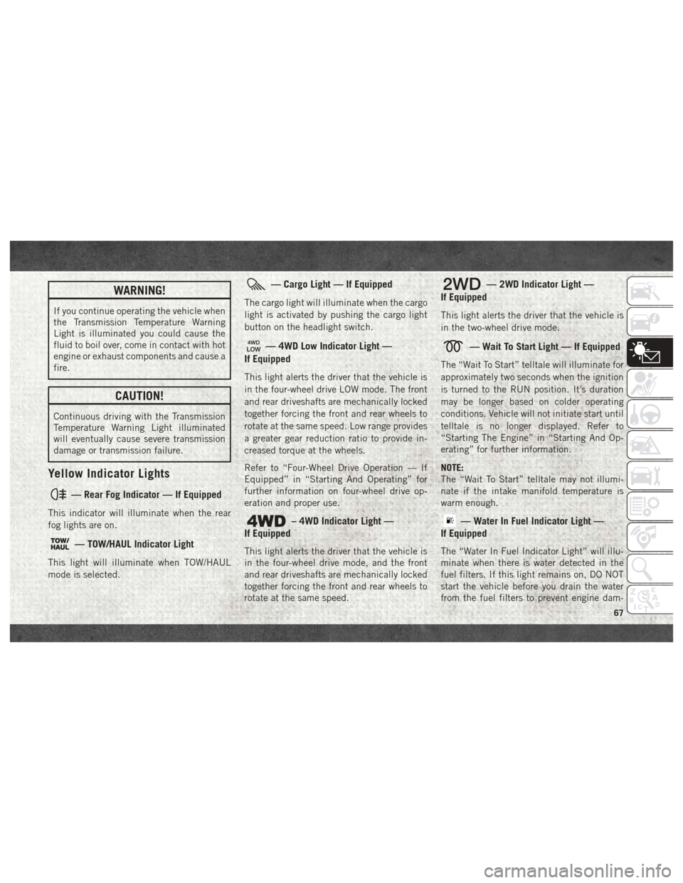
— Rear Fog Indicator — If Equipped
This indicator will illuminate when the rear
fog lights are on.
— TOW/HAUL Indicator Light
This light will illuminate when TOW/HAUL
mode is selected.
— Cargo Light — If Equipped
The cargo light will illuminate when the cargo
light is activated by pushing the cargo light
button on the headlight switch.
— 4WD Low Indicator Light —
If Equipped
This light alerts the driver that the vehicle is
in the four-wheel drive LOW mode. The front
and rear driveshafts are mechanically locked
together forcing the front and rear wheels to
rotate at the same speed. Low range provides
a greater gear reduction ratio to provide in-
creased torque at the wheels.
Refer to “Four-Wheel Drive Operation — If
Equipped” in “Starting And Operating” for
further information on four-wheel drive op-
eration and proper use.
– 4WD Indicator Light —
If Equipped
This light alerts the driver that the vehicle is
in the four-wheel drive mode, and the front
and rear driveshafts are mechanically locked
together forcing the front and rear wheels to
rotate at the same speed.
— 2WD Indicator Light —
If Equipped
This light alerts the driver that the vehicle is
in the two-wheel drive mode.
— Wait To Start Light — If Equipped
The “Wait To Start” telltale will illuminate for
approximately two seconds when the ignition
is turned to the RUN position. It’s duration
may be longer based on colder operating
conditions. Vehicle will not initiate start until
telltale is no longer displayed. Refer to
“Starting The Engine” in “Starting And Op-
erating” for further information.
NOTE:
The “Wait To Start” telltale may not illumi-
nate if the intake manifold temperature is
warm enough.
— Water In Fuel Indicator Light —
If Equipped
The “Water In Fuel Indicator Light” will illu-
minate when there is water detected in the
fuel filters. If this light remains on, DO NOT
start the vehicle before you drain the water
from the fuel filters to prevent engine dam-
67
Page 134 of 298

Electronically Shifted Transfer
Case (Four-Position Switch) —
If Equipped
The electronic shift transfer case is operated
by the 4WD Control Switch (Transfer Case
Switch), which is located on the instrument
panel.This electronically shifted transfer case pro-
vides four mode positions: • Two-Wheel Drive High Range (2WD)
• Four-Wheel Drive Lock High Range (4WD
LOCK)
• Four-Wheel Drive Low Range (4WD LOW)
• Neutral (NEUTRAL)
For additional information on the appropriate
use of each transfer case mode position, see
the information below:
2WD
Rear Wheel Drive High Range — This range is
for normal street and highway driving on dry,
hard surfaced roads.
4WD LOCK
Four-Wheel Drive Lock High Range — This
range maximizes torque to the front drive-
shaft, forcing the front and rear wheels to
rotate at the same speed. This range provides
additional traction for loose, slippery road
surfaces only.
4WD LOW
Four-Wheel Drive Low Range — This range
provides low speed four-wheel drive. It maxi-
mizes torque to the front driveshaft, forcing
Four-Position/Part Time Transfer Case
STARTING AND OPERATING
132
Page 135 of 298

the front and rear wheels to rotate at the same
speed. This range provides additional trac-
tion and maximum pulling power for loose,
slippery road surfaces only. Do not exceed
25 mph (40 km/h).
NEUTRAL (N)
Neutral — This range disengages both the
front and rear driveshafts from the pow-
ertrain. To be used for flat towing behind
another vehicle. Refer to “Recreational Tow-
ing” in this section for further information.
WARNING!
You or others could be injured or killed if
you leave the vehicle unattended with the
transfer case in the NEUTRAL position
without first fully engaging the parking
brake. The transfer case NEUTRAL posi-
tion disengages both the front and rear
drive shafts from the powertrain and will
allow the vehicle to roll, even if the trans-
mission is in PARK. The parking brake
should always be applied when the driver
is not in the vehicle.This electronically shifted transfer case is
designed to be driven in the two-wheel drive
position (2WD) for normal street and highway
conditions on dry, hard surfaced roads.
When additional traction is required, the
transfer case 4WD LOCK and 4WD LOW po-
sitions can be used to maximize torque to the
front driveshaft, forcing the front and rear
wheels to rotate at the same speed. This is
accomplished by rotating the 4WD Control
Switch to the desired position.
Refer to “Shifting Procedure” in the “Start-
ing And Operating” section of your Owner’s
Manual
locatedat
www.mopar.com/en-us/care/owners-manual.html
(U.S. Residents) or www.owners.mopar.ca
(Canadian Residents) for specific shifting in-
structions.
SPEED CONTROL
When engaged, the Speed Control takes over
accelerator operations at speeds greater than
25 mph (40 km/h). The Speed Control buttons are located on the
right side of the steering wheel.
Speed Control Buttons
1 — Push Cancel
2 — Push On/Off
3 — Push Resume/Accel
4 — Push Set/Decel
133
Page 165 of 298
4. By rotating the lug wrench clockwise,raise the vehicle until the wheel just
clears the surface.
WARNING!
Raising the vehicle higher than necessary
can make the vehicle less stable. It could
slip off the jack and hurt someone near it.
Raise the vehicle only enough to remove
the tire.
5. Remove the lug nuts and pull the wheel off. Install the spare wheel and lug nuts
with the cone shaped end of the nuts
toward the wheel on single rear wheel
(SRW) models. On dual rear wheel models
(DRW) the lug nuts are a two-piece assem-
bly with a flat face. Lightly tighten the
nuts. To avoid risk of forcing the vehicle
off the jack, do not fully tighten the nuts
until the vehicle has been lowered.
6. Using the lug wrench, finish tightening the nuts using a crisscross pattern. For
the proper lug nut torque specifications
refer to “Wheel And Tire Torque Specifi-
cations” in “Technical Specifications.” If
in doubt about the correct tightness, have them checked with a torque wrench by an
authorized dealer or at a service station.
WARNING!
A loose tire or jack thrown forward in a
collision or hard stop, could endanger the
occupants of the vehicle. Always stow the
jack parts and the spare tire in the places
provided.
7. Install wheel center cap (if equipped) and remove wheel blocks. Do not install
chrome or aluminum wheel center caps
on the spare wheel. This may result in cap
damage.
8. Lower the jack to its fully closed position. If the jack will not lower by turning the
dial (thumbwheel) by hand, it may be
necessary to use the jack driver in order to
lower the jack. Stow the replaced tire,
jack, and tools as previously described.
9. Adjust the tire pressure when possible.
To Stow The Flat Or Spare —
If Equipped
Refer to Upfitters Body Builders Guide for
information on stowing your spare tire (if
equipped).
Hub Caps/Wheel Covers —
If Equipped
The hub caps must be removed before raising
the vehicle off the ground.
CAUTION!
Use extreme caution when removing the
front and rear center caps. Damage can
occur to the center cap and/or the wheel if
screwdriver type tools are used. A pulling
motion, not a pry off motion, is recom-
mended to remove the caps.
For single rear wheel (SRW) models, use the
flat blade on the end of the lug wrench to pull
the hub cap off. Insert the blade end into the
pull off notch and carefully pull the hub cap
off with a back and forth motion.
163
Page 211 of 298

TECHNICAL SPECIFICATIONS
WHEEL AND TIRE TORQUE
SPECIFICATIONS..............210
Torque Specifications ...........210
Dual Rear Wheels ..............211
FLUID CAPACITIES — GAS ENGINE . . .213 FLUID CAPACITIES — 6.7L CUMMINS
DIESEL ENGINE
...............213
FLUIDS AND LUBRICANTS —
GAS ENGINE ................ .214Engine.....................214
Chassis ....................216
FLUIDS AND LUBRICANTS —
6.7L DIESEL ENGINES ...........216
Engine.....................216
Chassis ....................218
MOPAR ACCESSORIES ...........219
Authentic Accessories By Mopar .....219
TECHNICAL SPECIFICATIONS
209
Page 212 of 298
WHEEL AND TIRE TORQUE
SPECIFICATIONS
Proper lug nut/bolt torque is very important to
ensure that the wheel is properly mounted to
the vehicle. Any time a wheel has been re-
moved and reinstalled on the vehicle, the lug
nuts/bolts should be torqued using a properly
calibrated torque wrench using a high quality
six sided (hex) deep wall socket.
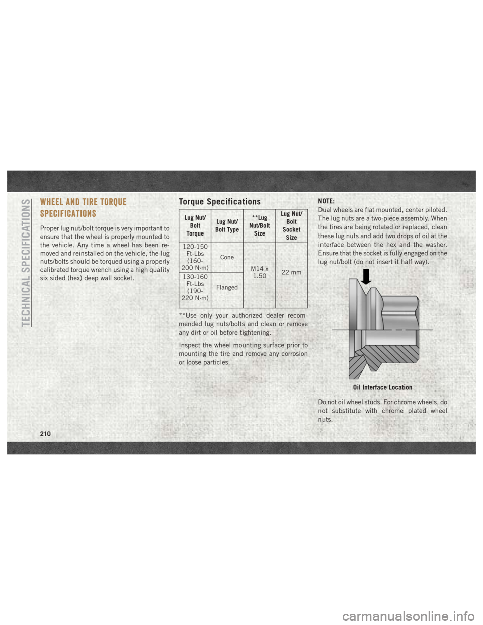
Torque Specifications
Lug Nut/Bolt
Torque Lug Nut/
Bolt Type **Lug
Nut/Bolt Size Lug Nut/
Bolt
Socket Size
120-150 Ft-Lbs(160-
200 N·m) Cone
M14 x1.50 22 mm
130-160
Ft-Lbs(190-
220 N·m) Flanged
**Use only your authorized dealer recom-
mended lug nuts/bolts and clean or remove
any dirt or oil before tightening.
Inspect the wheel mounting surface prior to
mounting the tire and remove any corrosion
or loose particles. NOTE:
Dual wheels are flat mounted, center piloted.
The lug nuts are a two-piece assembly. When
the tires are being rotated or replaced, clean
these lug nuts and add two drops of oil at the
interface between the hex and the washer.
Ensure that the socket is fully engaged on the
lug nut/bolt (do not insert it half way).
Do not oil wheel studs. For chrome wheels, do
not substitute with chrome plated wheel
nuts.
Oil Interface Location
TECHNICAL SPECIFICATIONS
210
Page 213 of 298
Retighten the wheel nuts in the same se-
quence to the torques listed in the table. Go
through the sequence a second time to verify
that specific torque has been achieved. Re-
tighten to specifications after 25 miles
(40 km) and check the lug nut/bolt torque to
be sure that all the lug nuts/bolts are properly
seated against the wheel.
It is recommended that wheel stud nuts be
kept torqued to specifications at all times.
Torque wheel stud nuts to specifications at
each lubrication interval.
All wheel nuts should be tightened occasion-
ally to eliminate the possibility of wheel studs
being sheared or the bolt holes in the wheels
becoming elongated. This is especially im-
portant during the first few hundred miles/
kilometers of operation to allow the wheel
nuts to become properly set. All wheel nuts
should first be firmly seated against the
wheel. The wheel nuts should then be tight-
ened to recommended torque. Tighten the
wheel nuts to final torque in increments.Progress around the bolt circle, tightening
the wheel nut opposite to the wheel nut just
previously tightened until final torque is
achieved.
WARNING!
To avoid the risk of forcing the vehicle off
the jack, do not tighten the lug nuts fully
until the vehicle has been lowered. Failure
to follow this warning may result in per-
sonal injury.
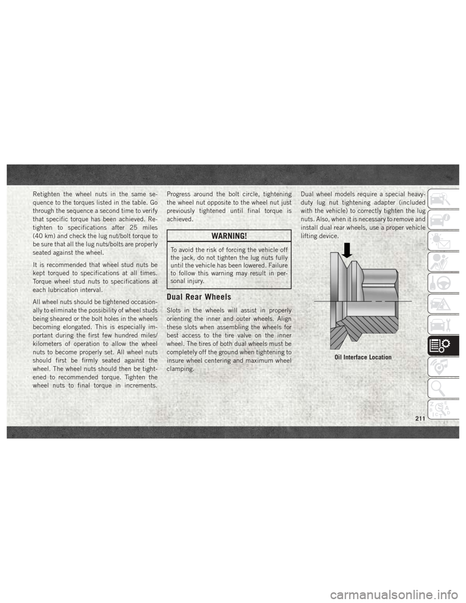
Dual Rear Wheels
Slots in the wheels will assist in properly
orienting the inner and outer wheels. Align
these slots when assembling the wheels for
best access to the tire valve on the inner
wheel. The tires of both dual wheels must be
completely off the ground when tightening to
insure wheel centering and maximum wheel
clamping.
Dual wheel models require a special heavy-
duty lug nut tightening adapter (included
with the vehicle) to correctly tighten the lug
nuts. Also, when it is necessary to remove and
install dual rear wheels, use a proper vehicle
lifting device.
Oil Interface Location
211
Page 214 of 298

NOTE:
When installing a spare tire (if equipped) as
part of a dual rear wheel end combination,
the tire diameter of the two individual tires
must be compared. If there is a significant
difference, the larger tire should be installed
in a front location. The correct direction of
rotation for dual tire installations must also
be observed.
These dual rear wheels should be tightened as
follows:It is recommended that wheel stud nuts be
kept torqued to specifications at all times.
Torque wheel stud nuts to specifications at
each lubrication interval.
Wheel Nuts Numbered Sequence (8)
Wheel Nuts Numbered Sequence (10)TECHNICAL SPECIFICATIONS
212
Page 296 of 298
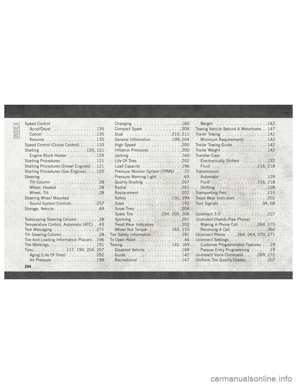
Speed ControlAccel/Decel ...............135
Cancel ..................135
Resume .................135
Speed Control (Cruise Control) ......133
Starting ................120, 121
Engine Block Heater ..........124
Starting Procedures .............121
Starting Procedures (Diesel Engines) . .121
Starting Procedures (Gas Engines) . . . .120
Steering Tilt Column ................28
Wheel, Heated ..............28
Wheel, Tilt .................28
Steering Wheel Mounted Sound System Controls .........257
Storage, Vehicle ................44
Telescoping Steering Column ........28
Temperature Control, Automatic (ATC) . .43
Text Messaging ...............271
Tilt Steering Column .............28
Tire And Loading Information Placard . .196
Tire Markings .................191
Tires ............117, 199, 204, 207
Aging (Life Of Tires) ..........202
Air Pressure ...............199 Changing
.................160
Compact Spare .............204
Dual ................210, 211
General Information .......199, 204
High Speed ...............200
Inflation Pressures ...........200
Jacking ..................160
Life Of Tires ...............202
Load Capacity ..............196
Pressure Monitor System (TPMS) . . .72
Pressure Warning Light .........65
Quality Grading .............207
Radial ..................201
Replacement ..............202
Safety ...............191, 199
Sizes ...................192
Snow Tires ................204
Spare
Tire .........204, 205, 206
Spinning .................201
Tread Wear Indicators .........202
Wheel Nut Torque ........163, 210
Tire Safety Information ...........191
To Open Hood .................44
Towing .................142, 169
Disabled Vehicle ............169
Guide ...................142
Recreational ...............147 Weight
..................142
Towing Vehicle Behind A Motorhome . .147
Trailer Towing ................142
Minimum Requirements .......142
Trailer Towing Guide ............142
Trailer Weight ................142
Transfer Case Electronically Shifted .........132
Fluid ................216, 218
Transmission Automatic ................129
Fluid ................216, 218
Shifting .................128
Transporting Pets ..............115
Tread Wear Indicators ...........202
Turn Signals ...............34, 68
Uconnect 3.0 ................227
Uconnect (Hands-Free Phone) Making A Phone Call ......264, 270
Receiving A Call ............264
Uconnect Phone . . . .264, 269, 270, 271
Uconnect Settings Customer Programmable Features . . .19
Passive Entry Programming .......19
Uconnect Voice Command .....269, 272
Uniform Tire Quality Grades ........207
INDEX
294
Page 297 of 298
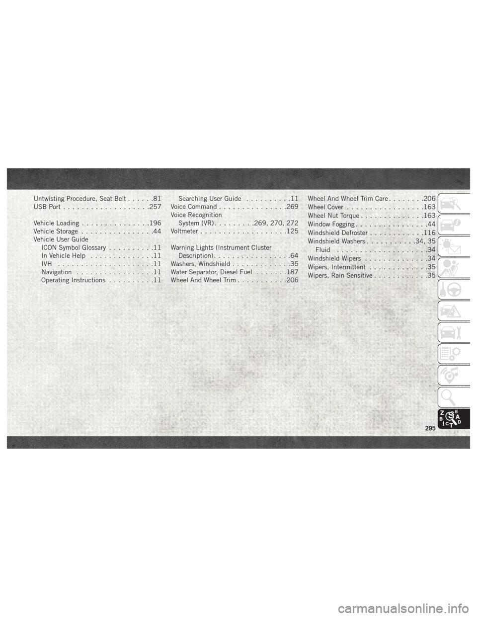
Untwisting Procedure, Seat Belt......81
USB Port ...................257
Vehicle Loading ...............196
Vehicle Storage ................44
Vehicle User Guide ICON Symbol Glossary ..........11
In Vehicle Help ..............11
IVH .....................11
Navigation .................11
Operating Instructions ..........11 Searching User Guide
..........11
Voice Command ...............269
Voice Recognition System (VR) .........269, 270, 272
Voltmeter ...................125
Warning Lights (Instrument Cluster Description) .................64
Washers, Windshield .............35
Water Separator, Diesel Fuel .......187
Wheel And Wheel Trim ...........206 Wheel And Wheel Trim Care
........206
Wheel Cover .................163
Wheel Nut Torque ..............163
Window Fogging ................44
Windshield Defroster ............116
Windshield Washers ...........34, 35
Fluid ....................34
Windshield Wipers ..............34
Wipers, Intermittent .............35
Wipers, Rain Sensitive ............35
295