window Ram 4500 Chassis Cab 2018 User Guide
[x] Cancel search | Manufacturer: RAM, Model Year: 2018, Model line: 4500 Chassis Cab, Model: Ram 4500 Chassis Cab 2018Pages: 298, PDF Size: 5.88 MB
Page 9 of 298
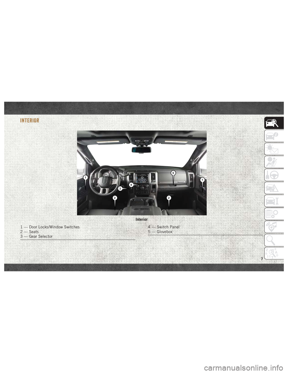
INTERIOR
Interior
1 — Door Locks/Window Switches
2 — Seats
3 — Gear Selector4 — Switch Panel
5 — Glovebox
7
Page 19 of 298
• If an engine fault is present or fuel level islow, the vehicle will start and then shut
down in 10 seconds.
• The park lamps will turn on and remain on during Remote Start mode.
• For security, power window and power sun- roof operation (if equipped) are disabled
when the vehicle is in the Remote Start
mode.
• The engine can be started two consecutive times (two 15-minute cycles) with the key
fob. However, the ignition must be placed
in the ON/RUN position before you can
repeat the start sequence for a third cycle.
To Exit Remote Start Mode
Without Driving The Vehicle
Push and release the remote start button one
time or allow the engine to run for the entire
15-minute cycle.
NOTE:
To avoid unintentional shutdowns, the system
will disable with a one time push of the
remote start button for two seconds after
receiving a valid remote start request.
To Exit Remote Start Mode And
Drive The Vehicle
Before the end of the 15-minute cycle, push
and release the unlock button on the key fob
to unlock the doors and disarm the vehicle
security alarm system (if equipped). Then,
prior to the end of the 15-minute cycle, cycle
the ignition to the ON/RUN position.
General Information
The following regulatory statement applies to
all radio frequency (RF) devices equipped in
this vehicle:
This device complies with Part 15 of the FCC
Rules and with Industry Canada license-
exempt RSS standard(s). Operation is sub-
ject to the following two conditions:
1. This device may not cause harmful inter-
ference, and
2. This device must accept any interference received, including interference that may
cause undesired operation. NOTE:
Changes or modifications not expressly ap-
proved by the party responsible for compli-
ance could void the user’s authority to oper-
ate the equipment.
VEHICLE SECURITY ALARM
The vehicle security alarm monitors the ve-
hicle doors and ignition for unauthorized op-
eration. When the vehicle security alarm is
activated, interior switches for door locks are
disabled. The system provides both audible
and visible signals for the first three minutes.
The horn will sound, the headlights will turn
on, the park lamps and/or turn signals will
flash and vehicle security light will flash
repeatedly. For an additional 15 minutes
only, the headlights will turn on, the park
lamps and/or turn signals, and vehicle secu-
rity light will flash.
17
Page 41 of 298

Control Descriptions
NOTE:
Icons and descriptions can vary based upon vehicle equipment.
IconDescription
MAX A/C Button
Press and release to change the current setting, the indicator illuminates when MAX A/C is on. Performing this function
again will cause the MAX A/C operation to switch into manual mode and the MAX A/C indicator will turn off.
A/C Button
Press and release the button on the touchscreen, or push and release the button on the faceplate, to change the current
setting, the indicator illuminates when A/C is on.
Recirculation Button
Press and release this button to change the system between recirculation mode and outside air mode.
Recirculation can be used when outside conditions such as smoke, odors, dust, or high humidity are present.
NOTE:
• Continuous use of the Recirculation mode may make the inside air stuffy and window fogging may occur.
Extended use of this mode is not recommended.
• The use of the Recirculation mode in cold or damp weather could cause windows to fog on the inside, because
of moisture buildup inside the vehicle. Select the outside air position for maximum defogging.
• Recirculation can be used in all modes except for Defrost.
• The A/C can be deselected manually without disturbing the mode control selection.
AUTO Button — If Equipped
Automatically controls the interior cabin temperature by adjusting airflow distribution and amount.
Toggling this function will cause the system to switch between manual mode and automatic modes.
Refer to “Automatic Operation” for more information.
39
Page 42 of 298

IconDescription
Front Defrost Button
Press and release the touchscreen button, or push and release the button on the faceplate, to change the current
airflow setting to Defrost mode. The indicator illuminates when this feature is on. Air comes from the windshield and
side window demist outlets. When the defrost button is selected, the blower level may increase. Use Defrost mode with
maximum temperature settings for best windshield and side window defrosting and defogging. When toggling the front
defrost mode button, the climate system will return to previous setting.
Rear Defrost Button
Push and release the button on the touchscreen, or push and release the button on the faceplate, to turn on the rear
window defroster and the heated outside mirrors (if equipped). An indicator will illuminate when the rear window
defroster is on. The rear window defroster automatically turns off after ten minutes.
Uconnect 3
Uconnect 4C/4C NAV
Driver and Passenger Temperature Up and Down Buttons
Provides the driver and passenger with independent temperature control. Push the up arrow button on the faceplate,
press the up arrow button on the touchscreen, or press and slide the temperature bar towards the red arrow button on
the touchscreen for warmer temperature settings. Push the down arrow button on the faceplate, press the down arrow
button on the touchscreen, or press and slide the temperature bar towards the blue arrow button on the touchscreen for
cooler temperature settings. When the SYNC feature is active, the passenger’s temperature will move up and down with
the driver’s temperature, when it is increased and decreased, respectively.
NOTE:
Temperature numbers will only be displayed if the system is equipped with Automatic Temperature Control.
GETTING TO KNOW YOUR VEHICLE
40
Page 43 of 298
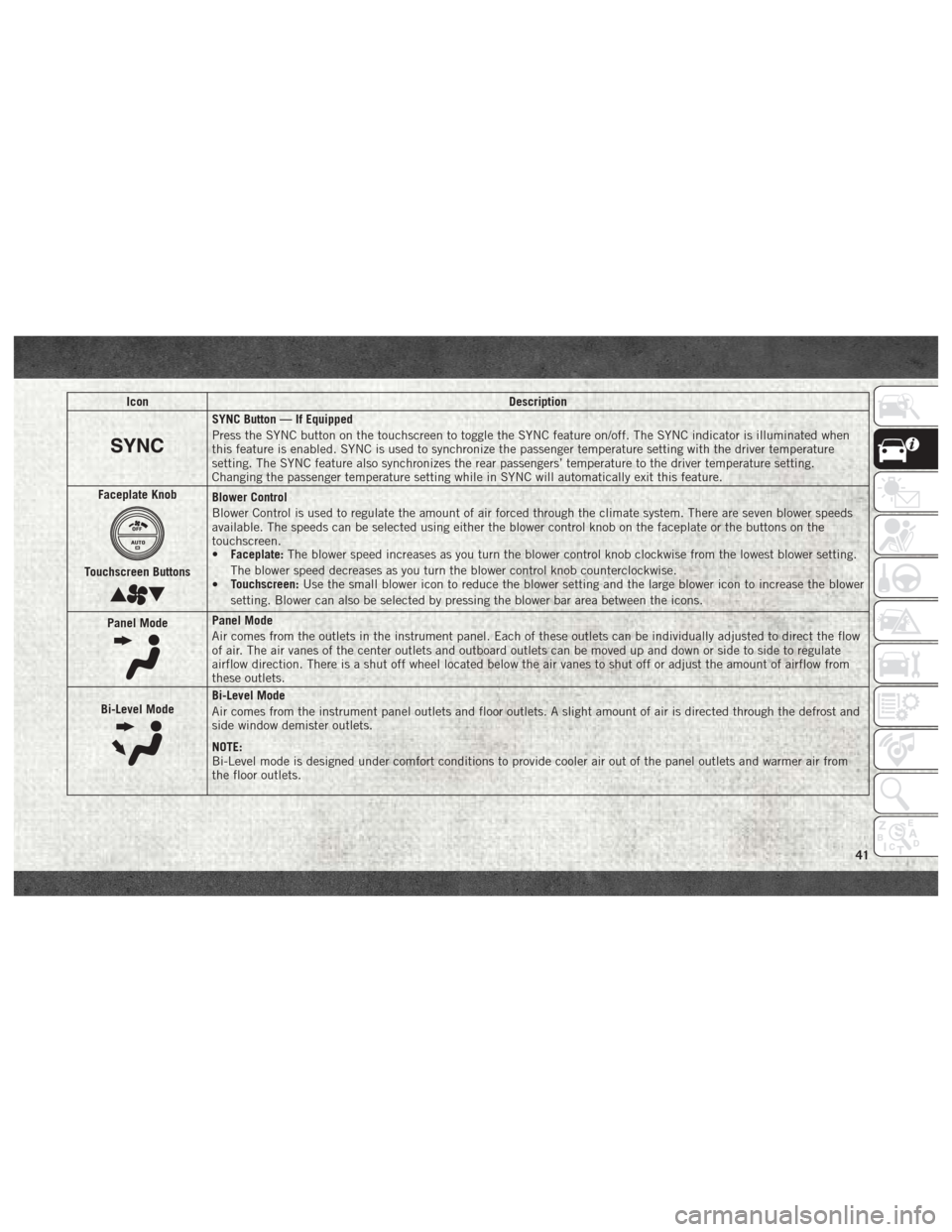
IconDescription
SYNC Button — If Equipped
Press the SYNC button on the touchscreen to toggle the SYNC feature on/off. The SYNC indicator is illuminated when
this feature is enabled. SYNC is used to synchronize the passenger temperature setting with the driver temperature
setting. The SYNC feature also synchronizes the rear passengers’ temperature to the driver temperature setting.
Changing the passenger temperature setting while in SYNC will automatically exit this feature.
Faceplate Knob
Touchscreen Buttons
Blower Control
Blower Control is used to regulate the amount of air forced through the climate system. There are seven blower speeds
available. The speeds can be selected using either the blower control knob on the faceplate or the buttons on the
touchscreen.
• Faceplate: The blower speed increases as you turn the blower control knob clockwise from the lowest blower setting.
The blower speed decreases as you turn the blower control knob counterclockwise.
• Touchscreen:
Use the small blower icon to reduce the blower setting and the large blower icon to increase the blower
setting. Blower can also be selected by pressing the blower bar area between the icons.
Panel Mode
Panel Mode
Air comes from the outlets in the instrument panel. Each of these outlets can be individually adjusted to direct the flow
of air. The air vanes of the center outlets and outboard outlets can be moved up and down or side to side to regulate
airflow direction. There is a shut off wheel located below the air vanes to shut off or adjust the amount of airflow from
these outlets.
Bi-Level Mode
Bi-Level Mode
Air comes from the instrument panel outlets and floor outlets. A slight amount of air is directed through the defrost and
side window demister outlets.
NOTE:
Bi-Level mode is designed under comfort conditions to provide cooler air out of the panel outlets and warmer air from
the floor outlets.
41
Page 44 of 298
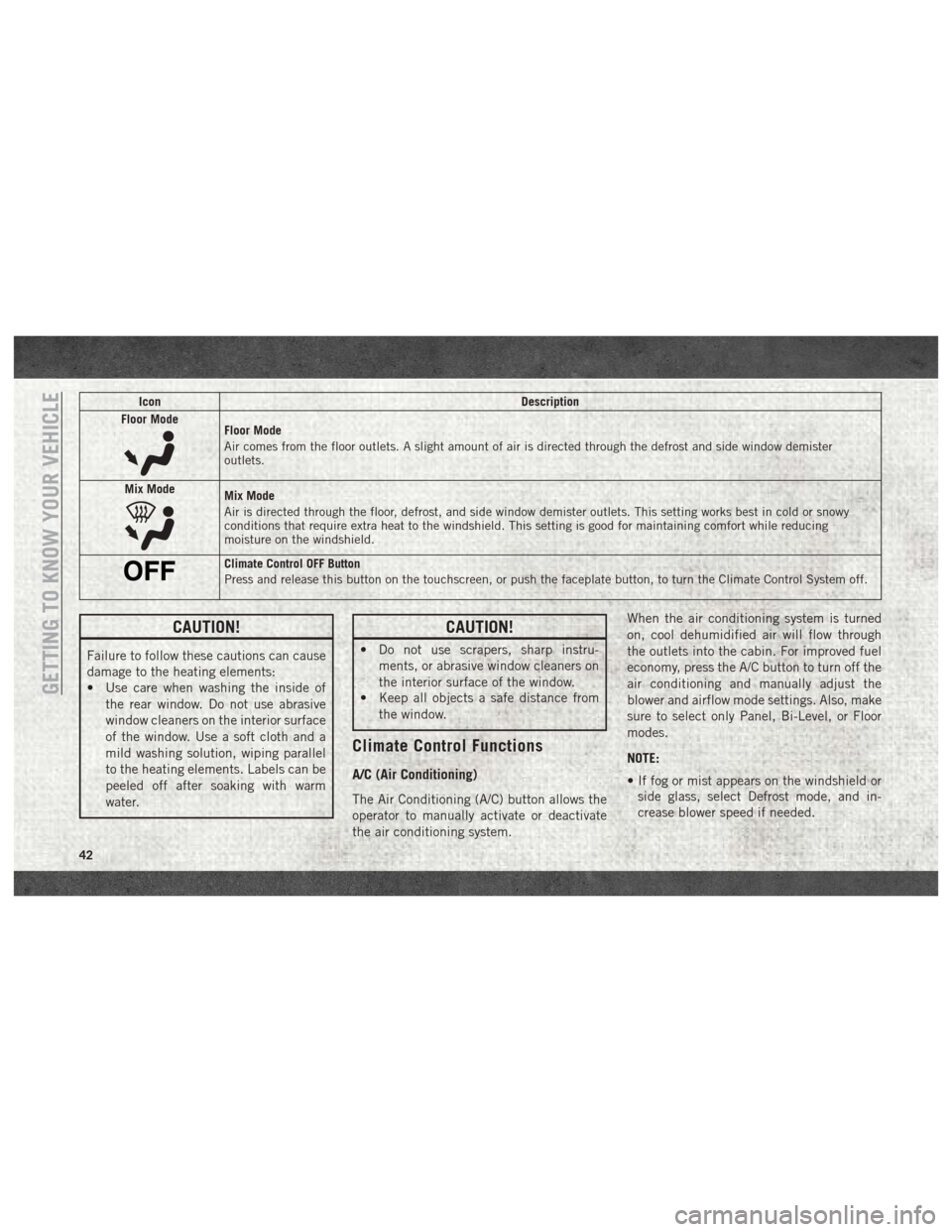
IconDescription
Floor Mode
Floor Mode
Air comes from the floor outlets. A slight amount of air is directed through the defrost and side window demister
outlets.
Mix Mode
Mix Mode
Air is directed through the floor, defrost, and side window demister outlets. This setting works best in cold or snowy
conditions that require extra heat to the windshield. This setting is good for maintaining comfort while reducing
moisture on the windshield.
Climate Control OFF Button
Press and release this button on the touchscreen, or push the faceplate button, to turn the Climate Control System off.
CAUTION!
Failure to follow these cautions can cause
damage to the heating elements:
• Use care when washing the inside of the rear window. Do not use abrasive
window cleaners on the interior surface
of the window. Use a soft cloth and a
mild washing solution, wiping parallel
to the heating elements. Labels can be
peeled off after soaking with warm
water.
CAUTION!
• Do not use scrapers, sharp instru-ments, or abrasive window cleaners on
the interior surface of the window.
• Keep all objects a safe distance from
the window.
Climate Control Functions
A/C (Air Conditioning)
The Air Conditioning (A/C) button allows the
operator to manually activate or deactivate
the air conditioning system. When the air conditioning system is turned
on, cool dehumidified air will flow through
the outlets into the cabin. For improved fuel
economy, press the A/C button to turn off the
air conditioning and manually adjust the
blower and airflow mode settings. Also, make
sure to select only Panel, Bi-Level, or Floor
modes.
NOTE:
• If fog or mist appears on the windshield or
side glass, select Defrost mode, and in-
crease blower speed if needed.
GETTING TO KNOW YOUR VEHICLE
42
Page 45 of 298
• If your air conditioning performance seemslower than expected, check the front of the
A/C condenser (located in front of the ra-
diator), for an accumulation of dirt or in-
sects. Clean with a gentle water spray from
the front of the radiator and through the
condenser.
MAX A/C
MAX A/C sets the control for maximum cool-
ing performance.
Press and release to toggle between MAX A/C
and the prior settings. The button illuminates
when MAX A/C is on.
In MAX A/C, the blower level and mode posi-
tion can be adjusted to desired user settings.
Pressing other settings will cause the MAX
A/C operation to switch to the selected set-
ting and MAX A/C to exit.
Recirculation
When outside air contains smoke, odors, or
high humidity, or if rapid cooling is desired,
you may wish to recirculate interior air by
pressing the Recirculation control button.
The Recirculation indicator will illuminate when this button is selected. Press the button
a second time to turn off the Recirculation
mode and allow outside air into the vehicle.
NOTE:
In cold weather, use of Recirculation mode
may lead to excessive window fogging. The
Recirculation feature may be unavailable
(button on the touchscreen greyed out) if
conditions exist that could create fogging on
the inside of the windshield.
Automatic Temperature Control
(ATC) — If Equipped
Automatic Operation
1. Push the AUTO button on the faceplate,
or the AUTO button on the touchscreen on
the Automatic Temperature Control (ATC)
Panel.
2. Next, adjust the temperature you would like the system to maintain by adjusting
the driver and passenger temperature
control buttons. Once the desired tem-
perature is displayed, the system will
achieve and automatically maintain that
comfort level. 3. When the system is set up for your comfort
level, it is not necessary to change the
settings. You will experience the greatest
efficiency by simply allowing the system
to function automatically.
NOTE:
• It is not necessary to move the temperature settings for cold or hot vehicles. The system
automatically adjusts the temperature,
mode, and blower speed to provide comfort
as quickly as possible.
• The temperature can be displayed in U.S. or Metric units by selecting the US/Metric
customer-programmable feature. Refer to
the “Uconnect Settings” in “Multimedia”
in your Owner’s Manual at www.mopar.com/
en-us/care/owners-manual.html (U.S.
Residents) or www.owners.mopar.ca
(Canadian Residents) for further information.
To provide you with maximum comfort in the
Automatic mode during cold start-ups, the
blower fan will remain on low until the engine
warms up. The blower will increase in speed
and transition into Auto mode.
43
Page 46 of 298
Manual Operation Override
This system offers a full complement of
manual override features. The AUTO symbol
in the front ATC display will be turned off
when the system is being used in the manual
mode.
Operating Tips
Summer Operation
The engine cooling system must be protected
with a high-quality antifreeze coolant to pro-
vide proper corrosion protection and to pro-
tect against engine overheating. OAT coolant
(conforming to MS.90032) is recommended.
Winter Operation
To ensure the best possible heater and de-
froster performance, make sure the engine
cooling system is functioning properly and
the proper amount, type, and concentration
of coolant is used. Use of the Air Recircula-
tion mode during Winter months is not rec-
ommended, because it may cause window
fogging.
Vacation/Storage
Before you store your vehicle, or keep it out of
service (i.e., vacation) for two weeks or more,
run the air conditioning system at idle for
about five minutes, in fresh air with the
blower setting on high. This will ensure ad-
equate system lubrication to minimize the
possibility of compressor damage when the
system is started again.
Window Fogging
Vehicle windows tend to fog on the inside in
mild, rainy, and/or humid weather. To clear
the windows, select Defrost or Mix mode and
increase the front blower speed. Do not use
the Recirculation mode without A/C for long
periods, as fogging may occur.
Outside Air Intake
Make sure the air intake, located directly in
front of the windshield, is free of obstruc-
tions, such as leaves. Leaves collected in the
air intake may reduce airflow, and if they
enter the plenum, they could plug the water
drains. In Winter months, make sure the air
intake is clear of ice, slush, and snow.
Cabin Air Filter
The climate control system filters out dust
and pollen from the air. Contact an autho-
rized dealer to service your cabin air filter,
and to have it replaced when needed.
HOOD
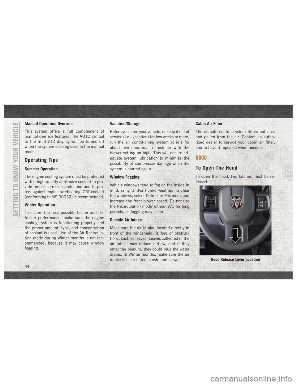
To Open The Hood
To open the hood, two latches must be re-
leased.
Hood Release Lever Location
GETTING TO KNOW YOUR VEHICLE
44
Page 77 of 298
• Signal interference due to electronic de-vices or driving next to facilities emitting
the same radio frequencies as the TPM
sensors.
• Installing aftermarket window tinting that contains materials that may block radio
wave signals.
• Accumulation of snow or ice around the wheels or wheel housings.
• Using tire chains on the vehicle.
• Using wheels/tires not equipped with TPM sensors.
A system fault may occur due to an incorrect
TPM sensor location condition. When a sys-
tem fault occurs due to an incorrect TPM
sensor location, the “Tire Pressure Monitor-
ing Telltale Light” will flash on and off for
75 seconds and then remain on solid. The
system fault will also sound a chime. In
addition, the instrument cluster will display a
“Tire Pressure Temporarily Unavailable”
message in place of the tire pressure display
screen. If the ignition switch is cycled, this
sequence will repeat, providing the system
fault still exists. If the system fault no longer
exists, the “Tire Pressure Monitoring Telltale Light” will no longer flash and the tire pres-
sure display screen will be displayed showing
the tire pressure values the correct locations.
Vehicles With Non Matching Full Size Spare Or
Compact Spare
• The non matching full size spare or com-
pact spare tire does not have a TPM sensor.
Therefore, the TPMS will not monitor the
pressure in the non matching full size spare
or compact spare tire.
• If you install the non matching full size spare or compact spare tire in place of a
road tire that has a pressure below the
low-pressure warning limit, upon the next
ignition switch cycle, the TPM Telltale
Light and a “LOW TIRE” message will re-
main ON and a chime will sound. In addi-
tion, the graphic in the instrument cluster
will still display a pressure value in a differ-
ent color.
• After driving the vehicle for up to 20 min- utes above 15 mph (24 km/h), the TPM
Telltale Light will flash on and off for
75 seconds and then remain on solid. In
addition, the instrument cluster will display a "SERVICE TPM SYSTEM" message for a
minimum of five seconds and then display
dashes (- -) in place of the pressure value.
• For each subsequent ignition switch cycle, a chime will sound, the TPM Telltale Light
will flash on and off for 75 seconds and
then remain on solid, and the instrument
cluster will display a "SERVICE TPM SYS-
TEM" message for a minimum of five sec-
onds and then display dashes (- -) in place
of the pressure value.
• Once you repair or replace the original road tire and reinstall it on the vehicle in place of
the non matching full size spare or compact
spare, the TPMS will update automatically.
In addition, the TPM Telltale Light will turn
OFF and the graphic in the instrument
cluster will display a new pressure value
instead of dashes (- -), as long as no tire
pressure is below the low-pressure warning
limit in any of the four active road tires. The
vehicle may need to be driven for up to
20 minutes above 15 mph (24 km/h) in
order for the TPMS to receive this
information.
75
Page 78 of 298

Tire Pressure Information System (TPIS)
Chassis Cab — If Equipped
Your vehicle may be equipped with a Tire
Pressure Information System (TPIS).
The Tire Pressure Information System (TPIS)
uses wireless technology with wheel rim
mounted electronic sensors to transmit tire
pressure levels. Sensors mounted to each
wheel as part of the valve stem transmit tire
pressure readings to the receiver module.
NOTE:
It is particularly important for you to check
the tire pressure in all of the tires on your
vehicle monthly and to maintain the proper
pressure.
The TPIS consists of the following compo-
nents:
• Receiver module
• Four TPM sensors (Single Rear Wheel[SRW] applications)
• Six TPM sensors (Dual Rear Wheel [DRW] applications)
• Pressure display in the instrument cluster display. The TPIS system will display all four (Single
Rear Wheel [SRW] applications) or six (Dual
Rear Wheel [DRW] applications) tire pressure
values in the instrument cluster display.
If a system fault is detected, the instrument
cluster will display a "SERVICE TPM SYS-
TEM" message for a minimum of five seconds
and then display dashes (- -) in place of the
pressure value to indicate which sensor is not
being received.
If the ignition switch is cycled, this sequence
will repeat, providing the system fault still
exists. If the system fault no longer exists, the
"SERVICE TPM SYSTEM" message will no
longer be displayed, and a pressure value will
display in place of the dashes. A system fault
can occur due to any of the following:
• Signal interference due to electronic de-
vices or driving next to facilities emitting
the same radio frequencies as the TPM
sensors.
• Installing aftermarket window tinting that contains materials that may block radio
wave signals.
• Accumulation of snow or ice around the wheels or wheel housings. • Using tire chains on the vehicle.
• Using wheels/tires not equipped with TPM
sensors.
General Information
This device complies with Part 15 of the FCC
rules and RSS 210 of Industry Canada. Op-
eration is subject to the following conditions:
1. This device may not cause harmful
interference.
2. This device must accept any interference received, including interference that may
cause undesired operation.
NOTE:
Changes or modifications not expressly ap-
proved by the party responsible for compli-
ance could void the user’s authority to oper-
ate the equipment.
OCCUPANT RESTRAINT SYSTEMS
Some of the most important safety features in
your vehicle are the restraint systems:
SAFETY
76