warning Ram 4500 Chassis Cab 2019 Owner's Guide
[x] Cancel search | Manufacturer: RAM, Model Year: 2019, Model line: 4500 Chassis Cab, Model: Ram 4500 Chassis Cab 2019Pages: 607, PDF Size: 10.72 MB
Page 49 of 607

GETTING TO KNOW YOUR VEHICLE 47
• When you remove the key fob from the ignition, thedriver’s seat will move to a position 0.3 inches (7.7 mm)
forward of the rear stop if the driver’s seat position is
between 0.9 inches and 2.7 inches (22.7 mm and 67.7 mm)
forward of the rear stop. The seat will return to its previ -
ously set position when you place the ignition to the ACC
or RUN position.
• The Easy Entry/Easy Exit feature is disabled when the driver’s seat position is less than 0.9 inches (22.7 mm)
forward of the rear stop. At this position, there is no benefit
to the driver by moving the seat for Easy Exit or Easy
Entry.
Each stored memory setting will have an associated Easy
Entry and Easy Exit position.
NOTE:
The Easy Entry/Exit feature is not enabled when the vehicle
is delivered from the factory. The Easy Entry/Exit feature is
enabled (or later disabled) through the programmable
features in the Uconnect system. Refer to “Uconnect
Settings” in “Multimedia” for further information.Heated Seats — If Equipped
On some models, the front and rear seats may be equipped
with heaters located in the seat cushions and seat backs.
WARNING!
• Persons who are unable to feel pain to the skin because of advanced age, chronic illness, diabetes, spinal cord
injury, medication, alcohol use, exhaustion or other
physical condition must exercise care when using the
seat heater. It may cause burns even at low tempera -
tures, especially if used for long periods of time.
• Do not place anything on the seat or seatback that insu -
lates against heat, such as a blanket or cushion. This
may cause the seat heater to overheat. Sitting in a seat
that has been overheated could cause serious burns due
to the increased surface temperature of the seat.2
Page 52 of 607
50 GETTING TO KNOW YOUR VEHICLE
(Continued)
Vehicles Equipped With Remote Start
On models that are equipped with remote start, the venti-
lated seats can be programmed to come on during a remote
start.
This feature can be programmed through the Uconnect
system. Refer to “Uconnect Settings” in “Multimedia” for
further information.
HEAD RESTRAINTS
Head restraints are designed to reduce the risk of injury by
restricting head movement in the event of a rear impact.
Head restraints should be adjusted so that the top of the head
restraint is located above the top of your ear. NOTE:
Do not reverse the head restraints (making the rear of the
head restraint face forward) in an attempt to gain additional
clearance to the back of your head.Front Head Restraints
Four-Way Head Restraints — If Equipped
Your vehicle may be equipped with front four-way driver
and passenger head restraints.
To raise the head restraint, pull upward on the head
restraint. To lower the head restraint, push the adjustment
button, located at the base of the head restraint, and push
downward on the head restraint.
WARNING!
• All occupants, including the driver, should not operate a vehicle or sit in a vehicle’s seat until the head
restraints are placed in their proper positions in order
to minimize the risk of neck injury in the event of a
crash.
• Head restraints should never be adjusted while thevehicle is in motion. Driving a vehicle with the head
restraints improperly adjusted or removed could cause
serious injury or death in the event of a collision.
WARNING! (Continued)
Page 54 of 607

52 GETTING TO KNOW YOUR VEHICLE
Rear Head Restraint Adjustment
The rear seats are equipped with adjustable and removable
head restraints. To raise the head restraint, pull upward on
the head restraint. To lower the head restraint, push the
adjustment button located on the base of the head restraint
and push downward on the head restraint.Release/Adjustment Buttons
NOTE:
• The rear center head restraint (Crew Cab) has only one adjustment position that is used to aid in the routing of a
tether. Refer to “Occupant Restraint Systems” in “Safety”
for further information.
• Do not reposition the head restraint 180 degrees to the incorrect position in an attempt to gain additional clear -
ance to the back of the head.
WARNING!
• All occupants, including the driver, should not operate a vehicle or sit in a vehicle’s seat until the head
restraints are placed in their proper positions in order
to minimize the risk of neck injury in the event of a
crash.
• Head restraints should never be adjusted while the vehicle is in motion. Driving a vehicle with the head
restraints improperly adjusted or removed could cause
serious injury or death in the event of a collision.
1 — Release Button
2 — Adjustment Button
Page 55 of 607

GETTING TO KNOW YOUR VEHICLE 53
Rear Head Restraint Removal
To remove the head restraint, push the adjustment button
and the release button while pulling upward on the whole
assembly. To reinstall the head restraint, put the head
restraint posts into the holes and adjust it to the appropriate
height.
NOTE:
To remove outboard restraints, the rear seat bottom must be
folded up.
STEERING WHEEL
Tilt Steering Column
This feature allows you to tilt the steering column upward or
downward. The tilt lever is located on the steering column,
below the multifunction lever.
Pull the lever toward the steering wheel to unlock the
steering column. With one hand firmly on the steering
wheel, move the steering column up or down, as desired.
Release the lever to lock the steering column firmly in place.Tilt Steering Lever
WARNING!
• A loose head restraint thrown forward in a collision or hard stop could cause serious injury or death to occu -
pants of the vehicle. Always securely stow removed
head restraints in a location outside the occupant
compartment.
• ALL the head restraints MUST be reinstalled in the vehicle to properly protect the occupants. Follow the
re-installation instructions above prior to operating the
vehicle or occupying a seat.
2
Page 56 of 607
54 GETTING TO KNOW YOUR VEHICLE
Heated Steering Wheel — If Equipped
The steering wheel contains a heating element that helps
warm your hands in cold weather. The heated steering wheel
has only one temperature setting. Once the heated steering
wheel has been turned on, it will stay on until the operator
turns it off. The heated steering wheel may not turn on when
it is already warm.
The heated steering wheel control button is located on the
center instrument panel below the touchscreen, as well as
within the climate or controls screen of the touchscreen.
• Press the heated steering wheel button once to turn theheating element on.
• Press the heated steering wheel button a second time to turn the heating element off. NOTE:
The engine must be running for the heated steering wheel to
operate.
Vehicles Equipped With Remote Start
On models that are equipped with remote start, the heated
steering wheel can be programmed to come on during a
remote start.
This feature can be programmed through the Uconnect
system. Refer to “Uconnect Settings” in “Multimedia” for
further information.
WARNING!
Do not adjust the steering column while driving.
Adjusting the steering column while driving or driving
with the steering column unlocked, could cause the
driver to lose control of the vehicle. Failure to follow this
warning may result in serious injury or death.
WARNING!
• Persons who are unable to feel pain to the skin because of advanced age, chronic illness, diabetes, spinal cord
injury, medication, alcohol use, exhaustion, or other
physical conditions must exercise care when using the
steering wheel heater. It may cause burns even at low
temperatures, especially if used for long periods.
• Do not place anything on the steering wheel that insu -
lates against heat, such as a blanket or steering wheel
covers of any type and material. This may cause the
steering wheel heater to overheat.
Page 58 of 607
56 GETTING TO KNOW YOUR VEHICLE
NOTE:
• Always adjust the pedals to a position that allows fullpedal travel.
• Further small adjustments may be necessary to find the best possible seat/pedal position.
• For vehicles equipped with Driver Memory Seat, you can use your remote keyless entry key fob or the memory
switch on the driver’s door trim panel to return the adjust -
able pedals to pre-programmed positions. Refer to “Driver
Memory Seat” in “Getting To Know Your Vehicle” for
further information.MIRRORS
Inside Day/Night Mirror — If Equipped
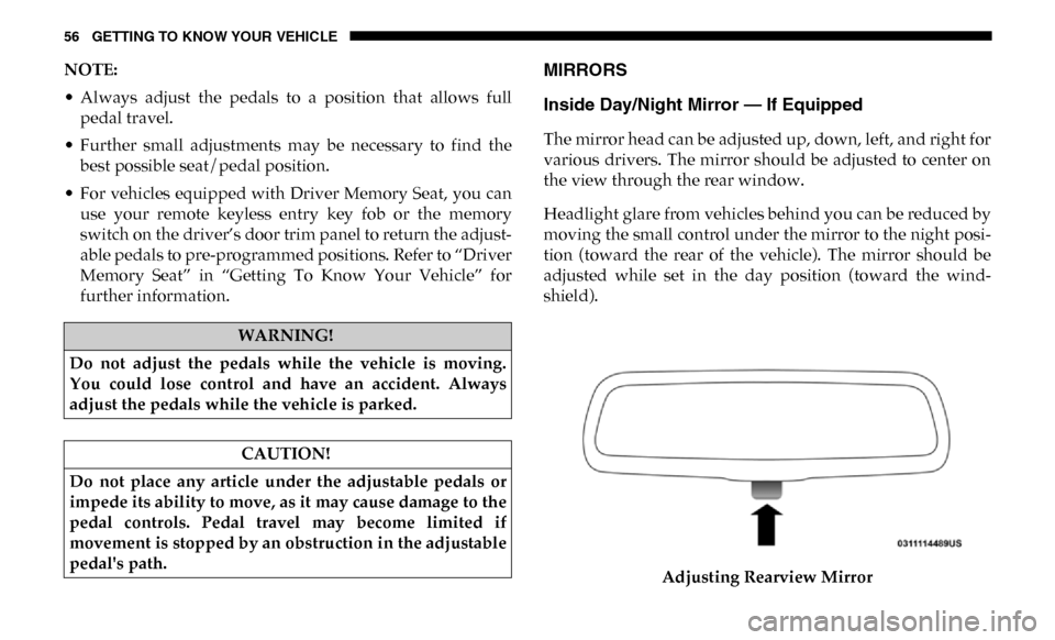
The mirror head can be adjusted up, down, left, and right for
various drivers. The mirror should be adjusted to center on
the view through the rear window.
Headlight glare from vehicles behind you can be reduced by
moving the small control under the mirror to the night posi -
tion (toward the rear of the vehicle). The mirror should be
adjusted while set in the day position (toward the wind -
shield).
Adjusting Rearview Mirror
WARNING!
Do not adjust the pedals while the vehicle is moving.
You could lose control and have an accident. Always
adjust the pedals while the vehicle is parked.
CAUTION!
Do not place any article under the adjustable pedals or
impede its ability to move, as it may cause damage to the
pedal controls. Pedal travel may become limited if
movement is stopped by an obstruction in the adjustable
pedal's path.
Page 61 of 607
GETTING TO KNOW YOUR VEHICLE 59
Driver's Outside Automatic Dimming Mirror — If
Equipped
The driver’s outside mirror will automatically adjust for
glare from vehicles behind you. This feature is controlled by
the inside automatic dimming mirror and will automatically
adjust for headlight glare when the inside mirror adjusts.
Power Mirrors — If Equipped
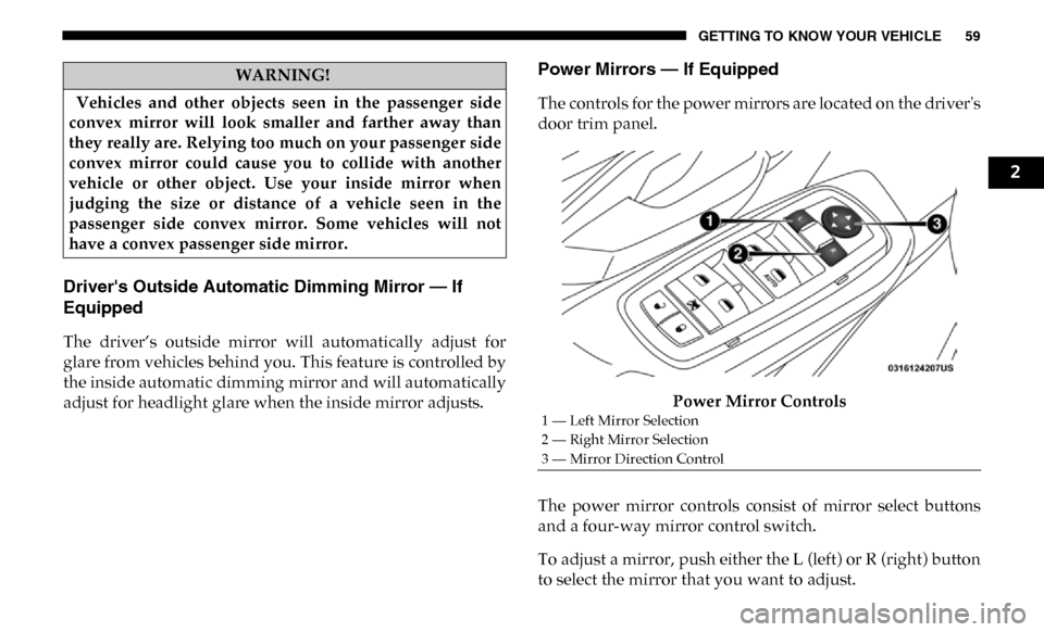
The controls for the power mirrors are located on the driver's
door trim panel.Power Mirror Controls
The power mirror controls consist of mirror select buttons
and a four-way mirror control switch.
To adjust a mirror, push either the L (left) or R (right) button
to select the mirror that you want to adjust.
WARNING!
Vehicles and other objects seen in the passenger side
convex mirror will look smaller and farther away than
they really are. Relying too much on your passenger side
convex mirror could cause you to collide with another
vehicle or other object. Use your inside mirror when
judging the size or distance of a vehicle seen in the
passenger side convex mirror. Some vehicles will not
have a convex passenger side mirror.
1 — Left Mirror Selection
2 — Right Mirror Selection
3 — Mirror Direction Control
2
Page 77 of 607

GETTING TO KNOW YOUR VEHICLE 75
Rotate the end of the lever upward, to the first detent past the
intermittent settings for low-speed wiper operation. Rotate
the end of the lever upward to the second detent past the
intermittent settings for high-speed wiper operation.
Intermittent Wiper System
The intermittent feature of this system was designed for use
when weather conditions make a single wiping cycle, with a
variable pause between cycles, desirable. For maximum
delay between cycles, rotate the control knob upward to the
first detent.
The delay interval decreases as you rotate the knob until it
enters the low continual speed position. The delay can be
regulated from a maximum of about 18 seconds between
cycles, to a cycle every one second. The delay intervals will
double in duration when the vehicle speed is 10 mph
(16 km/h) or less.
Windshield Washers
To use the windshield washer, push the washer knob,
located on the end of the multifunction lever, inward to the
second detent. Washer fluid will be sprayed and the wiper
will operate for two to three cycles after the washer knob is
released from this position.If the washer knob is depressed while in the delay range, the
wiper will operate for several seconds after the washer knob
is released. It will then resume the intermittent interval
previously selected. If the washer knob is pushed while in
the off position, the wiper will turn on and cycle approxi
-
mately three times after the wash knob is released.
To prevent freeze-up of your windshield washer system in
cold weather, select a solution or mixture that meets or
exceeds the temperature range of your climate. This rating
information can be found on most washer fluid containers.
WARNING!
Sudden loss of visibility through the windshield could
lead to a collision. You might not see other vehicles or
other obstacles. To avoid sudden icing of the windshield
during freezing weather, warm the windshield with the
defroster before and during windshield washer use.
2
Page 94 of 607
92 GETTING TO KNOW YOUR VEHICLE
WINDOWS
Power Windows
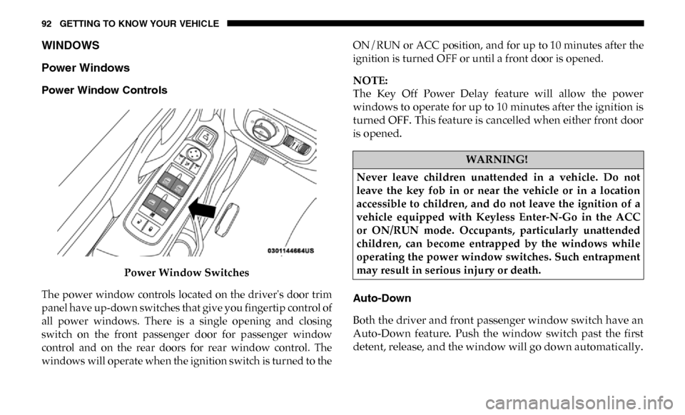
Power Window ControlsPower Window Switches
The power window controls located on the driver's door trim
panel have up-down switches that give you fingertip control of
all power windows. There is a single opening and closing
switch on the front passenger door for passenger window
control and on the rear doors for rear window control. The
windows will operate when the ignition switch is turned to the ON/RUN or ACC position, and for up to 10 minutes after the
ignition is turned OFF or until a front door is opened.
NOTE:
The Key Off Power Delay feature will allow the power
windows to operate for up to 10 minutes after the ignition is
turned OFF. This feature is cancelled when either front door
is opened.
Auto-Down
Both the driver and front passenger window switch have an
Auto-Down feature. Push the window switch past the first
detent, release, and the window will go down automatically.
WARNING!
Never leave children unattended in a vehicle. Do not
leave the key fob in or near the vehicle or in a location
accessible to children, and do not leave the ignition of a
vehicle equipped with Keyless Enter-N-Go in the ACC
or ON/RUN mode. Occupants, particularly unattended
children, can become entrapped by the windows while
operating the power window switches. Such entrapment
may result in serious injury or death.
Page 95 of 607

GETTING TO KNOW YOUR VEHICLE 93
To cancel the Auto-Down movement, operate the switch in
either the up or down direction and release the switch.
To stop the window from going all the way down during the
Auto-Down operation, pull up on the switch briefly.
To open the window part way, push to the switch to the first
detent and release it when you want the window to stop.
Auto-Up Feature With Anti-Pinch Protection — If
Equipped
Pull the window switch fully upward to the second detent,
release, and the window will go up automatically.
To stop the window from going all the way up during the
Auto-Up operation, push down on the switch briefly.
To close the window part way, lift the window switch to the
first detent and release when you want the window to stop.
NOTE:
If the window runs into any obstacle during the
Auto-Closure, it will reverse direction and then go back
down. Remove the obstacle and use the window switch
again to close the window. Any impact due to rough road
conditions may trigger the auto reverse function unexpect-edly during auto closure. If this happens, pull the switch
lightly to the first detent and hold to close the window manu-
ally.
Reset Auto-Up
Should the Auto-Up feature stop working, the window may
need to be reset. To reset Auto-Up:
1. Make sure the door is fully closed.
2. Pull the window switch up to close the window
completely and continue to hold the switch up for an
additional two seconds after the window is closed.
3. Push the window switch down firmly to the second detent to open the window completely and continue to
hold the switch down for an additional two seconds after
the window is fully open.
WARNING!
There is no anti-pinch protection when the window is
almost closed. Be sure to clear all objects from the
window before closing.
2