Running lights Ram 4500 Chassis Cab 2020 Owner's Manual
[x] Cancel search | Manufacturer: RAM, Model Year: 2020, Model line: 4500 Chassis Cab, Model: Ram 4500 Chassis Cab 2020Pages: 516, PDF Size: 29.24 MB
Page 5 of 516
3
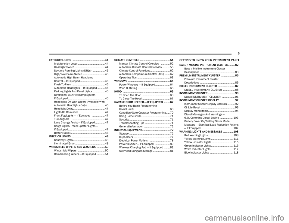
EXTERIOR LIGHTS ...............................................44 Multifunction Lever ...................................... 44
Headlight Switch .......................................... 44
Daytime Running Lights (DRLs) ................. 45
High/Low Beam Switch ............................... 45
Automatic High Beam Headlamp
Control — If Equipped .................................. 45 Flash-To-Pass ............................................. 46
Automatic Headlights — If Equipped .......... 46
Parking Lights And Panel Lights ................. 46
Directional LED Headlamp System —
If Equipped ................................................... 46 Headlights On With Wipers (Available With
Automatic Headlights Only) ......................... 46 Headlight Delay ............................................ 47
Lights-On Reminder ..................................... 47
Front Fog Lights — If Equipped .................. 47
Turn Signals ............................................. 47
Lane Change Assist — If Equipped ............. 47
Cargo Lights/Trailer Spotter Lights —
If Equipped ................................................... 47 Battery Saver................................................ 48
INTERIOR LIGHTS ................................................48
Courtesy Lights ............................................ 48
Illuminated Entry ......................................... 49
WINDSHIELD WIPERS AND WASHERS ............50
Windshield Wipers ..................................... 50
Rain Sensing Wipers — If Equipped ........... 51 CLIMATE CONTROLS ........................................... 51
Manual Climate Control Overview ............ 52
Automatic Climate Control Overview .......... 55
Climate Control Functions........................... 62
Automatic Temperature Control (ATC) ...... 62
Operating Tips ............................................. 63
WINDOWS ............................................................ 64
Power Windows — If Equipped .................... 64
Wind Buffeting ............................................ 66
HOOD .................................................................... 66
To Open The Hood ...................................... 66
To Close The Hood ....................................... 67
GARAGE DOOR OPENER — IF EQUIPPED ........ 67
Before You Begin Programming
HomeLink® .................................................. 68 Canadian/Gate Operator Programming ..... 70
Using HomeLink®........................................ 71
Security......................................................... 71
Troubleshooting Tips ................................... 71
General Information .................................... 72
INTERNAL EQUIPMENT ........................................ 72
Storage ......................................................... 72
Cupholders .................................................. 77
Electrical Power Outlets ............................ 78
Power Inverter — If Equipped ..................... 80
Wireless Charging Pad — If Equipped ........ 81
Overhead Sunglass Storage ....................... 81
GETTING TO KNOW YOUR INSTRUMENT PANEL
BASE / MIDLINE INSTRUMENT CLUSTER..........82Base / Midline Instrument Cluster
Descriptions ................................................. 83
PREMIUM INSTRUMENT CLUSTER .....................85
Premium Instrument Cluster
Descriptions ................................................. 86
DIESEL INSTRUMENT CLUSTER .........................87
DIESEL INSTRUMENT CLUSTER ................ 88
INSTRUMENT CLUSTER .......................................90
Diesel INSTRUMENT CLUSTER .................. 91
INSTRUMENT CLUSTER DISPLAY .......................92
Instrument Cluster Display Controls .......... 92
Oil Life Reset ............................................... 93
Display Menu Items ..................................... 94
Diesel Messages And Warnings —
6.7L Cummins Diesel Engine ................... 103 Battery Saver On/Battery Saver Mode
Message — Electrical Load Reduction Actions
— If Equipped .......................................... 107
WARNING LIGHTS AND MESSAGES ............... 108
Red Warning Lights ................................... 108
Yellow Warning Lights ............................... 111Yellow Indicator Lights .............................. 115
Green Indicator Lights ............................... 116White Indicator Lights ............................... 117Blue Indicator Lights ................................. 118
2020_RAM_CHASSIS_CAB_OM_USA=GUID-6C67832B-7839-4CCF-BEFC-CDF988F949EA=1=en=.book Page 3
Page 37 of 516
GETTING TO KNOW YOUR VEHICLE35
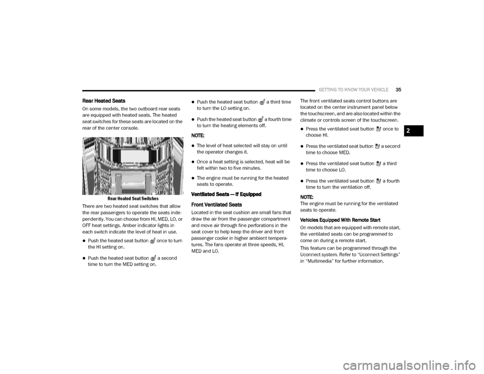
Rear Heated Seats
On some models, the two outboard rear seats
are equipped with heated seats. The heated
seat switches for these seats are located on the
rear of the center console.
Rear Heated Seat Switches
There are two heated seat switches that allow
the rear passengers to operate the seats inde -
pendently. You can choose from HI, MED, LO, or
OFF heat settings. Amber indicator lights in
each switch indicate the level of heat in use.
Push the heated seat button once to turn
the HI setting on.
Push the heated seat button a second
time to turn the MED setting on.
Push the heated seat button a third time
to turn the LO setting on.
Push the heated seat button a fourth time
to turn the heating elements off.
NOTE:
The level of heat selected will stay on until
the operator changes it.
Once a heat setting is selected, heat will be
felt within two to five minutes.
The engine must be running for the heated
seats to operate.
Ventilated Seats — If Equipped
Front Ventilated Seats
Located in the seat cushion are small fans that
draw the air from the passenger compartment
and move air through fine perforations in the
seat cover to help keep the driver and front
passenger cooler in higher ambient tempera -
tures. The fans operate at three speeds, HI,
MED and LO. The front ventilated seats control buttons are
located on the center instrument panel below
the touchscreen, and are also located within the
climate or controls screen of the touchscreen.
Press the ventilated seat button once to
choose HI.
Press the ventilated seat button a second
time to choose MED.
Press the ventilated seat button a third
time to choose LO.
Press the ventilated seat button a fourth
time to turn the ventilation off.
NOTE:
The engine must be running for the ventilated
seats to operate.
Vehicles Equipped With Remote Start
On models that are equipped with remote start,
the ventilated seats can be programmed to
come on during a remote start.
This feature can be programmed through the
Uconnect system. Refer to “Uconnect Settings”
in “Multimedia” for further information.
2
2020_RAM_CHASSIS_CAB_OM_USA=GUID-6C67832B-7839-4CCF-BEFC-CDF988F949EA=1=en=.book Page 35
Page 47 of 516
GETTING TO KNOW YOUR VEHICLE45
Daytime Running Lights (DRLs)
The headlights on your vehicle will illuminate
when the engine is started and the transmis -
sion is in any gear except PARK. This provides a
constant "lights on" condition until the ignition is
placed in the OFF position. The lights illuminate
at less than half of normal intensity. If the
parking brake is applied, the Daytime Running
Lights (DRLs) will turn off. Also, if a turn signal is
activated, the DRL lamp on the same side of the
vehicle may turn off for the duration of the turn
signal activation. Once the turn signal is no
longer active, the DRL lamp will illuminate.
NOTE:
If allowed by law in the country in which the
vehicle was purchased, the Daytime Running
Lights can be turned on and off using the
Uconnect System, refer to “Uconnect Settings”
in “Multimedia” for further information.
High/Low Beam Switch
Push the multifunction lever toward the instru-
ment panel to switch the headlights to high
beam. Pulling the multifunction lever back
toward the steering wheel will turn the low
beams back on, or shut the high beams off.
Automatic High Beam Headlamp Control —
If Equipped
The Automatic High Beam Headlamp Control
system provides increased forward lighting at
night by automating high beam control through
the use of a digital camera mounted on the
inside rearview mirror or forward facing camera.
This camera detects vehicle specific light and
automatically switches from high beams to low
beams until the approaching vehicle is out of
view.
NOTE:
The Automatic High Beam Headlamp Control
can be turned on or off by selecting “ON”
under “Auto Dim High Beams” within your
Uconnect settings, as well as turning the
headlight switch to the AUTO position. Refer
to “Uconnect Settings” in “Multimedia” for
further information.
Broken, muddy, or obstructed headlights and
taillights of vehicles in the field of view will
cause headlights to remain on longer (closer
to the vehicle). Also, dirt, film, and other
obstructions on the windshield or camera
lens will cause the system to function improp -
erly.
To opt out of the Advanced Auto High Beam
Sensitivity Control (default) and enter
Reduced High Beam Sensitivity Control (not
recommended), on vehicles equipped with
mirror controlled automatic high beams and
without the forward facing camera, toggle the
high beam lever six full on/off cycles within
10 seconds of placing the ignition in the ON
position. The system will return to the default
setting when the ignition is OFF.
If the windshield or Automatic High Beam Head -
lamp Control mirror is replaced, the mirror must
be re-aimed to ensure proper performance. See
a local authorized dealer.
To Activate
1. The Automatic High Beams are enabled through the Uconnect system. Refer to
“Uconnect Settings” in “Multimedia” for
further information.
2. Turn the headlight switch to the AUTO head -
light position.
3. Push the multifunction lever away from you (toward front of vehicle) to engage the high
beam mode.
2
2020_RAM_CHASSIS_CAB_OM_USA=GUID-6C67832B-7839-4CCF-BEFC-CDF988F949EA=1=en=.book Page 45
Page 48 of 516
46GETTING TO KNOW YOUR VEHICLE
NOTE:
The Automatic High Beams will not activate until
the vehicle is at or above 12 mph (20 km/h).
To Deactivate
1. Pull the multifunction lever toward you (or
rearward in vehicle) to manually deactivate
the system (normal operation of low
beams).
2. Push back on the multifunction lever to reactivate the system.
The Automatic High Beams can also be deacti -
vated through the Uconnect system. Refer to
“Uconnect Settings” in “Multimedia” for further
information.
Flash-To-Pass
You can signal another vehicle with your head -
lights by lightly pulling the multifunction lever
toward you. This will cause the high beam head -
lights to turn on, and remain on, until the lever
is released.
Automatic Headlights — If Equipped
This system automatically turns your headlights
on or off based on ambient light levels. To turn
the system on, turn the headlight switch clock-
wise, aligning the indicator with the AUTO on the
headlight switch. When the system is on, the
Headlight Time Delay feature is also on. This
means your headlights will stay on for up to 90
seconds after you place the ignition switch in
the OFF position. To turn the Automatic System
off, turn the headlight switch counterclockwise
to the O (off) position.
NOTE:
The engine must be running before the head -
lights will come on in the Automatic mode.
Parking Lights And Panel Lights
To turn on the parking lights and instrument
panel lights, from the O (off) position, rotate the
headlight switch clockwise to the first detent. To
turn off the parking lights, rotate the headlight
switch back to the O (off) position.
Directional LED Headlamp System — If
Equipped
This is a system consisting of LED (low/high
beam) headlights that incorporate dynamic
cornering with 5-degree inboard/15-degree
outboard swivel. The headlights continuously
and automatically adapt to the driving condi -
tions around bends or when cornering based on
steering wheel angle.
The system directs the headlights to light up the
road in the best way, taking into account the
speed of the vehicle and the bend or corner
angle, as well as the speed of steering.
The adaptive lights are automatically activated
when the vehicle is traveling above approxi -
mately 5 mph (8 km/h).
Headlights On With Wipers (Available With
Automatic Headlights Only)
When this feature is active, the headlights will
turn on approximately 10 seconds after the
wipers are turned on if the headlight switch is
placed in the AUTO position. In addition, the
headlights will turn off when the wipers are
turned off, if they were turned on by this feature.
2020_RAM_CHASSIS_CAB_OM_USA=GUID-6C67832B-7839-4CCF-BEFC-CDF988F949EA=1=en=.book Page 46
Page 101 of 516
GETTING TO KNOW YOUR INSTRUMENT PANEL99
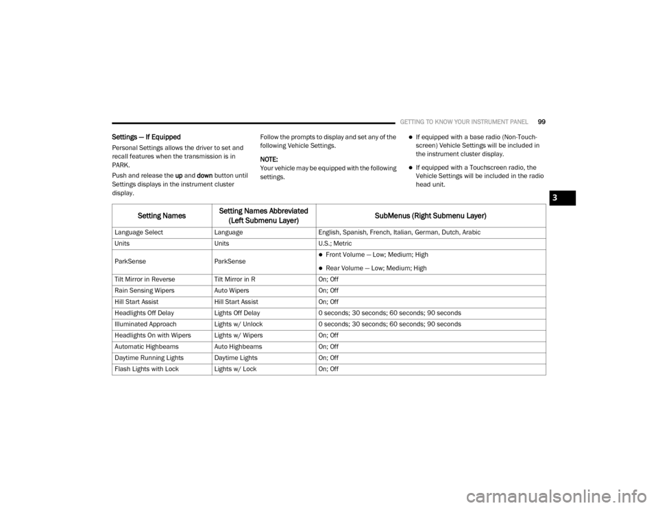
Settings — If Equipped
Personal Settings allows the driver to set and
recall features when the transmission is in
PARK.
Push and release the up and down button until
Settings displays in the instrument cluster
display. Follow the prompts to display and set any of the
following Vehicle Settings.
NOTE:
Your vehicle may be equipped with the following
settings.
If equipped with a base radio (Non-Touch
-
screen) Vehicle Settings will be included in
the instrument cluster display.
If equipped with a Touchscreen radio, the
Vehicle Settings will be included in the radio
head unit.
Setting Names Setting Names Abbreviated
(Left Submenu Layer) SubMenus (Right Submenu Layer)
Language Select
Language English, Spanish, French, Italian, German, Dutch, Arabic
Units Units U.S.; Metric
ParkSense ParkSense
Front Volume — Low; Medium; High
Rear Volume — Low; Medium; High
Tilt Mirror in Reverse Tilt Mirror in R On; Off
Rain Sensing Wipers Auto Wipers On; Off
Hill Start Assist Hill Start Assist On; Off
Headlights Off Delay Lights Off Delay 0 seconds; 30 seconds; 60 seconds; 90 seconds
Illuminated Approach Lights w/ Unlock 0 seconds; 30 seconds; 60 seconds; 90 seconds
Headlights On with Wipers Lights w/ Wipers On; Off
Automatic Highbeams Auto Highbeams On; Off
Daytime Running Lights Daytime Lights On; Off
Flash Lights with Lock Lights w/ Lock On; Off
3
2020_RAM_CHASSIS_CAB_OM_USA=GUID-6C67832B-7839-4CCF-BEFC-CDF988F949EA=1=en=.book Page 99
Page 109 of 516

GETTING TO KNOW YOUR INSTRUMENT PANEL107
Battery Saver On/Battery Saver Mode
Message — Electrical Load Reduction
Actions — If Equipped
This vehicle is equipped with an Intelligent
Battery Sensor (IBS) to perform additional moni-
toring of the electrical system and status of the
vehicle battery.
In cases when the IBS detects charging system
failure, or the vehicle battery conditions are
deteriorating, electrical load reduction actions
will take place to extend the driving time and
distance of the vehicle. This is done by reducing
power to or turning off non-essential electrical
loads.
Load reduction is only active when the engine is
running. It will display a message if there is a
risk of battery depletion to the point where the
vehicle may stall due to lack of electrical supply,
or will not restart after the current drive cycle.
When load reduction is activated, the message
“Battery Saver On Some Systems May Have
Reduced Power” will appear in the instrument
cluster.
These messages indicate the vehicle battery
has a low state of charge and continues to lose
electrical charge at a rate that the charging
system cannot sustain. NOTE:
The charging system is independent from
load reduction. The charging system
performs a diagnostic on the charging
system continuously.
If the Battery Charge Warning Light is on it
may indicate a problem with the charging
system. Refer to “Battery Charge Warning
Light” in “Getting To Know Your Instrument
Panel” for further information.
The electrical loads that may be switched off (if
equipped), and vehicle functions which can be
affected by load reduction:
Heated Seats/Vented Seats/Heated Wheel
Rear Defroster And Heated Mirrors
HVAC System
115 Volt AC Power Inverter System
Audio and Telematics System Loss of the battery charge may indicate one or
more of the following conditions:
The charging system cannot deliver enough
electrical power to the vehicle system
because the electrical loads are larger than
the capability of charging system. The
charging system is still functioning properly.
Turning on all possible vehicle electrical
loads (e.g. HVAC to max settings, exterior and
interior lights, overloaded power outlets
+12 Volts, 115 Volt AC, USB ports) during
certain driving conditions (city driving,
towing, frequent stopping).
Installing options like additional lights,
upfitter electrical accessories, audio
systems, alarms and similar devices.
Unusual driving cycles (short trips separated
by long parking periods).
The vehicle was parked for an extended
period of time (weeks, months).
The battery was recently replaced and was
not charged completely.
3
2020_RAM_CHASSIS_CAB_OM_USA=GUID-6C67832B-7839-4CCF-BEFC-CDF988F949EA=1=en=.book Page 107
Page 110 of 516
108GETTING TO KNOW YOUR INSTRUMENT PANEL
The battery was discharged by an electrical
load left on when the vehicle was parked.
The battery was used for an extended period
with the engine not running to supply radio,
lights, chargers, +12 Volt portable appli-
ances like vacuum cleaners, game consoles
and similar devices.
What to do when an electrical load reduction
action message is present (“Battery Saver On”
or “Battery Saver Mode”)
During a trip:
Reduce power to unnecessary loads if
possible:
Turn off redundant lights (interior or exte -
rior).
Check what may be plugged in to power outlets +12 Volts, 115 Volt AC, USB ports.
Check HVAC settings (blower, tempera -
ture).
Check the audio settings (volume). After a trip:
Check if any aftermarket equipment was
installed (additional lights, upfitter electrical
accessories, audio systems, alarms) and
review specifications if any (load and Ignition
Off Draw currents).
Evaluate the latest driving cycles (distance,
driving time and parking time).
The vehicle should have service performed if
the message is still present during consecu
-
tive trips and the evaluation of the vehicle
and driving pattern did not help to identify the
cause.
WARNING LIGHTS AND MESSAGES
The warning/indicator lights will illuminate in
the instrument panel together with a dedicated
message and/or acoustic signal when appli -
cable. These indications are indicative and
precautionary and as such must not be consid -
ered as exhaustive. Always refer to the informa-
tion in this chapter in the event of a failure
indication. All active telltales will display first if
applicable. The system check menu may
appear different based upon equipment
options and current vehicle status. Some tell -
tales are optional and may not appear.
Red Warning Lights
Seat Belt Reminder Warning Light
This warning light indicates when the
driver or passenger seat belt is
unbuckled. When the ignition is first
placed in the ON/RUN or ACC/ON/
RUN position and if the driver’s seat belt is
unbuckled, a chime will sound and the light will
turn on. When driving, if the driver or front
passenger seat belt remains unbuckled, the
Seat Belt Reminder Light will flash or remain on
continuously and a chime will sound.
Refer to “Occupant Restraint Systems” in
“Safety” for further information.
Air Bag Warning Light
This warning light will illuminate to
indicate a fault with the air bag, and
will turn on for four to eight seconds
as a bulb check when the ignition is
placed in the ON/RUN or ACC/ON/RUN posi -
tion. This light will illuminate with a single chime
when a fault with the air bag has been detected,
it will stay on until the fault is cleared. If the light
is either not on during startup, stays on, or turns
on while driving, have the system inspected at
an authorized dealer as soon as possible.
2020_RAM_CHASSIS_CAB_OM_USA=GUID-6C67832B-7839-4CCF-BEFC-CDF988F949EA=1=en=.book Page 108
Page 113 of 516
GETTING TO KNOW YOUR INSTRUMENT PANEL111
If the light continues to flash when the vehicle is
running, immediate service is required and you
may experience reduced performance, an
elevated/rough idle, or engine stall and your
vehicle may require towing. The light will come
on when the ignition is placed in the ON/RUN or
ACC/ON/RUN position and remain on briefly as
a bulb check. If the light does not come on
during starting, have the system checked by an
authorized dealer.
Electric Power Steering Fault Warning Light
This warning light will turn on when
there's a fault with the Electric Power
Steering (EPS) system. Refer to
“Power Steering” in “Starting And
Operating” for further information.
Trailer Brake Disconnected Warning Light
This warning light will illuminate when
the Trailer Brake has been discon -
nected.
Refer to “Trailer Towing” in “Starting And Oper -
ating” for further information.
Transmission Temperature Warning Light — If
Equipped
This warning light will illuminate to
warn of a high transmission fluid
temperature. This may occur with
strenuous usage such as trailer
towing. If this light turns on, stop the vehicle and
run the engine at idle or slightly faster, with the
transmission in PARK or NEUTRAL, until the
light turns off. Once the light turns off, you may
continue to drive normally.
Door Open Warning Light
This indicator will illuminate when a
door is ajar/open and not fully closed.
NOTE:
If the vehicle is moving there will also be a single
chime.
Yellow Warning Lights
Adaptive Cruise Control (ACC) Fault Warning
Light — If Equipped
This warning light will illuminate to
indicate a fault in the ACC system.
Contact a local authorized dealer for
service.
For further information, refer to “Adaptive
Cruise Control (ACC)” in “Starting And Oper -
ating.”
WARNING!
Continued operation with reduced assist
could pose a safety risk to yourself and
others. Service should be obtained as soon
as possible.WARNING!
If you continue operating the vehicle when
the Transmission Temperature Warning Light
is illuminated you could cause the fluid to boil
over, come in contact with hot engine or
exhaust components and cause a fire.
CAUTION!
Continuous driving with the Transmission
Temperature Warning Light illuminated will
eventually cause severe transmission
damage or transmission failure.
3
2020_RAM_CHASSIS_CAB_OM_USA=GUID-6C67832B-7839-4CCF-BEFC-CDF988F949EA=1=en=.book Page 111
Page 120 of 516
118GETTING TO KNOW YOUR INSTRUMENT PANEL
Blue Indicator Lights
High Beam Indicator Light
This indicator light will illuminate to
indicate that the high beam head -
lights are on. With the low beams acti -
vated, push the multifunction lever
forward (toward the front of the vehicle) to turn
on the high beams. Pull the multifunction lever
rearward (toward the rear of the vehicle) to turn
off the high beams. If the high beams are off,
pull the lever toward you for a temporary high
beam on, "flash to pass" scenario.
ONBOARD DIAGNOSTIC SYSTEM — OBD II
Your vehicle is equipped with a sophisticated
Onboard Diagnostic system called OBD II. This
system monitors the performance of the emis -
sions, engine, and transmission control
systems. When these systems are operating
properly, your vehicle will provide excellent
performance and fuel economy, as well as
engine emissions well within current govern -
ment regulations. If any of these systems require service, the OBD
II system will turn on the Malfunction Indicator
Light (MIL). It will also store diagnostic codes
and other information to assist your service
technician in making repairs. Although your
vehicle will usually be drivable and not need
towing, see an authorized dealer for service as
soon as possible.
Onboard Diagnostic System (OBD II)
Cybersecurity
Your vehicle is required to have an Onboard
Diagnostic system (OBD II) and a connection
port to allow access to information related to
the performance of your emissions controls.
Authorized service technicians may need to access this information to assist with the diag
-
nosis and service of your vehicle and emissions
system.
For further information, refer to “Cybersecurity”
in “Multimedia”.
CAUTION!
Prolonged driving with the MIL on could
cause further damage to the emission
control system. It could also affect fuel
economy and driveability. The vehicle must
be serviced before any emissions tests can
be performed.
If the MIL is flashing while the vehicle is
running, severe catalytic converter damage
and power loss will soon occur. Immediate
service is required.
WARNING!
ONLY an authorized service technician
should connect equipment to the OBD II
connection port in order to read the VIN,
diagnose, or service your vehicle.
If unauthorized equipment is connected to
the OBD II connection port, such as a
driver-behavior tracking device, it may:
Be possible that vehicle systems, including safety related systems, could
be impaired or a loss of vehicle control
could occur that may result in an acci -
dent involving serious injury or death.
Access, or allow others to access, infor -
mation stored in your vehicle systems,
including personal information.
2020_RAM_CHASSIS_CAB_OM_USA=GUID-6C67832B-7839-4CCF-BEFC-CDF988F949EA=1=en=.book Page 118
Page 160 of 516

158SAFETY
(Continued)
Enhanced Accident Response System
In the event of an impact, if the communication
network remains intact, and the power remains
intact, depending on the nature of the event,
the ORC will determine whether to have the
Enhanced Accident Response System perform
the following functions:
Cut off fuel to the engine (If Equipped)
Cut off battery power to the electric motor (If
Equipped)
Flash hazard lights as long as the battery has
power
Turn on the interior lights, which remain on
as long as the battery has power or for
15 minutes from the intervention of the
Enhanced Accident Response System.
Unlock the power door locks.
Your vehicle may also be designed to perform
any of these other functions in response to the
Enhanced Accident Response System:
Turn off the Fuel Filter Heater, Turn off the
HVAC Blower Motor, Close the HVAC Circula -
tion Door
Cut off battery power to the:
Engine
Electric Motor (if equipped)
Electric power steering
Brake booster
Electric park brake
Automatic transmission gear selector
Horn
Front wiper
Headlamp washer pump
NOTE:
After an accident, remember to place the igni -
tion to the STOP (OFF/LOCK) position and
remove the key from the ignition switch to avoid
draining the battery. Carefully check the vehicle
for fuel leaks in the engine compartment and on
the ground near the engine compartment and
fuel tank before resetting the system and
starting the engine. If there are no fuel leaks or
damage to the vehicle electrical devices (e.g.
headlights) after an accident, reset the system
by following the procedure described below. If
you have any doubt, contact an authorized
dealer.
Enhanced Accident Response System Reset
Procedure
In order to reset the Enhanced Accident
Response System functions after an event, the
ignition switch must be changed from ignition
START or ON/RUN to ignition OFF. Carefully
check the vehicle for fuel leaks in the engine
compartment and on the ground near the
engine compartment and fuel tank before reset -
ting the system and starting the engine.
Maintaining Your Air Bag System
WARNING!
Modifications to any part of the air bag
system could cause it to fail when you need
it. You could be injured if the air bag system
is not there to protect you. Do not modify
the components or wiring, including adding
any kind of badges or stickers to the
steering wheel hub trim cover or the upper
passenger side of the instrument panel. Do
not modify the front bumper, vehicle body
structure, or add aftermarket side steps or
running boards.
2020_RAM_CHASSIS_CAB_OM_USA=GUID-6C67832B-7839-4CCF-BEFC-CDF988F949EA=1=en=.book Page 158