Ram 5500 Chassis Cab 2011 Owner's Manual
Manufacturer: RAM, Model Year: 2011, Model line: 5500 Chassis Cab, Model: Ram 5500 Chassis Cab 2011Pages: 476, PDF Size: 7.32 MB
Page 131 of 476
NOTE:The driver’s heated seat can be programmed to
come on during a remote start. Refer to “Remote Starting
System — If Equipped” in “Things to Know Before
Starting Your Vehicle” for further information.
WARNING!
•Persons who are unable to feel pain to the skin
because of advanced age, chronic illness, diabetes,
spinal cord injury, medication, alcohol use, ex-
haustion or other physical condition must exercise
care when using the seat heater. It may cause burns
even at low temperatures, especially if used for
long periods of time.
(Continued)
WARNING! (Continued)
•Do not place anything on the seat that insulates
against heat, such as a blanket or cushion. This
may cause the seat heater to overheat. Sitting in a
seat that has been overheated could cause serious
burns due to the increased surface temperature of
the seat.
CAUTION!
Repeated overheating of the seat could damage the
heating element and/or degrade the material of the
seat.
130 UNDERSTANDING THE FEATURES OF YOUR VEHICLE
Page 132 of 476
Ventilated Seats — If Equipped
Located in the seat cushion and seatback are small fans
that draw the air from around the occupant and exhaust
it underneath the seat and into the passenger compart-
ment. The fans draw this air across the surface of the seat
using air ducts and fine perforations in the covering to
help keep the driver cooler in higher ambient tempera-
tures.
The ventilated seat switches are located in the switch
bank in the center stack of the instrument panel, just
below the climate controls. The fans operate at two
speeds, High and Low.Press the switch once to choose High,
press it a second time to choose Low.
Pressing the switch a third time will
turn the ventilated seat Off. When
High speed is selected both lights on the switch will be illuminated. When Low speed is
selected one light will be illuminated.
NOTE:
•The engine must be running for the ventilated seats to
operate.
•The driver’s ventilated seat can be programmed to
come on during a remote start. Refer to “Remote
Starting System — If Equipped” in “Things to Know
Before Starting Your Vehicle” for further information.
40-20-40 Front Bench Seat — If Equipped
The seat is divided into three segments. The outboard
seat portions are each 40% of the total width of the seat.
The back of the center portion (20%) easily folds down to
provide an armrest/center storage compartment (if
equipped).
3
UNDERSTANDING THE FEATURES OF YOUR VEHICLE 131
Page 133 of 476
DRIVER MEMORY SEAT — IF EQUIPPED
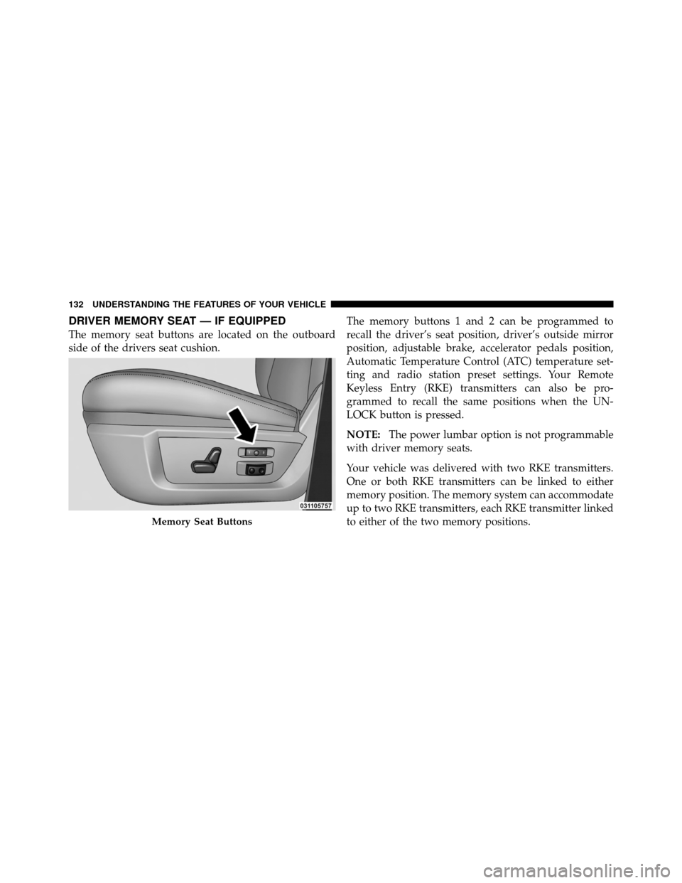
The memory seat buttons are located on the outboard
side of the drivers seat cushion.The memory buttons 1 and 2 can be programmed to
recall the driver’s seat position, driver’s outside mirror
position, adjustable brake, accelerator pedals position,
Automatic Temperature Control (ATC) temperature set-
ting and radio station preset settings. Your Remote
Keyless Entry (RKE) transmitters can also be pro-
grammed to recall the same positions when the UN-
LOCK button is pressed.
NOTE:
The power lumbar option is not programmable
with driver memory seats.
Your vehicle was delivered with two RKE transmitters.
One or both RKE transmitters can be linked to either
memory position. The memory system can accommodate
up to two RKE transmitters, each RKE transmitter linked
to either of the two memory positions.
Memory Seat Buttons
132 UNDERSTANDING THE FEATURES OF YOUR VEHICLE
Page 134 of 476

Setting Memory Positions and Linking RKE
Transmitter to Memory
NOTE:Each time the S (SET) button and a numbered
button (1 or 2) are pressed, you erase the memory settings
for that button and store new settings.
1. Turn the vehicle key to the ON/RUN position.
2. Adjust the driver’s seat, recliner, and both sideview
mirrors to the desired positions.
NOTE: Not all motors may be moved at one time. Refer
to “Seats/Eight-Way Power Seat” in this section for
further information.
3. Adjust the brake and accelerator pedals to the desired
positions.
4. Turn on the radio and set the radio station presets (up
to 10 AM and 10 FM stations can be set). 5. Adjust the Automatic Temperature Control (ATC)
while the ATC is in Auto mode.
6. Press and release the SET button located on the
driver’s seat.
7. Within five seconds, press and release MEMORY
button 1 or 2 on the driver’s seat. The next steps must be
performed within 10 seconds if you desire to also use a
RKE transmitter to recall memory positions.
8. Turn the ignition OFF and remove the key.
9. Press and release the LOCK button on one of the RKE
transmitters.
10. Repeat the above steps to set the next memory
position using the other numbered memory button or to
link another RKE transmitter to memory.
NOTE:
A chime sound may be heard if Setting Memory
was inhibited for any reason.
3
UNDERSTANDING THE FEATURES OF YOUR VEHICLE 133
Page 135 of 476

Memory Position Recall
NOTE:
•The vehicle must be in PARK to recall memory posi-
tions.
•Not all motors may be moved at one time. Refer to the
“Seats/Eight-Way Power Seat” in this section for fur-
ther information.
To recall the memory settings for driver one, press
MEMORY button number 1 on the driver’s seat or the
UNLOCK button on the RKE transmitter linked to
memory position 1.
To recall the memory setting for driver two, press
MEMORY button number 2 on the driver’s seat or the
UNLOCK button on the RKE transmitter linked to
memory position 2.
A recall can be cancelled by pressing any of the
MEMORY buttons on the driver’s seat during a recall (S, 1, or 2), or pressing any one of the power seat buttons,
pressing the adjustable pedals button, or pressing either
the LOCK or UNLOCK button on the RKE transmitter
when not in the ignition switch. When a recall is can-
celled, the driver’s seat and the pedals stop moving. A
delay of one second will occur before another recall can
be selected.
NOTE:
A chime sound may be heard if setting memory
was inhibited for any reason.
To Disable a RKE Transmitter Linked to Memory
1. Turn the ignition switch to the OFF position and
remove the key.
2. Press and release the memory SET button located on
the driver’s seat.
3. Within 10 seconds, press and release the UNLOCK
button on the RKE transmitter.
134 UNDERSTANDING THE FEATURES OF YOUR VEHICLE
Page 136 of 476

To disable another RKE transmitter linked to either
memory position, repeat Steps 1-3 for each RKE trans-
mitter.
NOTE:The capability to link RKE transmitters to
memory is enabled when delivered from the factory. The
capability to link RKE transmitters to memory can be
disabled (or later re-enabled) by an authorized dealer. For
vehicles equipped with the Electronic vehicle Informa-
tion Center (EVIC), refer to “Electronic Vehicle Informa-
tion Center (EVIC)/Customer-Programmable Features”
in “Understanding Your Instrument Panel” for further
information.
Self-Limiting Control
The memory system includes a self-limiting control for
full travel positioning of power seat and adjustable pedal
movement (all directions). This self-limiting control may,
however, develop an unintended movement limitation if
an obstruction is encountered sometime during usage. One example of such an occurrence may include a box or
package obstructing the full rearward movement of the
driver’s seat. Once the obstruction is removed, the self-
limiting control may store a new maximum position. the
self-limiting control may be reset by reaching the new
stored position, then press and release MEMORY button
1 or 2. Continued seat travel beyond the new stored
position will indicate the self-limiting control has been
reset.
Driver Easy Exit and Easy Entry Control
This additional feature provides automatic driver’s seat
positioning which will enhance driver mobility into and
out of the vehicle. The seat cushion will move rearward
approximately 2.5 in (60 mm) when the key is removed
from the ignition switch. The seat will move forward
approximately 2.5 in (60 mm) when the key is placed into
the ignition and turned out of the LOCK position. Each
stored memory setting will have an associated Easy Exit
and Easy Entry position. The Easy Exit and Easy Entry
3
UNDERSTANDING THE FEATURES OF YOUR VEHICLE 135
Page 137 of 476
feature may be automatically disabled if the seat is
positioned rearward enough and there is no benefit in
moving the seat any farther rearward.
NOTE:The Easy Entry/Easy Exit feature can be en-
abled or disabled through the programmable features in
the Electronic Vehicle Information Center (EVIC). Refer
to “Electronic Vehicle Information Center (EVIC)/
Customer-Programmable Features” in “Understanding
Your Instrument Panel” for further information.
TO OPEN AND CLOSE THE HOOD
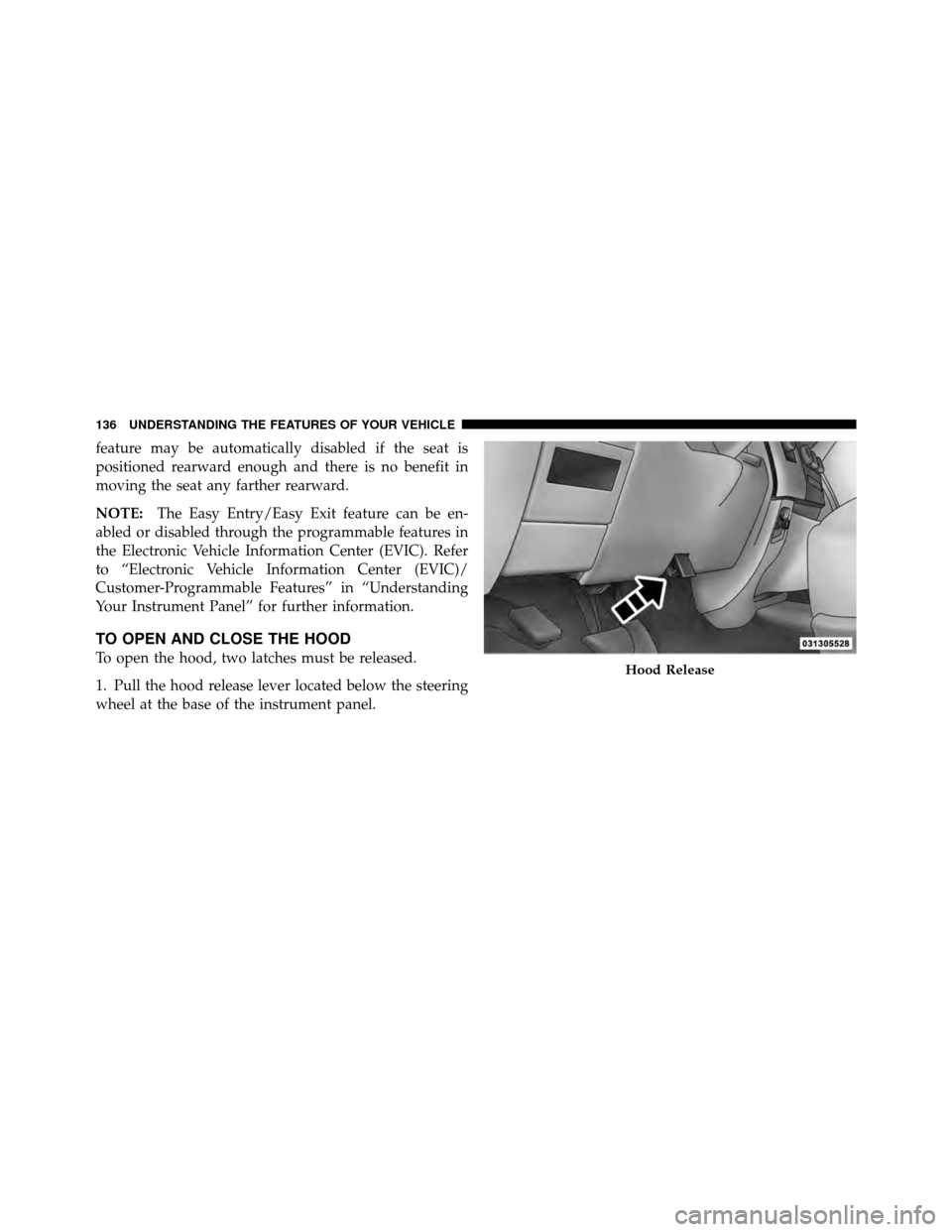
To open the hood, two latches must be released.
1. Pull the hood release lever located below the steering
wheel at the base of the instrument panel.Hood Release
136 UNDERSTANDING THE FEATURES OF YOUR VEHICLE
Page 138 of 476
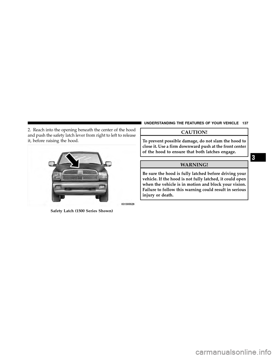
2. Reach into the opening beneath the center of the hood
and push the safety latch lever from right to left to release
it, before raising the hood.CAUTION!
To prevent possible damage, do not slam the hood to
close it. Use a firm downward push at the front center
of the hood to ensure that both latches engage.
WARNING!
Be sure the hood is fully latched before driving your
vehicle. If the hood is not fully latched, it could open
when the vehicle is in motion and block your vision.
Failure to follow this warning could result in serious
injury or death.
Safety Latch (1500 Series Shown)
3
UNDERSTANDING THE FEATURES OF YOUR VEHICLE 137
Page 139 of 476
LIGHTS
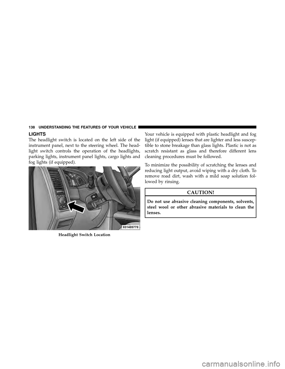
The headlight switch is located on the left side of the
instrument panel, next to the steering wheel. The head-
light switch controls the operation of the headlights,
parking lights, instrument panel lights, cargo lights and
fog lights (if equipped).Your vehicle is equipped with plastic headlight and fog
light (if equipped) lenses that are lighter and less suscep-
tible to stone breakage than glass lights. Plastic is not as
scratch resistant as glass and therefore different lens
cleaning procedures must be followed.
To minimize the possibility of scratching the lenses and
reducing light output, avoid wiping with a dry cloth. To
remove road dirt, wash with a mild soap solution fol-
lowed by rinsing.
CAUTION!
Do not use abrasive cleaning components, solvents,
steel wool or other abrasive materials to clean the
lenses.
Headlight Switch Location
138 UNDERSTANDING THE FEATURES OF YOUR VEHICLE
Page 140 of 476
Headlights
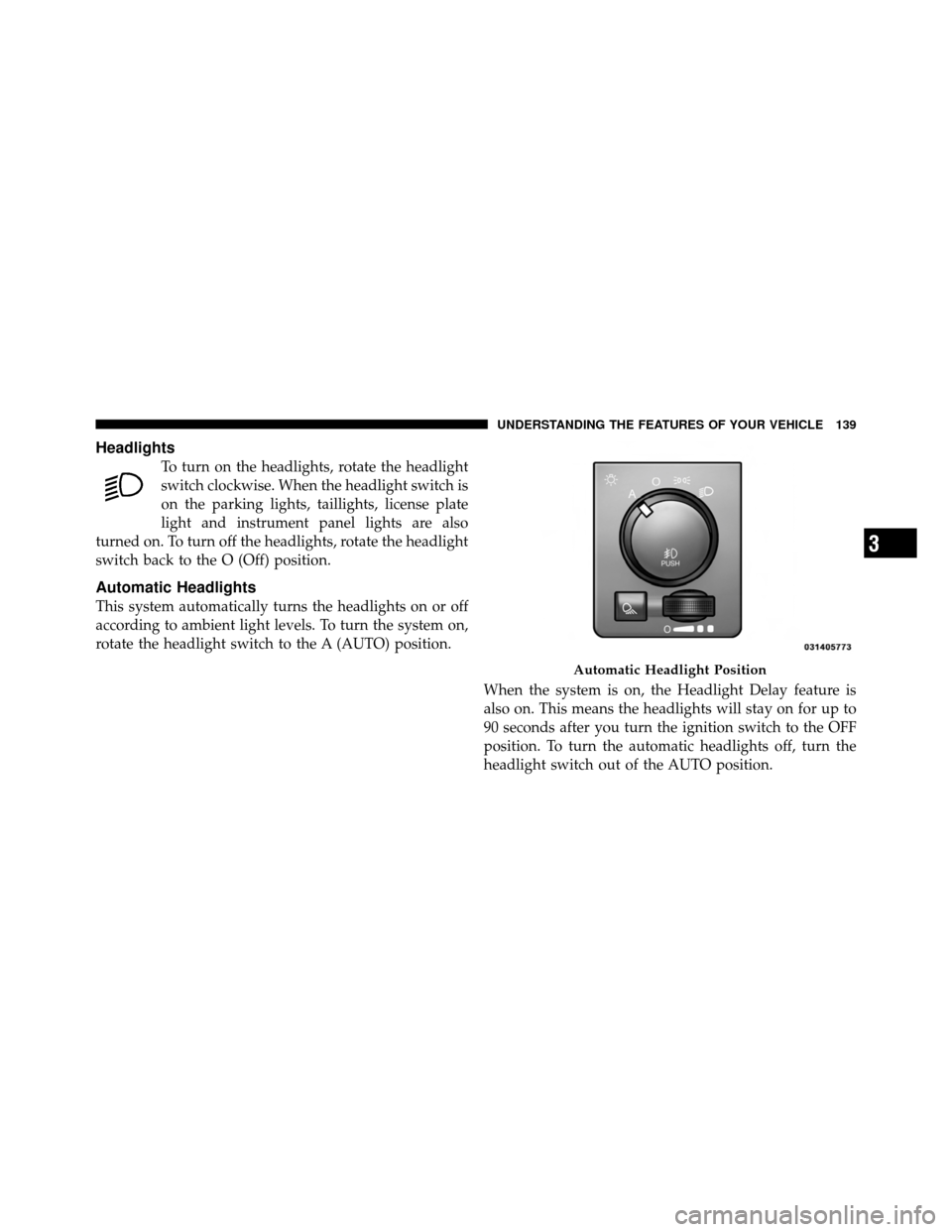
To turn on the headlights, rotate the headlight
switch clockwise. When the headlight switch is
on the parking lights, taillights, license plate
light and instrument panel lights are also
turned on. To turn off the headlights, rotate the headlight
switch back to the O (Off) position.
Automatic Headlights
This system automatically turns the headlights on or off
according to ambient light levels. To turn the system on,
rotate the headlight switch to the A (AUTO) position.
When the system is on, the Headlight Delay feature is
also on. This means the headlights will stay on for up to
90 seconds after you turn the ignition switch to the OFF
position. To turn the automatic headlights off, turn the
headlight switch out of the AUTO position.
Automatic Headlight Position
3
UNDERSTANDING THE FEATURES OF YOUR VEHICLE 139