clock Ram 5500 Chassis Cab 2012 User Guide
[x] Cancel search | Manufacturer: RAM, Model Year: 2012, Model line: 5500 Chassis Cab, Model: Ram 5500 Chassis Cab 2012Pages: 508, PDF Size: 7.01 MB
Page 266 of 508
Front Blower Control
There are four blower speeds. Use this
control to regulate the amount of air
forced through the system in any
mode you select. The blower speed
increases as you move the control
clockwise from the OFF position.
NOTE:For vehicles equipped with Remote Start, the
climate controls will not function during Remote Start
operation if the blower control is left in the OFF position.
Temperature Control
Use this control to regulate the tem-
perature of the air inside the passenger
compartment. Rotating the knob coun-
terclockwise, from top center into the
blue area of the scale, indicates coolertemperatures. Rotating the knob clockwise, into the red
area, indicates warmer temperatures.
NOTE:If your air conditioning performance seems
lower than expected, check the front of the A/C con-
denser (located in front of the radiator), for an accumu-
lation of dirt or insects. Clean with a gentle water spray
from behind the radiator and through the condenser.
Fabric front fascia protectors may reduce airflow to the
condenser, reducing air conditioning performance.
Mode Control (Air Direction)
Mode control allows you to choose
from several patterns of air distribu-
tion. You can select either a primary
mode, as identified by the symbols, or
a blend of two of these modes. The
closer the control is to a particular
mode, the more air distribution you
receive from that mode.
264 UNDERSTANDING YOUR INSTRUMENT PANEL
Page 272 of 508
blower will engage immediately if the Defrost mode is
selected, or by adjusting the blower control knob and
setting the fan to any fixed speed.
Manual Operation
This system offers a full complement of manual override
features.
NOTE:Each of these features operate independently
from each other. If any one feature is controlled manually,
the temperature doors will continue to operate automati-
cally.
There are six fixed blower speeds. Use
this control to regulate the amount of
air forced through the system in any
mode you select. The blower speed
increases as you move the control
clockwise from the OFF position.The blower fan speed can be set to any fixed speed by
adjusting the blower control knob. The fan will now
operate at a fixed speed until additional speeds are
selected. This allows the front occupants to control the
volume of air circulated in the vehicle and cancel the
Auto mode.
The operator can also select the direction of the airflow
by selecting one of the following positions.
Panel Mode
Air comes from the outlets in the instrument panel.
Each of these outlets can be individually adjusted to
direct the flow of air. The air vanes of the center outlets
and outboard outlets can be rotated to regulate or shut off
the airflow from these outlets.
Bi-Level Mode
Air comes from the instrument panel outlets, floor
outlets and defrost outlets.
Blower Control
270 UNDERSTANDING YOUR INSTRUMENT PANEL
Page 288 of 508

WARNING! (Continued)
•Your vehicle could move and injure you and others
if it is not completely in PARK. Check by trying to
move the shift lever clockwise without first pull-
ing it toward you after you have placed it in PARK.
Make sure the transmission is in PARK before
leaving the vehicle.
•It is dangerous to move the shift lever out of PARK
or NEUTRAL if the engine speed is higher than
idle speed. If your foot is not firmly pressing the
brake pedal, the vehicle could accelerate quickly
forward or in reverse. You could lose control of the
vehicle and hit someone or something. Only shift
into gear when the engine is idling normally and
when your foot is firmly pressing the brake pedal.
(Continued)
WARNING! (Continued)
•Unintended movement of a vehicle could injure
those in and near the vehicle. As with all vehicles,
you should never exit a vehicle while the engine is
running. Before exiting a vehicle, always apply the
parking brake, shift the transmission into PARK,
and remove the key fob. Once the key fob is
removed, the shift lever is locked in the PARK
position, securing the vehicle against unwanted
movement. Furthermore, you should never leave
unattended children inside a vehicle.
•Never leave children alone in a vehicle. Leaving
unattended children in a vehicle is dangerous for a
number of reasons. A child or others could be
seriously or fatally injured. Do not leave the key
fob in the vehicle. A child could operate power
windows, other controls, or move the vehicle.
286 STARTING AND OPERATING
Page 289 of 508
CAUTION!
•Before moving the shift lever out of PARK, you
must turn the ignition switch from the LOCK/OFF
position to the ON/RUN position, and also press
the brake pedal. Otherwise, damage to the shift
lever could result.
•DO NOT race the engine when shifting from
PARK or NEUTRAL into another gear range, as
this can damage the drivetrain.
The following indicators should be used to ensure that
you have engaged the shift lever into the PARK position:
•When shifting into PARK, pull the shift lever toward
you and move it all the way counterclockwise until it
stops.
•Release the shift lever and make sure it is fully seated
in the PARK gate.
•Look at the shift lever position display and verify that
it indicates the PARK position.
•With brake pedal released, verify that the shift lever
will not move out of PARK.
REVERSE
This range is for moving the vehicle rearward. Use this
range only after the vehicle has come to a complete stop.
NEUTRAL
Use this range when the vehicle is standing for prolonged
periods with the engine running. The engine may be
started in this range. Set the parking brake and shift the
transmission into PARK if you must leave the vehicle.
5
STARTING AND OPERATING 287
Page 386 of 508
WARNING! (Continued)
•If working on or near a roadway, be extremely
careful of motor traffic.
•To assure that spare tires, flat or inflated, are
securely stowed, spares must be stowed with the
valve stem facing the ground.
CAUTION!
Do not attempt to raise the vehicle by jacking on
locations other than those indicated in the Jacking
Instructions for this vehicle.
1. If equipped, remove the spare wheel, jack, and tools
from storage.
2. Using the wheel wrench, loosen, but do not remove,
the wheel nuts by turning them counterclockwise one
turn while the wheel is still on the ground.
3. When changing the front wheel, assemble the jack
drive tube to the jack and connect the drive tube to the
extension tube. Place the jack under the axle as close to
the tire as possible with the drive tubes extending to the
front. Connect the jack tube extension and wheel wrench.
Jack Warning Label
384 WHAT TO DO IN EMERGENCIES
Page 388 of 508

4. By rotating the wheel wrench clockwise, raise the
vehicle until the wheel just clears the surface.
WARNING!
Raising the vehicle higher than necessary can make
the vehicle unstable and cause a collision. It could
slip off the jack and hurt someone near it. Raise the
vehicle only enough to remove the tire.
5. Remove the wheel nuts and pull the wheel off. Install
the spare wheel and wheel nuts with the cone shaped end
of the nuts toward the wheel on single rear wheel (SRW)
models. On dual rear wheel models (DRW) the lug nuts
are a two-piece assembly with a flat face. Lightly tighten
the nuts. To avoid risk of forcing the vehicle off the jack,
do not fully tighten the nuts until the vehicle has been
lowered.6. Using the wheel wrench, finish tightening the nuts
using a crisscross pattern. The correct nut tightness is
135 ft lbs (183 N·m) torque for single rear wheel (SRW)
models and 145 ft lbs (197 N·m) for dual rear wheel
models. If in doubt about the correct tightness, have them
checked with a torque wrench by your authorized dealer
or at a service station.
WARNING!
A loose tire or jack thrown forward in a collision or
hard stop could injure someone in the vehicle. Al-
ways stow the jack parts and the extra tire and wheel
in the places provided.
7. Install wheel center cap (if equipped) and remove
wheel blocks. Do not install chrome or aluminum wheel
center caps on the spare wheel. This may result in cap
damage.
386 WHAT TO DO IN EMERGENCIES
Page 451 of 508
Fog Lamps – If Equipped
1. Reach under and behind the front bumper to access
the back of the front fog lamp housing.
2. Disconnect the fog lamp wiring harness connector
from the fog lamp bulb.
3. Rotate the bulb counterclockwise
1�4turn to unlock the
bulb from the housing.
4. Pull the bulb straight out from the housing.
CAUTION!
Do not contaminate the bulb glass by touching it
with your fingers or by allowing it to contact other
oily surfaces. Shortened bulb life will result.
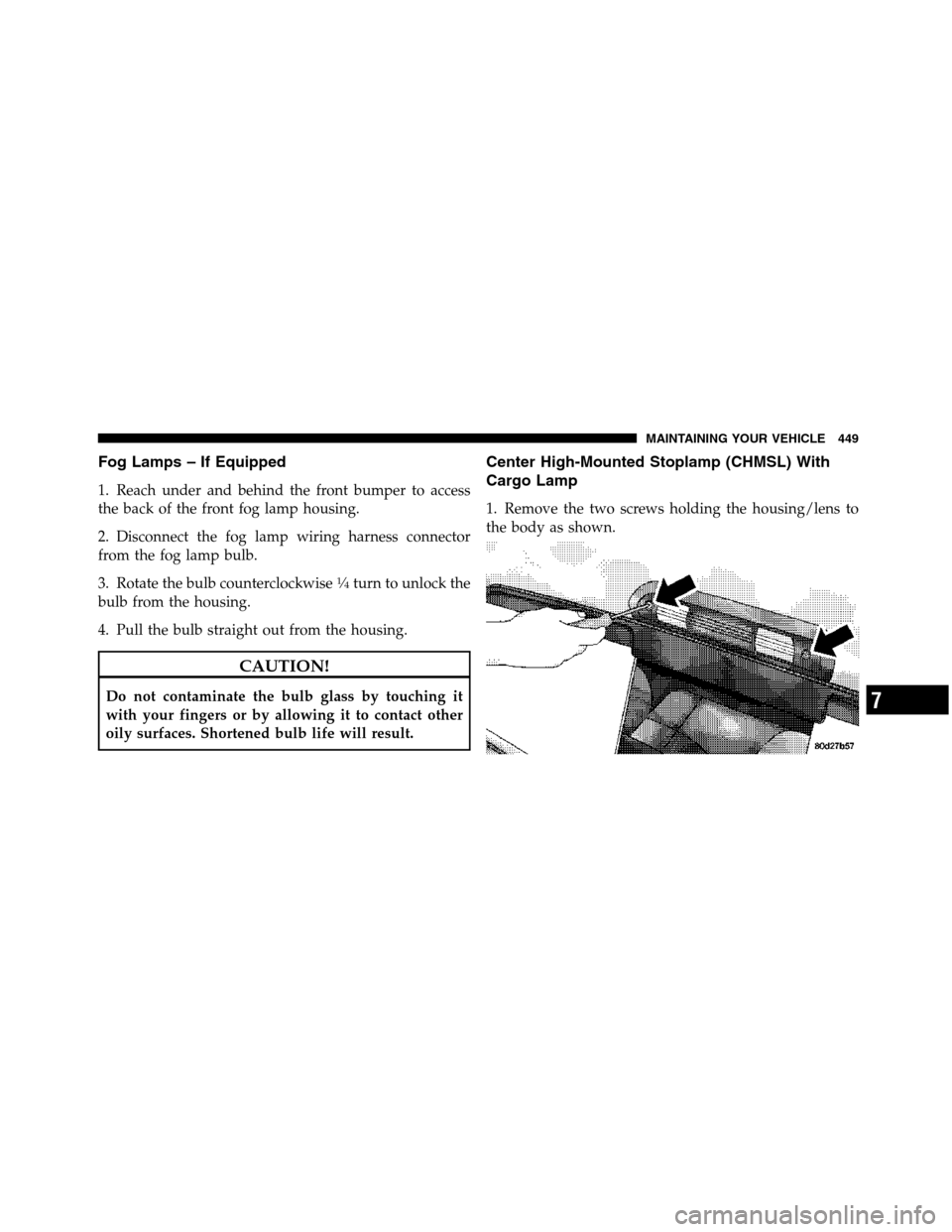
Center High-Mounted Stoplamp (CHMSL) With
Cargo Lamp
1. Remove the two screws holding the housing/lens to
the body as shown.
7
MAINTAINING YOUR VEHICLE 449
Page 490 of 508
Carbon Monoxide Warning............... 79,345
CargoLight ............................ 152
Cellular Phone........................ 93,262
Center High Mounted Stop Light............ 449
Center Lap Belts......................... 49
Center Seat Storage Compartment............ 176
Certification Label....................... 347
Chart, Tire Sizing........................ 316
Check Engine Light
(Malfunction Indicator Light).............200,407
Checking Your Vehicle For Safety............. 78
Checks, Safety........................... 78
Child Restraint.......................... 65
Child Restraint Tether Anchors............. 69,74
Child Seat............................ 65,71
Cigar Lighter........................... 169
Cleaning
Wheels............................ 437
Climate Control......................... 262Clock .............................225,234
Cold Weather Operation................... 280
Compact Disc (CD) Maintenance............. 262
Compact Spare Tire...................... 331
Compass.............................. 215
Compass Calibration..................... 216
Compass Variance....................... 217
Computer, Trip/Travel.................... 213
Connector
UCI .............................. 249
Universal Consumer Interface (UCI)....... 249
Console, Overhead....................... 163
Contract, Service........................ 479
Coolant Pressure Cap (Radiator Cap).......... 424
Cooling System......................... 421
Adding Coolant (Antifreeze)............. 423
Coolant Capacity..................... 453
Coolant Level....................421,425
Disposal of Used Coolant............... 425
488 INDEX
Page 500 of 508
Restraints, Occupant...................... 39
Rotation, Tires.......................... 339
Safety Checks Inside Vehicle................. 80
Safety Checks Outside Vehicle............... 82
Safety Defects, Reporting.................. 480
Safety Information, Tire................... 315
Safety Tips............................. 78
Safety, Exhaust Gas....................... 79
Satellite Radio (Uconnect™ studios)........... 256
Satellite Radio Antenna.................245,257
Schedule, Maintenance.................... 458
Seat Belt Maintenance.................... 440
Seat Belt Reminder....................... 52
Seat Belts.......................... 39,40,80
Adjustable Upper Shoulder Anchorage...... 49
And Pregnant Women.................. 53
Child Restraint..................... 65,68
Extender........................... 53Front Seat.......................... 40
Inspection.......................... 80
Reminder.......................... 203
Seats..............................129,141
Adjustment......................... 129
Child .............................. 68
Heated............................ 133
Memory........................... 141
Power............................ 129
Reclining .......................... 138
Security Alarm (Theft Alarm)................ 18
Selection of Coolant (Antifreeze)..........422,454
Sentry Key (Immobilizer)................... 16
Sentry Key Programming................... 18
Sentry Key Replacement................... 17
Service Assistance....................... 477
Service Contract......................... 479
Service Manuals........................ 481
SettingtheClock .....................225,234
498 INDEX