warning light Ram 5500 Chassis Cab 2012 User Guide
[x] Cancel search | Manufacturer: RAM, Model Year: 2012, Model line: 5500 Chassis Cab, Model: Ram 5500 Chassis Cab 2012Pages: 508, PDF Size: 7.01 MB
Page 109 of 508

Emergency Assistance
If you are in an emergency and the mobile phone is
reachable:
•Pick up the phone and manually dial the emergency
number for your area.
If the phone is not reachable and the Uconnect™ Phone is
operational, you may reach the emergency number as
follows:
•Press thebutton to begin.
•After the “Ready” prompt and the following beep, say
“Emergency” and the Uconnect™ Phone will instruct
the paired mobile phone to call the emergency num-
ber. This feature is supported in the U.S., Canada, and
Mexico.
NOTE:
•The emergency number dialed is based on the country
where the vehicle is purchased (911 for the U.S. andCanada and 060 for Mexico). The number dialed may
not be applicable with the available mobile service and
area.
•If supported, this number may be programmable on
some systems. To do this, press the
button and
say “Setup”, followed by “Emergency”.
•The Uconnect™ Phone does slightly lower your
chances of successfully making a phone call as to that
for the mobile phone directly.
WARNING!
To use your Uconnect™ Phone System in an emer-
gency, your mobile phone must be:
•turned on,
•paired to the Uconnect™ System,
•and have network coverage.
3
UNDERSTANDING THE FEATURES OF YOUR VEHICLE 107
Page 136 of 508

WARNING!
•Persons who are unable to feel pain to the skin
because of advanced age, chronic illness, diabetes,
spinal cord injury, medication, alcohol use, ex-
haustion or other physical condition must exercise
care when using the seat heater. It may cause burns
even at low temperatures, especially if used for
long periods of time.
•Do not place anything on the seat that insulates
against heat, such as a blanket or cushion. This
may cause the seat heater to overheat. Sitting in a
seat that has been overheated could cause serious
burns due to the increased surface temperature of
the seat.
Front Heated Seats
There are two heated seat switches that allow the driver
and passenger to operate the seats independently. Thecontrols for each seat are located near the bottom center
of the instrument panel (below the climate controls).
You can choose from HIGH, LOW or OFF heat settings.
Amber indicator lights in each switch indicate the level of
heat in use. Two indicator lights will illuminate for
HIGH, one for LOW and none for OFF.
Press the switch once to select HIGH-
level heating. Press the switch a sec-
ond time to select LOW-level heating.
Press the switch a third time to shut
the heating elements OFF.
NOTE:
•Once a heat setting is selected, heat will be felt within
two to five minutes.
•The engine must be running for the heated seats to
operate.
134 UNDERSTANDING THE FEATURES OF YOUR VEHICLE
Page 149 of 508
WARNING!
Be sure the hood is fully latched before driving your
vehicle. If the hood is not fully latched, it could open
when the vehicle is in motion and block your vision.
Failure to follow this warning could result in serious
injury or death.
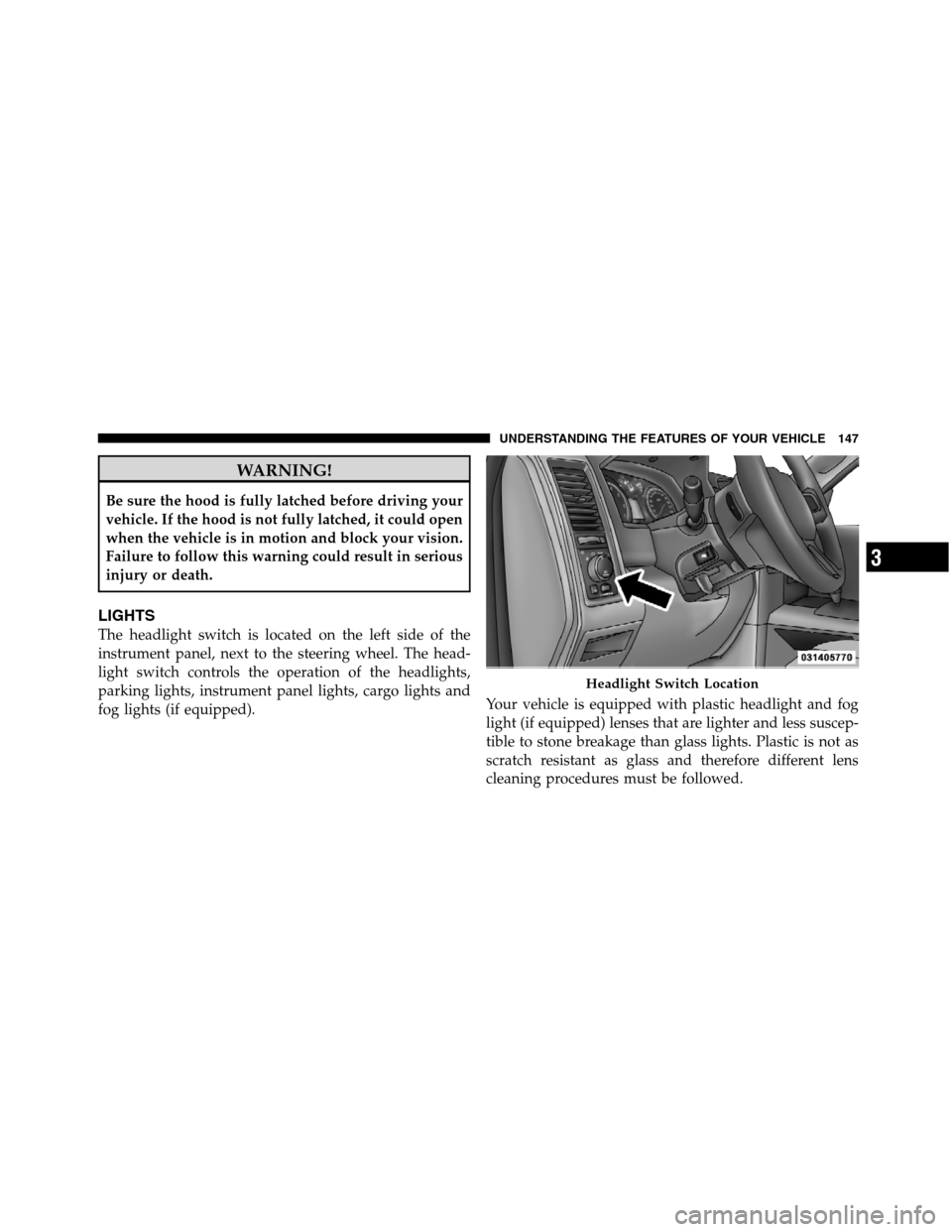
LIGHTS
The headlight switch is located on the left side of the
instrument panel, next to the steering wheel. The head-
light switch controls the operation of the headlights,
parking lights, instrument panel lights, cargo lights and
fog lights (if equipped).Your vehicle is equipped with plastic headlight and fog
light (if equipped) lenses that are lighter and less suscep-
tible to stone breakage than glass lights. Plastic is not as
scratch resistant as glass and therefore different lens
cleaning procedures must be followed.
Headlight Switch Location
3
UNDERSTANDING THE FEATURES OF YOUR VEHICLE 147
Page 161 of 508

be adjusted when the system is locked out (“Adjust-
able Pedal Disabled — Cruise Control Engaged” or
“Adjustable Pedal Disabled — Vehicle In Reverse”.
CAUTION!
Do not place any article under the adjustable pedals
or impede its ability to move as it may cause damage
to the pedal controls. Pedal travel may become lim-
ited if movement is stopped by an obstruction in the
adjustable pedal’s path.
WARNING!
Do not adjust the pedals while the vehicle is moving.
You could lose control and have an accident. Always
adjust the pedals while the vehicle is parked.
HEATED STEERING WHEEL — IF EQUIPPED
The steering wheel contains a heating element that helps
warm your hands in cold weather. The heated steering
wheel has only one temperature setting. Once the heated
steering wheel has been turned on it will operate for
approximately 58 to 70 minutes before automatically
shutting off. The heated steering wheel can shut off early
or may not turn on when the steering wheel is already
warm.
The heated steering wheel switch is located on the switch
bank below the climate controls.
Press the switch to turn on the heated
steering wheel. The light on the switch
will illuminate to indicate the steering
wheel heater is on. Pressing the switch
a second time will turn off the heated
steering wheel and light indicator.
3
UNDERSTANDING THE FEATURES OF YOUR VEHICLE 159
Page 163 of 508
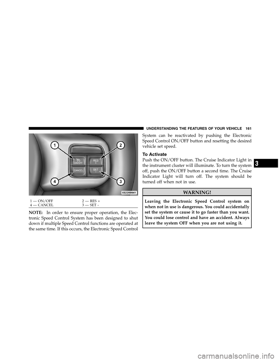
NOTE:In order to ensure proper operation, the Elec-
tronic Speed Control System has been designed to shut
down if multiple Speed Control functions are operated at
the same time. If this occurs, the Electronic Speed ControlSystem can be reactivated by pushing the Electronic
Speed Control ON/OFF button and resetting the desired
vehicle set speed.
To Activate
Push the ON/OFF button. The Cruise Indicator Light in
the instrument cluster will illuminate. To turn the system
off, push the ON/OFF button a second time. The Cruise
Indicator Light will turn off. The system should be
turned off when not in use.
WARNING!
Leaving the Electronic Speed Control system on
when not in use is dangerous. You could accidentally
set the system or cause it to go faster than you want.
You could lose control and have an accident. Always
leave the system OFF when you are not using it.1 — ON/OFF 2 — RES +
4 — CANCEL 3 — SET -
3
UNDERSTANDING THE FEATURES OF YOUR VEHICLE 161
Page 165 of 508
decrease until the button is released. Release the button
when the desired speed is reached, and the new set speed
will be established.
Pressing the SET (-) button once will result ina1mph
(1.6 km/h) decrease in set speed. Each subsequent tap of
the button results in a decrease of 1 mph (1.6 km/h).
To Accelerate For Passing
Press the accelerator as you would normally. When the
pedal is released, the vehicle will return to the set speed.
Using Electronic Speed Control On Hills
The transmission may downshift on hills to maintain the
vehicle set speed.
NOTE:The Electronic Speed Control system maintains
speed up and down hills. A slight speed change on
moderate hills is normal.On steep hills, a greater speed loss or gain may occur so
it may be preferable to drive without Electronic Speed
Control.
WARNING!
Electronic Speed Control can be dangerous where the
system cannot maintain a constant speed. Your ve-
hicle could go too fast for the conditions, and you
could lose control and have an accident. Do not use
Electronic Speed Control in heavy traffic or on roads
that are winding, icy, snow-covered or slippery.
OVERHEAD CONSOLE — IF EQUIPPED
The overhead console is located on the headliner above
the review mirror. The overhead console contains the
following features:
•Courtesy/Reading Lights
3
UNDERSTANDING THE FEATURES OF YOUR VEHICLE 163
Page 170 of 508
The key symbol indicates that this outlet can supply
power when the key is in the ON or ACC positions.
All accessories connected to the outlet(s) should be
removed or turned off when the vehicle is not in use to
protect the battery against discharge.
WARNING!
To avoid serious injury or death:
•Only devices designed for use in this type of
outlet should be inserted into any 12 Volt outlet.
•Do not touch with wet hands.
•Close the lid when not in use and while driving
the vehicle.
•If this outlet is mishandled, it may cause an
electric shock and failure.
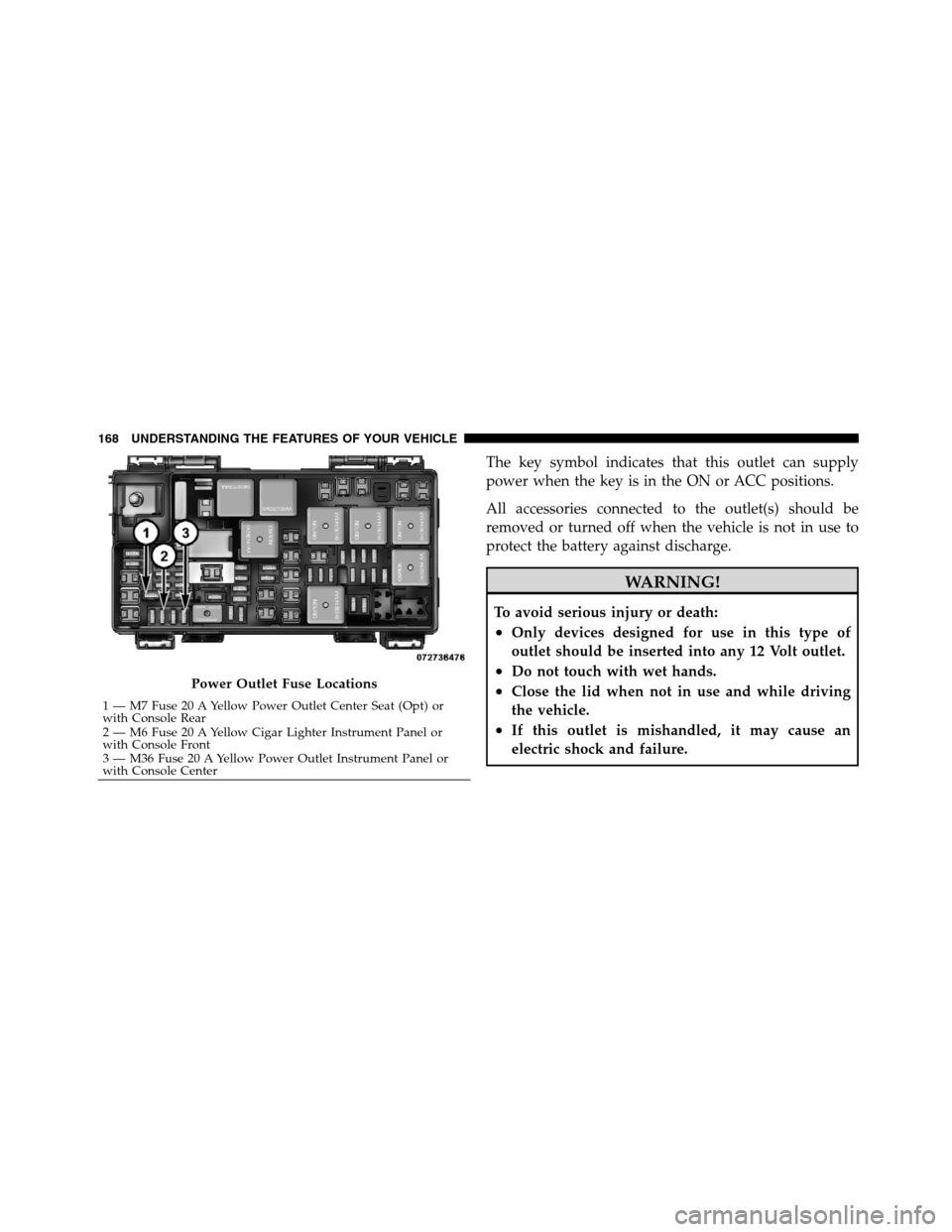
Power Outlet Fuse Locations
1 — M7 Fuse 20 A Yellow Power Outlet Center Seat (Opt) or
with Console Rear
2 — M6 Fuse 20 A Yellow Cigar Lighter Instrument Panel or
with Console Front
3 — M36 Fuse 20 A Yellow Power Outlet Instrument Panel or
with Console Center 168 UNDERSTANDING THE FEATURES OF YOUR VEHICLE
Page 197 of 508
NOTE:There is also an engine hour function. This
indicates the total number of hours the engine has been
running. To display the engine hours on the base cluster,
perform the following: Place the ignition in the ON/
RUN, but do not start the engine. With the odometer
value displayed, hold the TRIP button down for a period
of six seconds. The odometer will change to trip value
first, then it will display the engine hour value. The
engine hours will be displayed for a period of 30 seconds
until the ignition is turned OFF or the engine is started.
Some of the above warnings will be displayed in the
Electronic Vehicle Information Center (EVIC) Display
Area located in the instrument cluster. Refer to ”Elec-
tronic Vehicle Information Center (EVIC) — If Equipped”
for further information.
gASCAP
If the vehicle diagnostic system determines that the fuel
filler cap is loose, improperly installed, or damaged, aloose gascap indicator or the message “gASCAP” will
display in the odometer display area. Tighten the fuel
filler cap properly and press the TRIP button to turn off
the message. If the problem continues, the message will
appear the next time the vehicle is started.
A loose gas cap indicator will display in the Electronic
Vehicle Information Center (EVIC) for the premium
cluster (Refer to ”Electronic Vehicle InformationCenter
(EVIC) — If Equipped” for further information).
A loose, improperly installed, or damaged fuel filler cap
may also turn on the Malfunction Indicator Light (MIL).
noFUSE
If the vehicle diagnostic system determines that the
Ignition Off Draw (IOD) fuse is improperly installed, or
damaged, a “noFUSE” message will display in the odom-
eter display area. For further information on fuses and
fuse locations refer to “Fuses” in “Maintaining Your
Vehicle”.
4
UNDERSTANDING YOUR INSTRUMENT PANEL 195
Page 198 of 508
CHANgE OIL
Your vehicle is equipped with an engine oil change
indicator system. TheCHANgE OILmessage will flash
in the instrument cluster odometer for approximately
12 seconds after a single chime has sounded to indicate
the next scheduled oil change interval. The engine oil
change indicator system is duty cycle-based, which
means the engine oil change interval may fluctuate
dependent upon your personal driving style.
Unless reset, this message will continue to display each
time you turn the ignition switch to the ON/RUN
position. To turn off the message temporarily, press and
release the Trip Odometer button on the instrument
cluster. To reset the oil change indicator system (after
performing the scheduled maintenance), refer to the
following procedure:
1. Turn the ignition switch to the ON/RUN position
(do not start the engine).2. Fully depress the accelerator pedal slowly three
times within 10 seconds.
3. Turn the ignition switch to the OFF/LOCK position.
NOTE:If the indicator message illuminates when you
start the vehicle, the oil change indicator system did not
reset. If necessary, repeat this procedure.
15. Engine Temperature Warning Light
This light warns of an overheated engine condi-
tion. As temperatures rise and the gauge ap-
proachesH,this indicator will illuminate and a
single chime will sound after reaching a set threshold.
Further overheating will cause the temperature gauge to
passH,the indicator will continuously flash and a
continuous chime will occur until the engine is allowed
to cool.
If the light turns on while driving, safely pull over and
stop the vehicle. If the A/C system is on, turn it off. Also,
196 UNDERSTANDING YOUR INSTRUMENT PANEL
Page 200 of 508
19. Voltmeter — If Equipped
When the engine is running, the gauge indicates the
electrical system voltage. The pointer should stay within
the normal range if the battery is charged. If the pointer
moves to either extreme left or right and remains there
during normal driving, the electrical system should be
serviced.
NOTE:The voltmeter may show a gauge fluctuation at
various engine temperatures. This cycling operation is
caused by the post-heat cycle of the intake manifold
heater system. The number of cycles and the length of the
cycling operation is controlled by the engine control
module. Post-heat operation can run for several minutes,
and then the electrical system and voltmeter needle will
stabilize.20. Cargo Light
The cargo light will illuminate when the cargo
light is activated by pressing the cargo light
button on the headlight switch.
21. Brake Warning Light
This light monitors various brake functions,
including brake fluid level and parking brake
application. If the brake light turns on it may
indicate that the parking brake is applied, that
the brake fluid level is low, or that there is a problem with
the Anti-lock Brake System reservoir.
If the light remains on when the parking brake has been
disengaged, and the fluid level is at the full mark on the
master cylinder reservoir, it indicates a possible brake
hydraulic system malfunction or that a problem with the
Brake Booster has been detected by the Anti-Lock Brake
System (ABS). In this case, the light will remain on until
the condition has been corrected. If the problem is related
198 UNDERSTANDING YOUR INSTRUMENT PANEL