clock Ram Cargo Van 2012 User Guide
[x] Cancel search | Manufacturer: RAM, Model Year: 2012, Model line: Cargo Van, Model: Ram Cargo Van 2012Pages: 642, PDF Size: 9.7 MB
Page 379 of 642
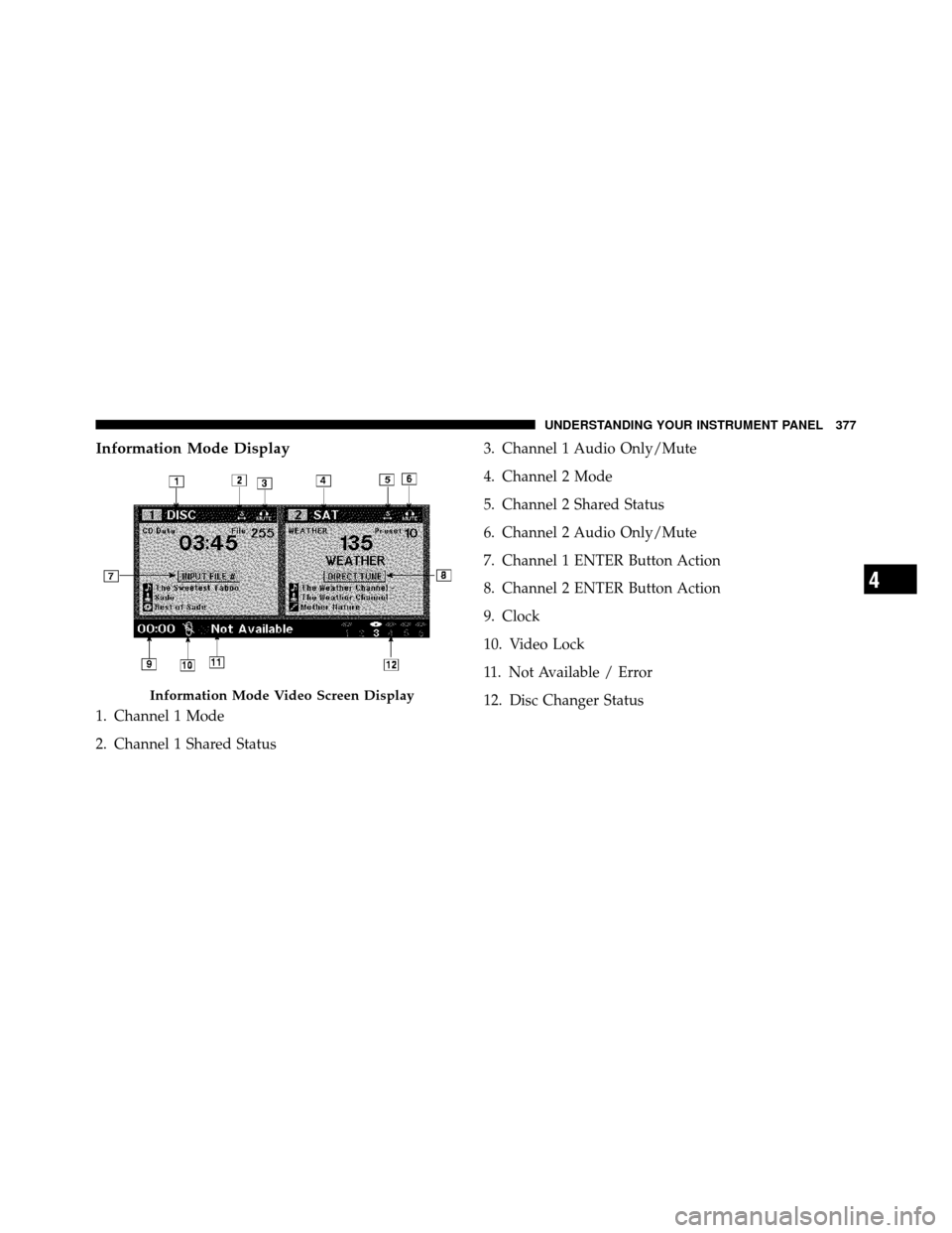
Information Mode Display
1. Channel 1 Mode
2. Channel 1 Shared Status3. Channel 1 Audio Only/Mute
4. Channel 2 Mode
5. Channel 2 Shared Status
6. Channel 2 Audio Only/Mute
7. Channel 1 ENTER Button Action
8. Channel 2 ENTER Button Action
9. Clock
10. Video Lock
11. Not Available / Error
12. Disc Changer Status
Information Mode Video Screen Display
4
UNDERSTANDING YOUR INSTRUMENT PANEL 377
Page 392 of 642
General Information
This system complies with Part 15 of the FCC Operation
is subject to the following two conditions:
1. This device may not cause harmful interference.
2. This device must accept any interference received,
including interference that may cause undesired
operation.STEERING WHEEL AUDIO CONTROLS — IF
EQUIPPED
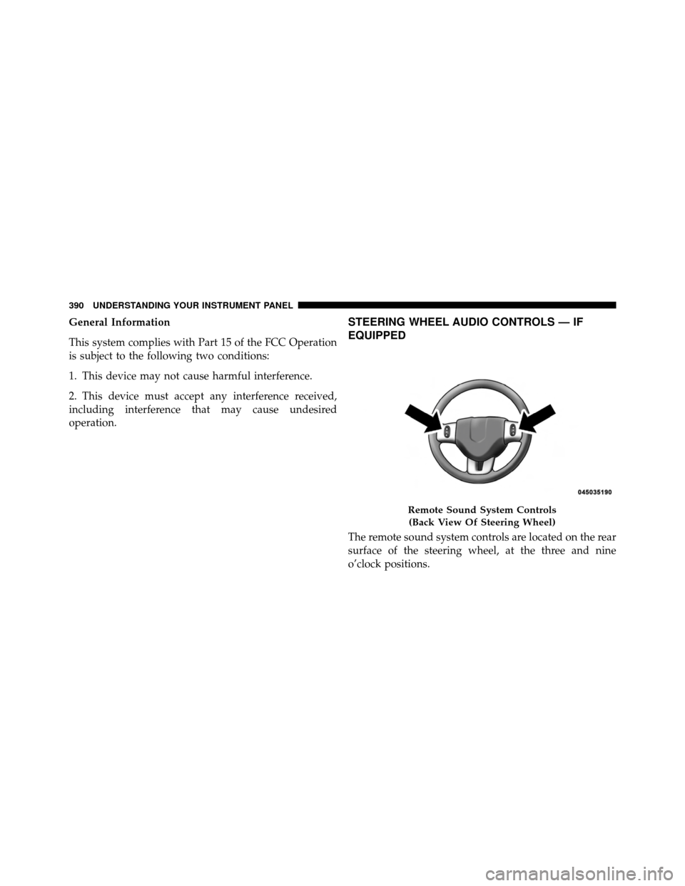
The remote sound system controls are located on the rear
surface of the steering wheel, at the three and nine
o’clock positions.
Remote Sound System Controls(Back View Of Steering Wheel)
390 UNDERSTANDING YOUR INSTRUMENT PANEL
Page 401 of 642
Rear Blower Control
The primary control for the rear blower is on the front
climate control unit, located on the instrument panel.
Only when the front control for the rear blower is in the
REARposition do the second row seat occupants have
control of the rear blower speed.
The rear blower control, located in the rear overhead
console, has an off position and a range of blower speeds.
This allows the second row seat occupants to control the
volume of air circulated in the rear of the vehicle.CAUTION!
Interior air enters the Rear Manual Climate Control
system through an intake grille, located in the right
side trim panel behind the third row seats. The
heater outlets are located in the right side trim panel,
just behind the sliding door. Do not block or place
objects directly in front of the inlet grille or heater
outlets. The electrical system could overload, causing
damage to the blower motor.
Rear Temperature Control
The rear mode selection REAR,allows the settings to be
controlled by the rear mode control knob.
To change the temperature in the rear of the vehicle,
rotate the temperature control knob counterclockwise for
cold air, and clockwise for heated air.
4
UNDERSTANDING YOUR INSTRUMENT PANEL 399
Page 407 of 642
customer-programmable feature. Refer to the “Elec-
tronic Vehicle Information Center (EVIC) — Customer-
Programmable Features” in this Section.
To provide you with maximum comfort in the automatic
mode, during cold start-ups, the blower fan will remain
on low until the engine warms up. The fan will engage
immediately if the Defrost mode is selected, or by chang-
ing the front blower knob setting
Manual Operation
This system offers a full complement of manual override
features. The AUTO symbol in the front ATC display will
be turned off when the system is being used in the
manual mode.
NOTE: Each of these features operate independently
from each other. If any one feature is controlled manually,
the temperature doors will continue to operate automati-
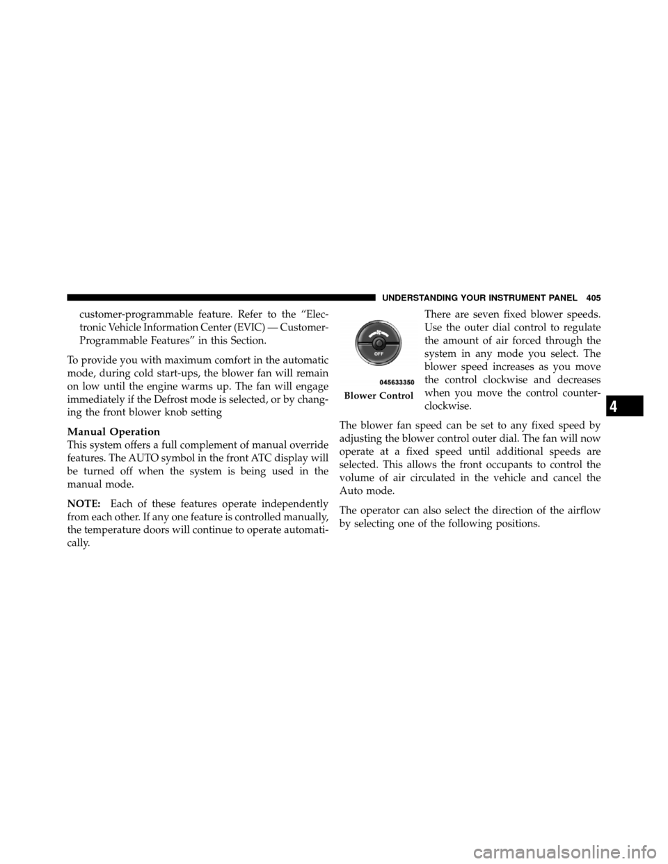
cally. There are seven fixed blower speeds.
Use the outer dial control to regulate
the amount of air forced through the
system in any mode you select. The
blower speed increases as you move
the control clockwise and decreases
when you move the control counter-
clockwise.
The blower fan speed can be set to any fixed speed by
adjusting the blower control outer dial. The fan will now
operate at a fixed speed until additional speeds are
selected. This allows the front occupants to control the
volume of air circulated in the vehicle and cancel the
Auto mode.
The operator can also select the direction of the airflow
by selecting one of the following positions.
Blower Control
4
UNDERSTANDING YOUR INSTRUMENT PANEL 405
Page 411 of 642
1. Press the Rear Temperature Lock button on the front
ATC panel. This turns off the Rear Temperature Lock icon
in the rear temperature knob.
2. Rotate the Rear Blower, Rear Temperature and the
Rear Mode Control knobs to suit your comfort needs.
3. ATC is selected by adjusting the rear blower knob
counterclockwise to AUTO.
Once the desired temperature is displayed, the ATC
System will automatically achieve and maintain that
comfort level. When the system is set up for your comfort
level, it is not necessary to change the settings. You will
experience the greatest efficiency by simply allowing the
system to function automatically.NOTE:
•It is not necessary to move the temperature settings for
cold or hot vehicles. The system automatically adjusts
the temperature, mode and fan speed to provide
comfort as quickly as possible.
•The temperature can be displayed in English or Metric
units by selecting the “Display Units of Measure in”
customer-programmable feature. Refer to the “Elec-
tronic Vehicle Information Center (EVIC) — Customer-
Programmable Features” in this Section.
4
UNDERSTANDING YOUR INSTRUMENT PANEL 409
Page 412 of 642
Rear Blower Control
The rear blower control knob can be manually set to off,
or any fixed blower speed, by rotating the knob from low
to high. This allows the rear seat occupants to control the
volume of air circulated in the rear of the vehicle.
CAUTION!
Interior air enters the Rear Automatic Temperature
Control System through an intake grille, located in
the right side trim panel behind the third row seats.
The heater outlets are located in the right side trim
panel, just behind the sliding door. Do not block or
place objects directly in front of the inlet grille or
heater outlets. The electrical system could overload
causing damage to the blower motor.
Rear Temperature Control
To change the temperature in the rear of the vehicle,
rotate the temperature knob counterclockwise to lower
the temperature, and clockwise to increase the tempera-
ture. The rear temperature settings are displayed in the
front ATC panel.
When rear controls are locked by the front system, the
Rear Temperature Lock symbol on the temperature knob
is illuminated and any rear overhead adjustments are
ignored.
Rear Mode Control
Auto Mode
The rear system automatically maintains the correct
mode and comfort level desired by the rear seat occu-
pants.
410 UNDERSTANDING YOUR INSTRUMENT PANEL
Page 533 of 642
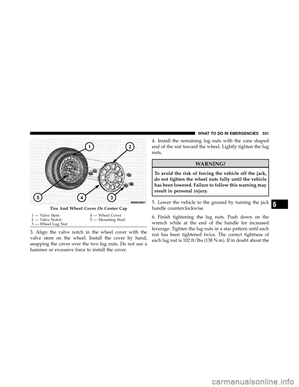
3. Align the valve notch in the wheel cover with the
valve stem on the wheel. Install the cover by hand,
snapping the cover over the two lug nuts. Do not use a
hammer or excessive force to install the cover.4. Install the remaining lug nuts with the cone shaped
end of the nut toward the wheel. Lightly tighten the lug
nuts.
WARNING!
To avoid the risk of forcing the vehicle off the jack,
do not tighten the wheel nuts fully until the vehicle
has been lowered. Failure to follow this warning may
result in personal injury.
5. Lower the vehicle to the ground by turning the jack
handle counterclockwise.
6. Finish tightening the lug nuts. Push down on the
wrench while at the end of the handle for increased
leverage. Tighten the lug nuts in a star pattern until each
nut has been tightened twice. The correct tightness of
each lug nut is 102 ft/lbs (138 N·m). If in doubt about the
Tire And Wheel Cover Or Center Cap
1 — Valve Stem 4 — Wheel Cover
2 — Valve Notch 5 — Mounting Stud
3 — Wheel Lug Nut
6
WHAT TO DO IN EMERGENCIES 531
Page 534 of 642
correct tightness, have them checked with a torque
wrench by your authorized dealer or service station.
7. After 25 miles (40 km) check the lug nut torque with a
torque wrench to ensure that all lug nuts are properly
seated against the wheel.
Vehicles Without Wheel Covers
1. Mount the road tire on the axle.
2. Install the remaining lug nuts with the cone shaped
end of the nut toward the wheel. Lightly tighten the lug
nuts.
WARNING!
To avoid the risk of forcing the vehicle off the jack,
do not tighten the wheel nuts fully until the vehicle
has been lowered. Failure to follow this warning may
result in personal injury.3. Lower the vehicle to the ground by turning the jack
handle counterclockwise.
4. Finish tightening the lug nuts. Push down on the
wrench while at the end of the handle for increased
leverage. Tighten the lug nuts in a star pattern until each
nut has been tightened twice. The correct tightness of
each lug nut is 102 ft/lbs (138 N·m). If in doubt about the
correct tightness, have them checked with a torque
wrench by your authorized dealer or service station.
5. After 25 miles (40 km) check the lug nut torque with a
torque wrench to ensure that all lug nuts are properly
seated against the wheel.JUMP-STARTING PROCEDURE
If your vehicle has a discharged battery it can be jump-
started using a set of jumper cables and a battery in
another vehicle or by using a portable battery booster
pack. Jump-starting can be dangerous if done improperly
so please follow the procedures in this section carefully.
532 WHAT TO DO IN EMERGENCIES
Page 584 of 642
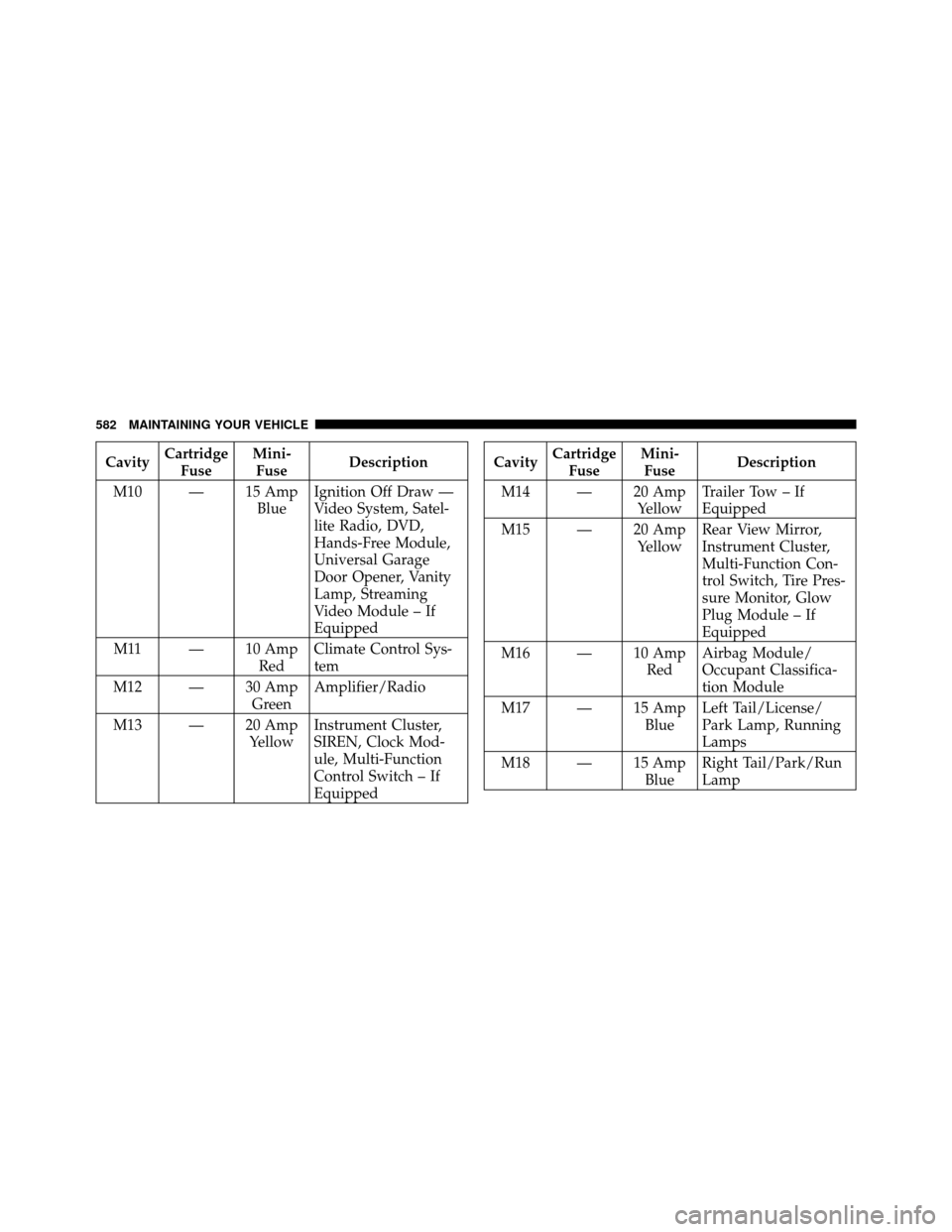
CavityCartridge
Fuse Mini-
Fuse Description
M10 — 15 Amp BlueIgnition Off Draw —
Video System, Satel-
lite Radio, DVD,
Hands-Free Module,
Universal Garage
Door Opener, Vanity
Lamp, Streaming
Video Module – If
Equipped
M11 — 10 Amp RedClimate Control Sys-
tem
M12 — 30 Amp GreenAmplifier/Radio
M13 — 20 Amp YellowInstrument Cluster,
SIREN, Clock Mod-
ule, Multi-Function
Control Switch – If
EquippedCavity
Cartridge
Fuse Mini-
Fuse Description
M14 — 20 Amp YellowTrailer Tow – If
Equipped
M15 — 20 Amp YellowRear View Mirror,
Instrument Cluster,
Multi-Function Con-
trol Switch, Tire Pres-
sure Monitor, Glow
Plug Module – If
Equipped
M16 — 10 Amp RedAirbag Module/
Occupant Classifica-
tion Module
M17 — 15 Amp BlueLeft Tail/License/
Park Lamp, Running
Lamps
M18 — 15 Amp BlueRight Tail/Park/Run
Lamp
582 MAINTAINING YOUR VEHICLE
Page 624 of 642
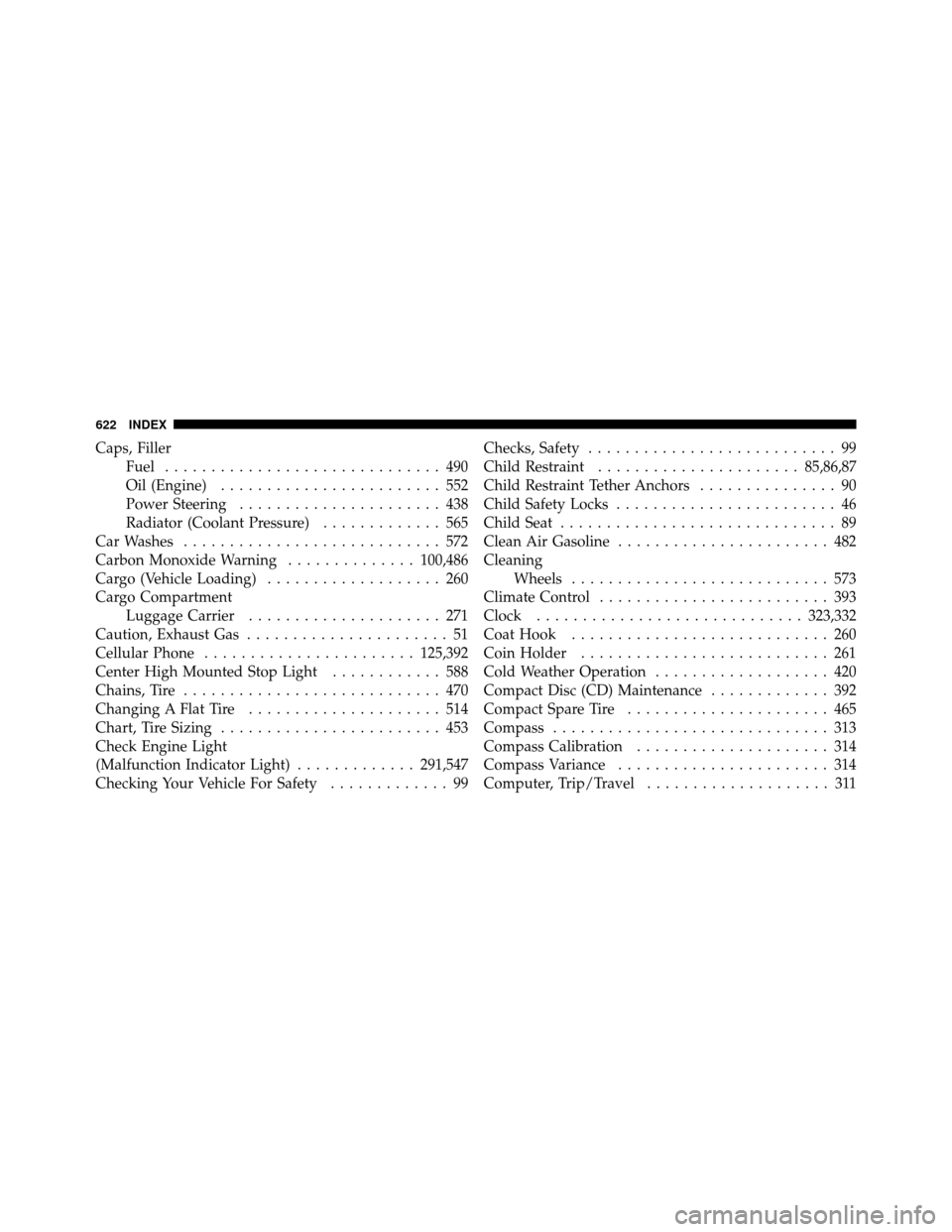
Caps, FillerFuel .............................. 490
Oil (Engine) ........................ 552
Power Steering ...................... 438
Radiator (Coolant Pressure) ............. 565
Car Washes ............................ 572
Carbon Monoxide Warning ..............100,486
Cargo (Vehicle Loading) ................... 260
Cargo Compartment Luggage Carrier ..................... 271
Caution, Exhaust Gas ...................... 51
Cellular Phone ....................... 125,392
Center High Mounted Stop Light ............ 588
Chains, Tire ............................ 470
Changing A Flat Tire ..................... 514
Chart, Tire Sizing ........................ 453
Check Engine Light
(Malfunction Indicator Light) .............291,547
Checking Your Vehicle For Safety ............. 99Checks, Safety
........................... 99
Child Restraint ...................... 85,86,87
Child Restraint Tether Anchors ............... 90
Child Safety Locks ........................ 46
Child Seat .............................. 89
Clean Air Gasoline ....................... 482
Cleaning Wheels ............................ 573
Climate Control ......................... 393
Clock ............................. 323,332
Coat Hook ............................ 260
Coin Holder ........................... 261
Cold Weather Operation ................... 420
Compact Disc (CD) Maintenance ............. 392
Compact Spare Tire ...................... 465
Compass .............................. 313
Compass Calibration ..................... 314
Compass Variance ....................... 314
Computer, Trip/Travel .................... 311
622 INDEX