ECU RAM CHASSIS CAB 2009 User Guide
[x] Cancel search | Manufacturer: RAM, Model Year: 2009, Model line: CHASSIS CAB, Model: RAM CHASSIS CAB 2009Pages: 429, PDF Size: 3.51 MB
Page 65 of 429

Allow the belt to return to the retractor, pulling on the
excess webbing to tighten the lap portion about the
child restraint. Refer to\6Automatic Locking Retractors
(ALR) Mode\6 in this section.
•In the rear seat, you may have trouble tightening the
lap/shoulder belt on the child restraint because the
buckle or latch plate is too close to the belt path
opening on the restraint. Disconnect the latch plate
from the buckle and twist the short buckle-end belt
several times to shorten it. Insert the latch plate into
the buckle with the release button facing out.
•If the belt still can’t be tightened, or if pulling and
pushing on the restraint loosens the belt, disconnect
the latch plate from the buckle, turn the latch plate
around, and insert the latch plate into the buckle
again. If you still can’t make the child restraint secure,
try a different seating position.
•Buckle the child into the seat according to the child
restraint manufacturer’s directions.
•When your child restraint is not in use, secure it in the
vehicle with the seat belt or remove it from the vehicle.
Do not leave it loose in the vehicle. In a sudden stop or
collision, it could strike the occupants or seat backs
and cause serious personal injury.
WARNING!
Improper installation can lead to failure of an infant
or child restraint. It could come loose in a collision.
The child could be badly injured or killed. Follow
the manufacturer’s directions exactly when installing
an infant or child restraint.
THINGS TO KNOW BEFORE STARTING YOUR VEHICLE 63
2
Page 70 of 429

WARNING!
An incorrectly anchored tether strap could lead to
seat failure and injury to the child. In a collision, the
seat could come loose and allow the child to crash
into the inside of the vehicle or other passengers, or
even be thrown from the vehicle. Use only the anchor
positions directly behind the child seat to secure a
child restraint top tether strap. Follow the instruc-
tions below. See your authorized dealer for help if
necessary.
Tether Anchorage Points at the Right and Center
Front Seat (Regular Cab - All Seats)
1. Place the child restraint on the seat and adjust the
tether strap so that it will reach over the seat back under
the head restraint to the tether anchor directly behind the
seat.
2. Lift the cover (if so equipped), and attach the hook to
the square opening in the sheet metal.
3. Install the child restraint and remove the slack in the
tether strap according to the manufacturer’s instructions.
68 THINGS TO KNOW BEFORE STARTING YOUR VEHICLE
Page 74 of 429

Children Too Large for Booster Seats
Children who are large enough to wear the shoulder belt
comfortably, and whose legs are long enough to bend
over the front of the seat when their back is against the
seat back should use the lap/shoulder belt in a rear seat.
•Make sure that the child is upright in the seat.
•The lap portion should be low on the hips and as snug
as possible.
•Check belt fit periodically. A child’s squirming or
slouching can move the belt out of position.
If the shoulder belt contacts the face or neck, move the
child closer to the center of the vehicle. Never allow a
child to put the shoulder belt under an arm or behind
their back.
Transporting Pets
Airbags deploying in the front seat could harm your pet.
An unrestrained pet will be thrown about and possibly injured, or injure a passenger during panic braking or in
a collision. Pets should be restrained in the rear seat in
pet harnesses or pet carriers that are secured by seat belts.
NEW ENGINE BREAK-IN
5.7L Gas Engine – 3500 Models Only
A long break-in period is not required for the engine in
your new vehicle. Drive moderately during the first 300
mi (500 km). After the initial 60 mi (100 km), speeds up to
50 or 55 mph (80 or 90 km/h) are desirable. While
cruising, brief full-throttle acceleration within the limits
of local traffic laws contributes to a good break-in.
Avoid wide open throttle acceleration in low gear.
The engine oil installed in the engine at the factory is a
high quality, energy conserving type lubricant. Oil
changes should be consistent with the anticipated cli-
matic conditions under which vehicle operation will
72 THINGS TO KNOW BEFORE STARTING YOUR VEHICLE
Page 148 of 429

CUPHOLDERS
Front Instrument Panel Cupholders (40–20–40
Seats)
Your new vehicle is equipped with two adjustable cup-
holders. The cupholder is opened by pulling on thecupholder door handle, on the front surface. Each open-
ing in the cupholder is adjustable and will hold cups and
mugs of various sizes.
To secure the cup, place the cup to be held into one of the
cup wells and then push the cupholder arm toward the
cup until it is held stable.
Ash Receiver
Cupholder Door Handle
146 UNDERSTANDING THE FEATURES OF YOUR VEHICLE
Page 158 of 429

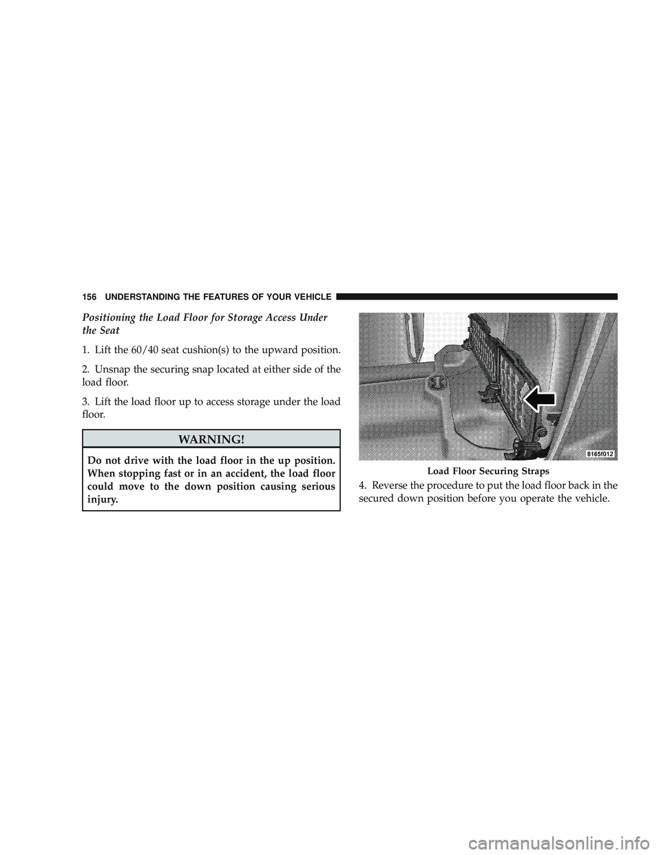
Positioning the Load Floor for Storage Access Under
the Seat
1. Lift the 60/40 seat cushion(s) to the upward position.
2. Unsnap the securing snap located at either side of the
load floor.
3. Lift the load floor up to access storage under the load
floor.
WARNING!
Do not drive with the load floor in the up position.
When stopping fast or in an accident, the load floor
could move to the down position causing serious
injury.4. Reverse the procedure to put the load floor back in the
secured down position before you operate the vehicle.Load Floor Securing Straps
156 UNDERSTANDING THE FEATURES OF YOUR VEHICLE
Page 167 of 429

The gauge pointer will likely indicate a higher tempera-
ture when driving in hot weather, up mountain grades,
or when towing a trailer. It should not be allowed to
exceed the upper limits of the normal operating range.
CAUTION!
Driving with a hot engine cooling system could
damage your vehicle. If temperature gauge reads “H”
pull over and stop the vehicle. Idle the vehicle with
the air conditioner turned off until the pointer drops
back into the normal range. If the pointer remains on
the “H” and you hear continuous chimes, turn the
engine off immediately, and call an authorized deal-
ership for service.
WARNING!
A hot engine cooling system is dangerous. You or
others could be badly burned by steam or boiling
coolant. You may want to call an authorized dealer-
ship for service if your vehicle overheats. If you
decide to look under the hood yourself, see Section 7
of this manual. Follow the warnings under the Cool-
ing System Pressure Cap paragraph.
14. Vehicle Security Light — If Equipped This light will flash at a fast rate for approxi-
mately 15 seconds, when the vehicle security
alarm is arming, and then will flash slowly
until the vehicle is disarmed.
UNDERSTANDING YOUR INSTRUMENT PANEL 165
4
Page 290 of 429

Tire Size
The tire size on the Label represents the actual tire size on
your vehicle. Replacement tires must be equal to the load
capacity of this tire size.
Rim Size
This is the rim size that is appropriate for the tire size
listed.
Inflation Pressure
This is the cold tire inflation pressure for your vehicle for
all loading conditions up to full GAWR.
Curb Weight
The curb weight of a vehicle is defined as the total weight
of the vehicle with all fluids, including vehicle fuel, at full
capacity conditions, and with no occupants or cargo
loaded into the vehicle. The front and rear curb weight
values are determined by weighing your vehicle on a
commercial scale before any occupants or cargo are
added.
Loading
The actual total weight and the weight of the front and
rear of your vehicle at the ground can best be determined
by weighing it when it is loaded and ready for operation.
The entire vehicle should first be weighed on a commer-
cial scale to insure that the GVWR has not been exceeded.
The weight on the front and rear of the vehicle should
then be determined separately to be sure that the load is
properly distributed over front and rear axle. Weighing
the vehicle may show that the GAWR of either the front
or rear axles has been exceeded but the total load is
within the specified GVWR. If so, weight must be shifted
from front to rear or rear to front as appropriate until the
specified weight limitations are met. Store the heavier
items down low and be sure that the weight is distributed
equally. Stow all loose items securely before driving.
288 STARTING AND OPERATING
Page 297 of 429

NOTE:Remember that everything put into or on the
trailer adds to the load on your vehicle. Also, additional
factory-installed options, or authorized dealer-installed
options must be considered as part of the total load on
your vehicle. Refer to “Tire and Loading Information
placard” under “Tire Safety Information” in Section 5.
Towing Requirements
To promote proper break-in of your new vehicle drive-
train components, the following guidelines are recom-
mended:
CAUTION!
•Avoid towing a trailer for the first 500 miles
(805 km) of vehicle operation. Doing so may dam-
age your vehicle.
•During the first 500 miles (805 km) of trailer
towing, limit your speed to 50 mph (80 km/h). Perform the maintenance listed in Section 8 of this
manual. When towing a trailer, never exceed the GAWR,
or GCWR, ratings.
WARNING!
Improper towing can lead to an injury accident.
Follow these guidelines to make your trailer towing
as safe as possible:
Make certain that the load is secured in the trailer
and will not shift during travel. When trailering
cargo that is not fully secured, dynamic load shifts
can occur that may be difficult for the driver to
control. You could lose control of your vehicle and
have an accident.
STARTING AND OPERATING 295
5
Page 320 of 429

WARNING! (Continued)
•If working on or near a roadway, be extremely
careful of motor traffic.
•To assure that spare tires, flat or inflated are
securely stowed, spares must be stowed with the
valve stem facing the ground.
•Turn on the Hazard Warning Flasher.1. If equipped, remove the spare wheel, jack, and tools
from storage.
2. Using the wheel wrench, loosen, but do not remove,
the wheel nuts by turning them counterclockwise one
turn while the wheel is still on the ground.
3. When changing the front wheel, assemble the jack
drive tube to the jack and connect the drive tube to the
extension tube. Place the jack under the axle as close to
the tire as possible with the drive tubes extending to the
front. Connect the jack tube extension and wheel wrench.
Jack Warning Label
318 WHAT TO DO IN EMERGENCIES
Page 321 of 429

When changing a rear wheel, assemble the jack drive
tube to the jack and connect the drive tube to the
extension tube. Securely place the jack under the sway
bar bracket (unless both tires are flat on one side, then
place jack under shock bracket) facing forward in vehicle.
Connect the jack tube extension and lug wrench.Before raising the wheel off the ground, make sure that
the jack will not damage surrounding truck parts and
adjust the jack position as required.
NOTE:
If the jack will not lower by turning the dial
(thumbwheel) by hand, it may be necessary to use the
jack drive tube in order to lower the jack.
Front Jacking LocationsRear Jacking Location
WHAT TO DO IN EMERGENCIES 319
6