clock RAM CHASSIS CAB 2011 User Guide
[x] Cancel search | Manufacturer: RAM, Model Year: 2011, Model line: CHASSIS CAB, Model: RAM CHASSIS CAB 2011Pages: 472, PDF Size: 7.38 MB
Page 244 of 472
INFO Button
Pressing the INFO button will cycle the display informa-
tion between Artist, Song Title, and Composer (if avail-
able). Also, pressing and holding the INFO button for an
additional three seconds will make the radio display the
Song Title all of the time (press and hold again to return
to normal display).
RW/FF
Pressing the RW (Rewind) or FF (Fast Forward) buttons
causes the tuner to search for the next channel in the
direction of the arrows.
TUNE Control (Rotary)
Turn the rotary TUNE/SCROLL control knob clockwise
to increase or counterclockwise to decrease the channel. MUSIC TYPE Button
Pressing this button once will turn on the Music Type
mode for five seconds. Pressing the MUSIC TYPE button
or turning the TUNE/SCROLL control knob within five
seconds will allow the program format type to be se-
lected.
Toggle the MUSIC TYPE button again to select the music
type.
By pressing the SEEK button when the Music Type
function is active, the radio will be tuned to the next
channel with the same selected Music Type name.
If a preset button is activated while in the Music Type
(Program Type) mode, the Music Type mode will be
exited and the radio will tune to the preset channel.
4 UNDERSTANDING YOUR INSTRUMENT PANEL 243
Page 249 of 472
Manual Heating and Air Conditioning System
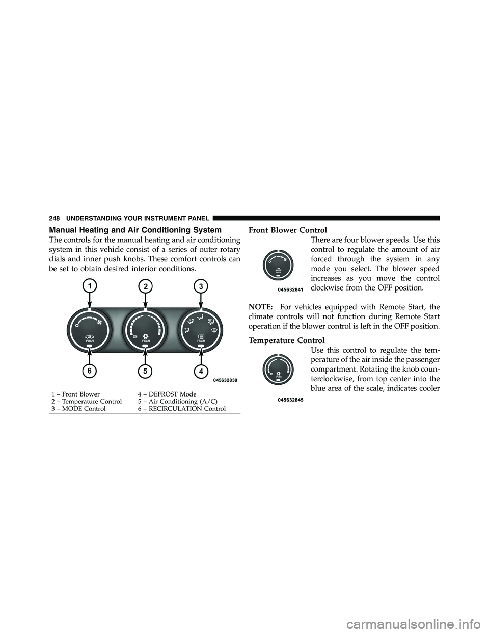
The controls for the manual heating and air conditioning
system in this vehicle consist of a series of outer rotary
dials and inner push knobs. These comfort controls can
be set to obtain desired interior conditions. Front Blower Control
There are four blower speeds. Use this
control to regulate the amount of air
forced through the system in any
mode you select. The blower speed
increases as you move the control
clockwise from the OFF position.
NOTE: For vehicles equipped with Remote Start, the
climate controls will not function during Remote Start
operation if the blower control is left in the OFF position.
Temperature Control
Use this control to regulate the tem-
perature of the air inside the passenger
compartment. Rotating the knob coun-
terclockwise, from top center into the
blue area of the scale, indicates cooler1 – Front Blower 4 – DEFROST Mode
2 – Temperature Control 5 – Air Conditioning (A/C)
3 – MODE Control 6 – RECIRCULATION Control248 UNDERSTANDING YOUR INSTRUMENT PANEL
Page 250 of 472
temperatures. Rotating the knob clockwise, into the red
area, indicates warmer temperatures.
NOTE: If your air conditioning performance seems
lower than expected, check the front of the A/C con-
denser (located in front of the radiator), for an accumu-
lation of dirt or insects. Clean with a gentle water spray
from behind the radiator and through the condenser.
Fabric front fascia protectors may reduce airflow to the
condenser, reducing air conditioning performance.
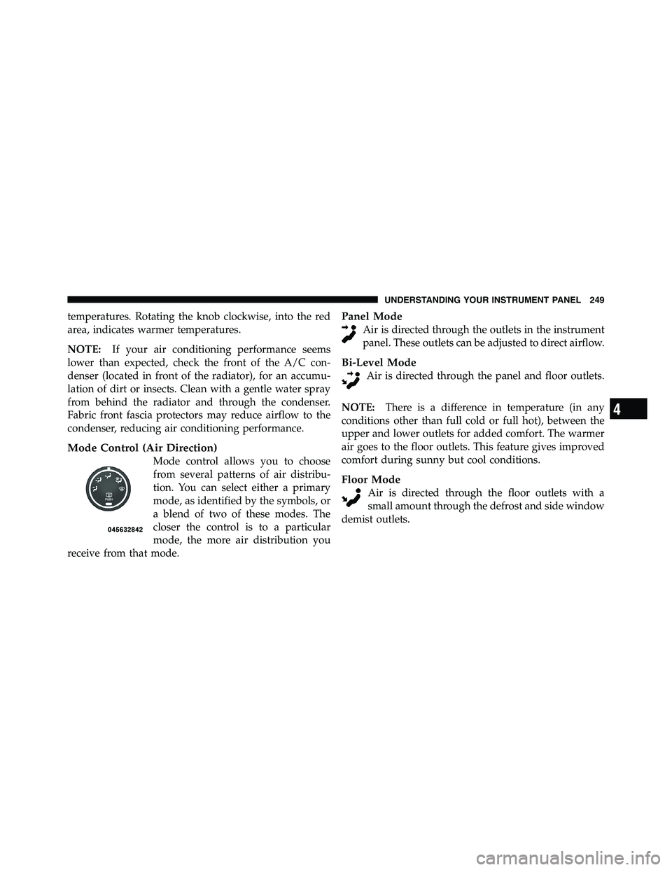
Mode Control (Air Direction)
Mode control allows you to choose
from several patterns of air distribu-
tion. You can select either a primary
mode, as identified by the symbols, or
a blend of two of these modes. The
closer the control is to a particular
mode, the more air distribution you
receive from that mode. Panel Mode
Air is directed through the outlets in the instrument
panel. These outlets can be adjusted to direct airflow.
Bi-Level Mode
Air is directed through the panel and floor outlets.
NOTE: There is a difference in temperature (in any
conditions other than full cold or full hot), between the
upper and lower outlets for added comfort. The warmer
air goes to the floor outlets. This feature gives improved
comfort during sunny but cool conditions.
Floor Mode
Air is directed through the floor outlets with a
small amount through the defrost and side window
demist outlets.
4 UNDERSTANDING YOUR INSTRUMENT PANEL 249
Page 255 of 472
NOTE:
• It is not necessary to move the temperature settings for
cold or hot vehicles. The system automatically adjusts
the temperature, mode and fan speed to provide
comfort as quickly as possible.
• The temperature can be displayed in U.S. or Metric
units by selecting the US/M customer-programmable
feature. Refer to the “Electronic Vehicle Information
Center (EVIC) — Customer-Programmable Features
(SETUP)” in this section of the manual.
To provide you with maximum comfort in the Automatic
mode, during cold start-ups the blower fan will remain
on low and the DELAY symbol will appear in the ATC
display until the engine warms up. The blower will
increase in speed and transition into Auto mode and
DELAY will no longer be illuminated in the display. The
blower will engage immediately if the Defrost mode is
selected, or by adjusting the blower control knob and
setting the fan to any fixed speed. Manual Operation
This system offers a full complement of manual override
features.
NOTE: Each of these features operate independently
from each other. If any one feature is controlled manually,
the temperature doors will continue to operate automati-
cally.
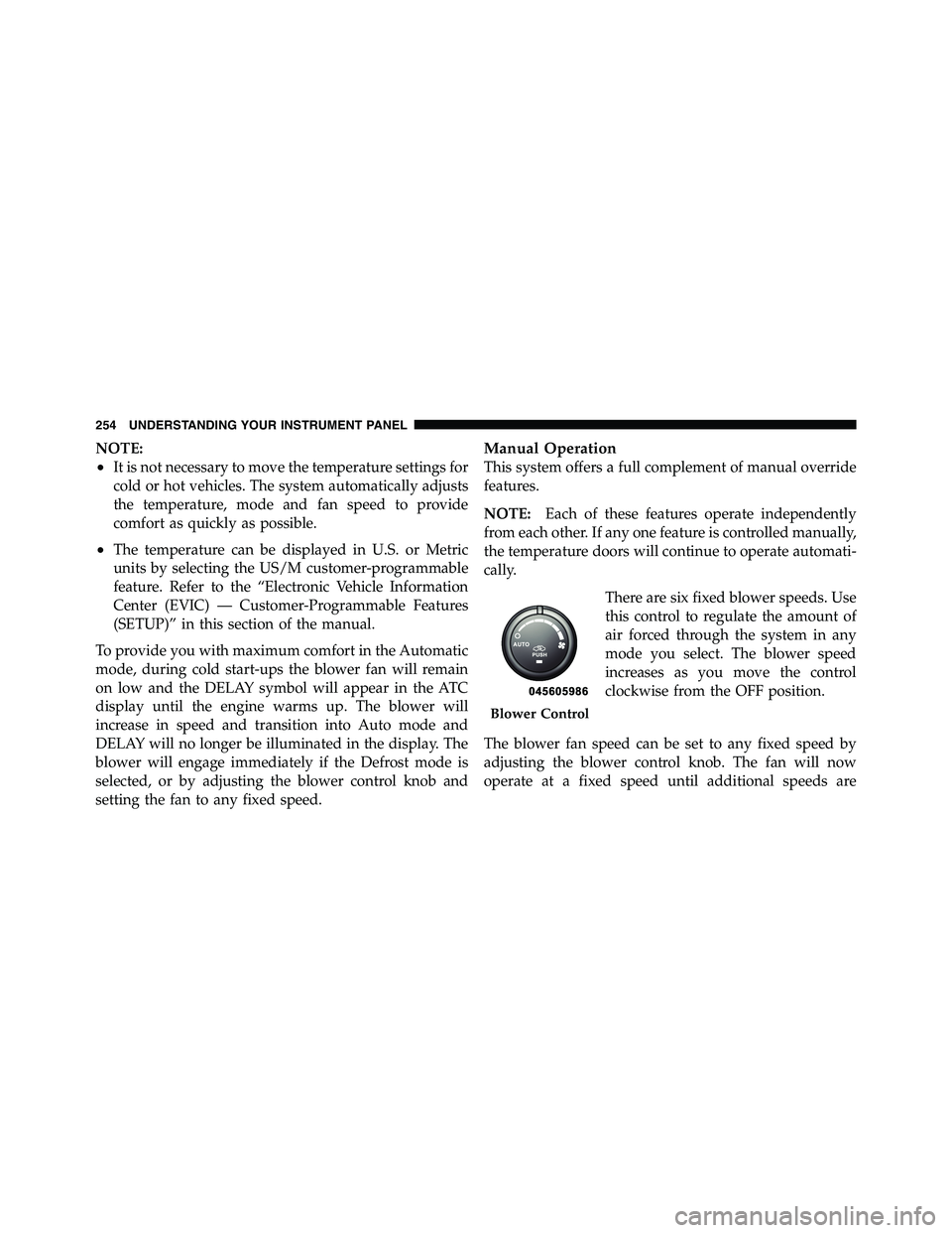
There are six fixed blower speeds. Use
this control to regulate the amount of
air forced through the system in any
mode you select. The blower speed
increases as you move the control
clockwise from the OFF position.
The blower fan speed can be set to any fixed speed by
adjusting the blower control knob. The fan will now
operate at a fixed speed until additional speeds are Blower Control254 UNDERSTANDING YOUR INSTRUMENT PANEL
Page 360 of 472
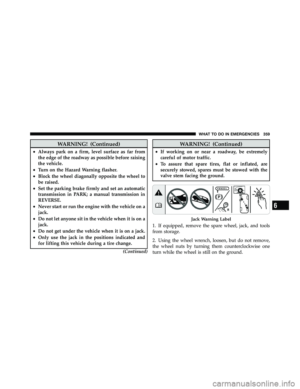
WARNING! (Continued)• Always park on a firm, level surface as far from
the edge of the roadway as possible before raising
the vehicle.
• Turn on the Hazard Warning flasher.
• Block the wheel diagonally opposite the wheel to
be raised.
• Set the parking brake firmly and set an automatic
transmission in PARK; a manual transmission in
REVERSE.
• Never start or run the engine with the vehicle on a
jack.
• Do not let anyone sit in the vehicle when it is on a
jack.
• Do not get under the vehicle when it is on a jack.
• Only use the jack in the positions indicated and
for lifting this vehicle during a tire change.
(Continued) WARNING! (Continued)• If working on or near a roadway, be extremely
careful of motor traffic.
• To assure that spare tires, flat or inflated, are
securely stowed, spares must be stowed with the
valve stem facing the ground.
1. If equipped, remove the spare wheel, jack, and tools
from storage.
2. Using the wheel wrench, loosen, but do not remove,
the wheel nuts by turning them counterclockwise one
turn while the wheel is still on the ground. Jack Warning Label
6 WHAT TO DO IN EMERGENCIES 359
Page 362 of 472

Before raising the wheel off the ground, make sure that
the jack will not damage surrounding truck parts and
adjust the jack position as required.
NOTE: If the jack will not lower by turning the dial
(thumbwheel) by hand, it may be necessary to use the
jack drive tube in order to lower the jack.
4. By rotating the wheel wrench clockwise, raise the
vehicle until the wheel just clears the surface.
WARNING!Raising the vehicle higher than necessary can make
the vehicle unstable and cause an accident. It could
slip off the jack and hurt someone near it. Raise the
vehicle only enough to remove the tire.
5. Remove the wheel nuts and pull the wheel off. Install
the spare wheel and wheel nuts with the cone shaped end
of the nuts toward the wheel on single rear wheel (SRW) models. On dual rear wheel models (DRW) the lug nuts
are a two-piece assembly with a flat face. Lightly tighten
the nuts. To avoid risk of forcing the vehicle off the jack,
do not fully tighten the nuts until the vehicle has been
lowered.
6. Using the wheel wrench, finish tightening the nuts
using a crisscross pattern. The correct nut tightness is
135 ft lbs (183 N·m) torque for single rear wheel (SRW)
models and 145 ft lbs (197 N·m) for dual rear wheel
models. If in doubt about the correct tightness, have them
checked with a torque wrench by your authorized dealer
or at a service station.
WARNING!A loose tire or jack thrown forward in an accident or
hard stop could injure someone in the vehicle. Al-
ways stow the jack parts and the extra tire and wheel
in the places provided.
6 WHAT TO DO IN EMERGENCIES 361
Page 419 of 472
10. Disconnect electrical connectors.
11. Replace bulb(s) as necessary.
CAUTION!• Do not contaminate the bulb glass by touching it
with your fingers or by allowing it to contact other
oily surfaces. Shortened bulb life will result.
• Always use the correct bulb size and type for
replacement. An incorrect bulb size or type may
overheat and cause damage to the lamp, the bulb
socket, or the lamp wiring.
NOTE: There are access covers over both headlamp
bulb access holes in the quad front lamp unit housing (if
equipped). These covers MUST be reinstalled after the
bulb has been replaced. Fog Lamps – If Equipped
1. Reach under and behind the front bumper to access
the back of the front fog lamp housing.
2. Disconnect the fog lamp wiring harness connector
from the fog lamp bulb.
3. Rotate the bulb counterclockwise 1
� 4
turn to unlock the
bulb from the housing.
4. Pull the bulb straight out from the housing.
CAUTION!Do not contaminate the bulb glass by touching it
with your fingers or by allowing it to contact other
oily surfaces. Shortened bulb life will result.418 MAINTAINING YOUR VEHICLE
Page 457 of 472
Carbon Monoxide Warning ............... 73,321
Cargo Light ............................ 144
Cellular Phone ........................ 88,247
Center High Mounted Stop Light ............ 419
Center Lap Belts ......................... 46
Center Seat Storage Compartment ............ 166
Certification Label ....................... 324
Chart, Tire Sizing ........................ 296
Check Engine Light
(Malfunction Indicator Light) ............. 189,379
Checking Your Vehicle For Safety ............. 72
Checks, Safety ........................... 72
Child Restraint ........................ 60,61
Child Restraint Tether Anchors ............. 64,67
Child Seat ............................ 61,65
Cigar Lighter ........................... 160
Cleaning
Wheels ............................. 407
Climate Control ......................... 247 Clock ............................. 212,221
Compact Disc (CD) Maintenance ............. 246
Compass .............................. 203
Compass Calibration ..................... 204
Compass Variance ....................... 204
Computer, Trip/Travel .................... 201
Connector
UCI ................................ 235
Universal Consumer Interface (UCI) ......... 235
Console, Overhead ....................... 155
Contract, Service ........................ 447
Coolant Pressure Cap (Radiator Cap) .......... 395
Cooling System ......................... 392
Adding Coolant (Antifreeze) .............. 394
Coolant Capacity ...................... 422
Coolant Level ...................... 393,396
Disposal of Used Coolant ................ 396
Drain, Flush, and Refill .................. 393
Inspection ........................... 396456 INDEX
Page 467 of 472
Safety Information, Tire ................... 294
Safety Tips ............................. 72
Satellite Radio Antenna ................. 232,241
Satellite Radio (Uconnect™ studios) ........... 240
Schedule, Maintenance .................... 426
Seat Belt Maintenance .................... 409
Seat Belt Reminder ....................... 48
Seat Belts .......................... 37,38,73
Adjustable Upper Shoulder Anchorage ........ 46
And Pregnant Women ................... 49
Child Restraint ....................... 60,71
Extender ............................. 49
Front Seat ............................ 38
Inspection ............................ 73
Reminder ............................ 191
Seats .............................. 123,134
Adjustment .......................... 123
Child ............................... 71
Heated ............................. 130 Memory ............................ 134
Power .............................. 127
Reclining ............................ 124
Security Alarm (Theft Alarm) ................ 18
Selection of Coolant (Antifreeze) .......... 393,423
Sentry Key (Immobilizer) ................... 16
Sentry Key Programming ................... 17
Sentry Key Replacement ................... 17
Service Assistance ....................... 445
Service Contract ......................... 447
Service Manuals ........................ 449
Setting the Clock ..................... 212,221
Settings, Personal ........................ 205
Shifting ............................... 266
Automatic Transmission ................. 268
Transfer Case ......................... 277
Transfer Case, Shifting into Transfer Case
Neutral (N) ....................... 346,349466 INDEX