start stop button RAM CHASSIS CAB 2020 User Guide
[x] Cancel search | Manufacturer: RAM, Model Year: 2020, Model line: CHASSIS CAB, Model: RAM CHASSIS CAB 2020Pages: 516, PDF Size: 16.57 MB
Page 191 of 516
STARTING AND OPERATING189
4. If the gear selector is in NEUTRAL, and the
vehicle speed below 5 mph (8 km/h),
pushing the ENGINE START/STOP button
once will turn the engine off. The ignition will
remain in the ACC mode.
5. If the vehicle speed is above 5 mph (8 km/ h), the ENGINE START/STOP button must be
held for two seconds (or three short pushes
in a row) to turn the engine off. The ignition
will remain in the ACC mode (NOT the OFF
mode) if the engine is turned off when the
transmission is not in PARK.
NOTE:
If the ignition is left in the ACC or ON/RUN
(engine not running) mode and the transmis -
sion is in PARK, the system will automatically
time out after 30 minutes of inactivity and the
ignition return to the OFF mode. ENGINE START/STOP Button Functions — With
Driver’s Foot OFF The Brake Pedal (In PARK Or
NEUTRAL Position)
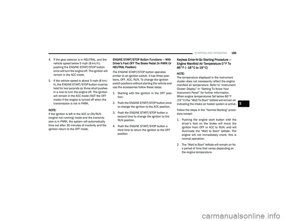
The ENGINE START/STOP button operates
similar to an ignition switch. It has three posi
-
tions, OFF, ACC, RUN. To change the ignition
switch positions without starting the vehicle and
use the accessories follow these steps:
1. Starting with the ignition in the OFF posi -
tion:
2. Push the ENGINE START/STOP button once to change the ignition to the ACC position.
3. Push the ENGINE START/STOP button a second time to change the ignition to the
RUN position.
4. Push the ENGINE START/STOP button a third time to return the ignition to the OFF
position.Keyless Enter-N-Go Starting Procedure —
Engine Manifold Air Temperature 0°F To
66°F (–18°C to 19°C)
NOTE:
The temperature displayed in the instrument
cluster does not necessarily reflect the engine
manifold air temperature. Refer to “Instrument
Cluster Display” in “Getting To Know Your
Instrument Panel” for further information.
When engine temperatures fall below 66°F
(19°C) the “Wait To Start” telltale will remain on
indicating the intake air heater system is active.
Follow the steps in the “Normal Starting” proce -
dure except:
1. Pushing the engine start button with the driver’s foot on the brake will move the
ignition from OFF or ACC to RUN, and will
illuminate the "Wait to Start" telltale. The
engine will not immediately crank, this is
normal operation.
2. The “Wait to Start" telltale will remain on for a period of time that varies depending on
the engine temperature.
5
2020_RAM_CHASSIS_CAB_OM_USA=GUID-6C67832B-7839-4CCF-BEFC-CDF988F949EA=1=en=.book Page 189
Page 194 of 516

192STARTING AND OPERATING
3. After the “Wait to Start” telltale goes off,
place the ignition switch in the START posi -
tion. Do not press the accelerator during
starting.
4. After engine start-up, check that the oil pressure warning light has turned off.
5. Release the parking brake and drive. NOTE:
Engine idle speed will automatically increase
to 1,000 RPM and engage the Variable
Geometry Turbocharger at low coolant
temperatures to improve engine warm-up.
Automatic equipped vehicles with optional
Keyless Enter-N-Go – If the ENGINE START/
STOP button is pushed once while in park
with the ignition off and driver’s foot on the
brake pedal, the vehicle will automatically
crank and start after the “Wait to Start” time
has elapsed. If it is desired to abort the start
process before it completes, the driver’s foot
should be fully removed from the brake pedal
prior to pushing the start button again in
order for the ignition to move directly to off.
If the engine stalls, or if the ignition switch is
left ON for more than two minutes after the
“Wait To Start” telltale goes out, reset the
intake air heater by turning the ignition
switch to the OFF position for at least five
seconds and then back ON. Repeat steps 1
through 5 of “Starting Procedure – Engine
Manifold Air Temperature Below 66°F
(19°C).”
Starting Procedure — Engine Manifold Air
Temperature Below 0°F (-18°C)
In extremely cold weather below 0°F (-18°C) it
may be beneficial to cycle the intake air heater
twice before attempting to start the engine. This
can be accomplished by turning the ignition OFF
for at least five seconds and then back ON after
the “Wait to Start” telltale has turned off, but
before the engine is started. However, exces
-
sive cycling of the intake air heater will result in
damage to the heater elements or reduced
battery voltage.
NOTE:
If multiple pre-heat cycles are used before
starting, additional engine run time may be
required to maintain battery state of charge at
a satisfactory level.
CAUTION!
If the “Water in Fuel Indicator Light” remains
on, DO NOT START the engine before you
drain the water from the fuel filters to avoid
engine damage. Refer to “Draining Fuel/
Water Separator Filter” in “Servicing And
Maintenance” for further information.
CAUTION!
Do not crank engine for more than 25
seconds at a time or starter motor damage
may result. Turn the ignition switch to the OFF
position and wait at least two minutes for the
starter to cool before repeating start
procedure.
2020_RAM_CHASSIS_CAB_OM_USA=GUID-6C67832B-7839-4CCF-BEFC-CDF988F949EA=1=en=.book Page 192
Page 205 of 516
STARTING AND OPERATING203
DIESEL EXHAUST BRAKE (ENGINE
BRAKING)
The purpose of the exhaust brake (engine
braking) feature is to supply negative (braking)
torque from the engine. Typically, the engine
braking is used for, but not limited to, vehicle
towing applications where vehicle braking can
be achieved by the internal engine power,
thereby sparing the mechanical brakes of the
vehicle.
Benefits of the exhaust brake are:
Vehicle driving control.
Reduced brake fade.
Longer brake life.
Faster cab warm-up.
The exhaust brake feature will only function
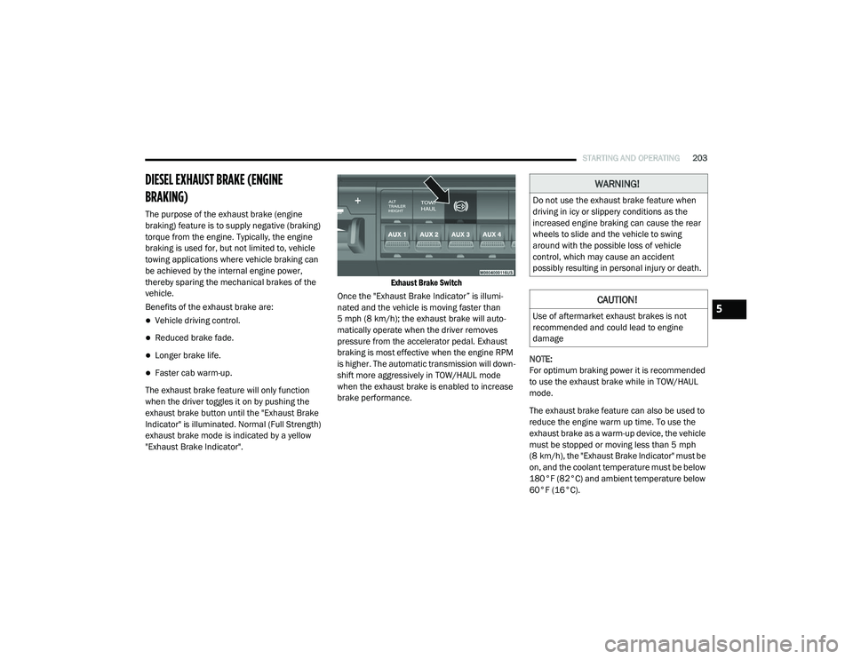
when the driver toggles it on by pushing the
exhaust brake button until the "Exhaust Brake
Indicator" is illuminated. Normal (Full Strength)
exhaust brake mode is indicated by a yellow
"Exhaust Brake Indicator".
Exhaust Brake Switch
Once the "Exhaust Brake Indicator” is illumi-
nated and the vehicle is moving faster than
5 mph (8 km/h); the exhaust brake will auto -
matically operate when the driver removes
pressure from the accelerator pedal. Exhaust
braking is most effective when the engine RPM
is higher. The automatic transmission will down -
shift more aggressively in TOW/HAUL mode
when the exhaust brake is enabled to increase
brake performance. NOTE:
For optimum braking power it is recommended
to use the exhaust brake while in TOW/HAUL
mode.
The exhaust brake feature can also be used to
reduce the engine warm up time. To use the
exhaust brake as a warm-up device, the vehicle
must be stopped or moving less than 5 mph
(8 km/h), the "Exhaust Brake Indicator" must be
on, and the coolant temperature must be below
180°F (82°C) and ambient temperature below
60°F (16°C).
WARNING!
Do not use the exhaust brake feature when
driving in icy or slippery conditions as the
increased engine braking can cause the rear
wheels to slide and the vehicle to swing
around with the possible loss of vehicle
control, which may cause an accident
possibly resulting in personal injury or death.
CAUTION!
Use of aftermarket exhaust brakes is not
recommended and could lead to engine
damage5
2020_RAM_CHASSIS_CAB_OM_USA=GUID-6C67832B-7839-4CCF-BEFC-CDF988F949EA=1=en=.book Page 203
Page 222 of 516

220STARTING AND OPERATING
This electronically shifted transfer case is
designed to be driven in the two–wheel drive
position (2WD) for normal street and highway
conditions on dry hard surfaced roads. Driving
the vehicle in 2WD will have greater fuel
economy benefits as the front axle is not
engaged in 2WD.
When additional traction is required, the
transfer case 4WD HIGH and 4WD LOW posi -
tions can be used to maximize torque to the
front driveshaft, forcing the front and rear
wheels to rotate at the same speed. This is
accomplished by pushing the desired position
on the 4WD control switch.
Refer to “Shifting Procedure” in this section for
specific shifting instructions.
The 4WD HIGH and 4WD LOW positions are
designed for loose, slippery road surfaces only.
Driving in the 4WD HIGH and 4WD LOW posi -
tions on dry hard surfaced roads may cause
increased tire wear and damage to the driveline
components. NOTE:
The transfer case Neutral button is located in
the center of the 4WD Control Switch and is
pushed by using a ballpoint pen or similar
object. The transfer case Neutral position is to
be used for recreational towing only. Refer to
“Recreational Towing” in “Starting And Oper
-
ating” for further information.
Transfer Case Position Indicator Lights
The Transfer Case Position Indicator Lights
(4WD HIGH and 4WD LOW) are located in the
instrument cluster and indicate the current and
desired transfer case selection. When you
select a different transfer case position, the
indicator lights will do the following:
If All Of The Following Shift Conditions Are Met:
1. The current position indicator light will turn off.
2. The selected position indicator light will flash until the transfer case completes the
shift.
3. When the shift is complete, the indicator light for the selected position will stop
flashing and remain on. If One Or More Of The Following Shift Conditions
Are Not Met:
1. The indicator light for the current position
will remain on.
2. The newly selected position indicator light will continue to flash.
3. The transfer case will not shift.
NOTE:
Before retrying a selection, make certain that all
the necessary requirements for selecting a new
transfer case position have been met. To retry
the selection, push the current position, wait
five seconds, and retry selection. To find the
shift requirements, refer to the “Shifting Proce-
dure” for your transfer case, located in this
section.
The “SVC 4WD Warning Light” monitors the
electronic shift four-wheel drive system. If this
light remains on after engine start up or illumi -
nates during driving, it means that the
four-wheel drive system is not functioning prop -
erly and that service is required.
2020_RAM_CHASSIS_CAB_OM_USA=GUID-6C67832B-7839-4CCF-BEFC-CDF988F949EA=1=en=.book Page 220
Page 234 of 516
232STARTING AND OPERATING
(Continued)
ADAPTIVE CRUISE CONTROL (ACC) — IF
EQUIPPED
Adaptive Cruise Control (ACC) increases the
driving convenience provided by cruise control
while traveling on highways and major road-
ways. However, it is not a safety system and not
designed to prevent collisions. Speed Control
function performs differently. Please refer to
the proper section within this chapter.
ACC will allow you to keep cruise control
engaged in light to moderate traffic conditions
without the constant need to reset your cruise
control. ACC utilizes a radar sensor and a
forward facing camera designed to detect a
vehicle directly ahead of you.
NOTE:
If the sensor does not detect a vehicle ahead
of you, ACC will maintain a fixed set speed.
If the ACC sensor detects a vehicle ahead,
ACC will apply limited braking or accelerate
(not to exceed the original set speed) auto -
matically to maintain a preset following
distance, while matching the speed of the
vehicle ahead. The Cruise Control system has two control
modes:
Adaptive Cruise Control mode for main
-
taining an appropriate distance between
vehicles.
Normal (Fixed Speed) Cruise Control mode
for cruising at a constant preset speed. For
additional information, refer to “Normal
(Fixed Speed) Cruise Control Mode” in this
section.
NOTE:
Normal (Fixed Speed) Cruise Control will not
react to preceding vehicles. Always be aware of
the mode selected.
You can change the mode by using the Cruise
Control buttons. The two control modes func -
tion differently. Always confirm which mode is
selected.
WARNING!
Adaptive Cruise Control (ACC) is a conve -
nience system. It is not a substitute for
active driving involvement. It is always the
driver’s responsibility to be attentive of
road, traffic, and weather conditions,
vehicle speed, distance to the vehicle
ahead; and, most importantly, brake opera -
tion to ensure safe operation of the vehicle
under all road conditions. Your complete
attention is always required while driving to
maintain safe control of your vehicle.
Failure to follow these warnings can result
in a collision and death or serious personal
injury.
The ACC system:
Does not react to pedestrians,
oncoming vehicles, and stationary
objects (e.g., a stopped vehicle in a
traffic jam or a disabled vehicle).
Cannot take street, traffic, and weather conditions into account, and may be
limited upon adverse sight distance
conditions.
2020_RAM_CHASSIS_CAB_OM_USA=GUID-6C67832B-7839-4CCF-BEFC-CDF988F949EA=1=en=.book Page 232
Page 235 of 516
STARTING AND OPERATING233
(Continued)
Adaptive Cruise Control (ACC) Operation
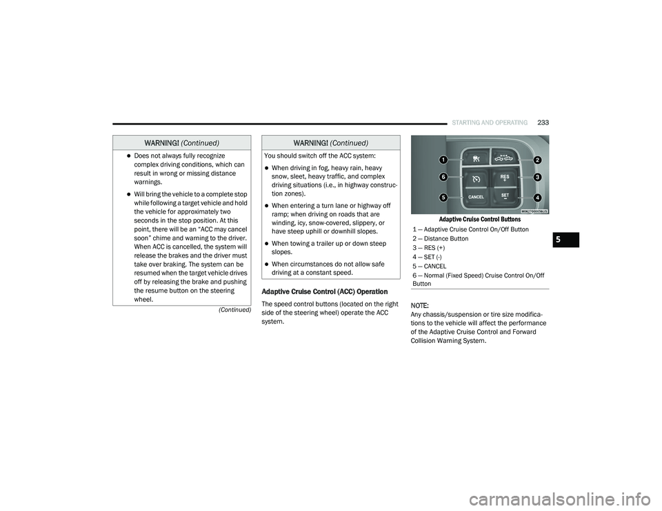
The speed control buttons (located on the right
side of the steering wheel) operate the ACC
system.
Adaptive Cruise Control Buttons
NOTE:
Any chassis/suspension or tire size modifica -
tions to the vehicle will affect the performance
of the Adaptive Cruise Control and Forward
Collision Warning System.
Does not always fully recognize complex driving conditions, which can
result in wrong or missing distance
warnings.
Will bring the vehicle to a complete stop while following a target vehicle and hold
the vehicle for approximately two
seconds in the stop position. At this
point, there will be an “ACC may cancel
soon” chime and warning to the driver.
When ACC is cancelled, the system will
release the brakes and the driver must
take over braking. The system can be
resumed when the target vehicle drives
off by releasing the brake and pushing
the resume button on the steering
wheel.
WARNING! (Continued)
You should switch off the ACC system:
When driving in fog, heavy rain, heavy
snow, sleet, heavy traffic, and complex
driving situations (i.e., in highway construc -
tion zones).
When entering a turn lane or highway off
ramp; when driving on roads that are
winding, icy, snow-covered, slippery, or
have steep uphill or downhill slopes.
When towing a trailer up or down steep
slopes.
When circumstances do not allow safe
driving at a constant speed.
WARNING! (Continued)
1 — Adaptive Cruise Control On/Off Button
2 — Distance Button
3 — RES (+)
4 — SET (-)
5 — CANCEL
6 — Normal (Fixed Speed) Cruise Control On/Off
Button
5
2020_RAM_CHASSIS_CAB_OM_USA=GUID-6C67832B-7839-4CCF-BEFC-CDF988F949EA=1=en=.book Page 233
Page 239 of 516

STARTING AND OPERATING237
Metric Speed (km/h)
Pushing the SET (-) button once will result in
a 1 km/h decrease in set speed. Each subse -
quent tap of the button results in a decrease
of 1 km/h.
If the button is continually pushed, the set
speed will continue to decrease in 10 km/h
decrements until the button is released. The
decrease in set speed is reflected in the
instrument cluster display.
NOTE:
When you override and push the RES (+)
button or SET (-) button, the new set speed
will be the current speed of the vehicle.
When you use the SET (-) button to decel -
erate, if the engine’s braking power does not
slow the vehicle sufficiently to reach the set
speed, the brake system will automatically
slow the vehicle.
The ACC system decelerates the vehicle to a
full stop when following a target vehicle. If an
ACC host vehicle follows a target vehicle to a
standstill, after two seconds the driver will either have to push the RES (+) button, or
apply the accelerator pedal to reengage the
ACC to the existing set speed.
The ACC system maintains set speed when
driving uphill and downhill. However, a slight
speed change on moderate hills is normal. In
addition, downshifting may occur while
climbing uphill or descending downhill. This
is normal operation and necessary to main
-
tain set speed. When driving uphill and down -
hill, the ACC system will cancel if the braking
temperature exceeds normal range (over -
heated).
Setting The Following Distance In ACC
The specified following distance for ACC can be
set by varying the distance setting between four
bars (longest), three bars (long), two bars
(medium) and one bar (short). Using this
distance setting and the vehicle speed, ACC
calculates and sets the distance to the vehicle
ahead. This distance setting displays in the
instrument cluster display.
Distance Setting 4 Bars (Longest)
Distance Setting 3 Bars (Long)
5
2020_RAM_CHASSIS_CAB_OM_USA=GUID-6C67832B-7839-4CCF-BEFC-CDF988F949EA=1=en=.book Page 237
Page 241 of 516

STARTING AND OPERATING239
Trailer Detect — If Equipped
When a trailer is detected, the ACC system auto -
matically defaults to the longest setting (four
bars). The setting can be overridden by pushing
the Distance Button on the steering wheel.
Overtake Aid
When driving with ACC engaged and following a
vehicle, the system will provide an additional
acceleration up to the ACC set speed to assist in
passing the vehicle. This additional acceleration
is triggered when the driver utilizes the left turn
signal and will only be active when passing on
the left hand side.
ACC Operation At Stop
In the event that the ACC system brings your
vehicle to a standstill while following a target
vehicle, if the target vehicle starts moving within
two seconds of your vehicle coming to a stand -
still, your vehicle will resume motion without the
need for any driver action. If the target vehicle does not start moving within
two seconds of your vehicle coming to a stand
-
still, then ACC will cancel and the driver must
take over braking. When the target vehicle
drives off, ACC can be resumed by releasing the
brake and pushing the RES (+) button.
NOTE:
After the ACC system holds your vehicle at a
standstill for approximately two seconds, a
chime will sound and an “ACC may cancel soon”
warning will display. The brakes will release
when ACC is cancelled and the driver must take
over braking.
While ACC is holding your vehicle at a
standstill, if the driver seatbelt is unbuckled or
the driver door is opened, the ACC system will
cancel and the brakes will release. Driver
intervention will be required at this moment.
Adaptive Cruise Control (ACC) Menu
The instrument cluster display will show the
current ACC system settings. The instrument
cluster display is located in the center of the
instrument cluster. The information it displays
depends on ACC system status.
Push the Adaptive Cruise Control (ACC) on/off
button (located on the steering wheel) until one
of the following appears in the instrument
cluster display:
Adaptive Cruise Control Off
When ACC is deactivated, the display will read
“Adaptive Cruise Control Off.”
Adaptive Cruise Control Ready
When ACC is activated, but the vehicle speed
setting has not been selected, the display will
read “Adaptive Cruise Control Ready.”
WARNING!
When the ACC system is resumed, the driver
must ensure that there are no pedestrians,
vehicles or objects in the path of the vehicle.
Failure to follow these warnings can result in
a collision and death or serious personal
injury.
5
2020_RAM_CHASSIS_CAB_OM_USA=GUID-6C67832B-7839-4CCF-BEFC-CDF988F949EA=1=en=.book Page 239
Page 268 of 516
266STARTING AND OPERATING
Trailer Reverse Guidance — If Equipped
The Trailer Reverse Guidance feature assists
the driver in backing up a trailer by providing
adjustable camera views of the trailer and
surrounding area. The cameras are mounted on
the side mirrors and the images will be
displayed side-by-side on the touchscreen. Left
and right camera images are swapped and
mirrored on the touchscreen to show the equiv -
alent area behind the vehicle as though the
driver is using the side mirrors.
Activation
The Trailer Reverse Guidance feature can be
activated by pressing the Trailer Reverse Guid -
ance button on the Backup/Cargo Camera
Display.
Deactivation
When the vehicle is shifted out of REVERSE
(with camera delay turned on), the camera
image will continue to be displayed for up to
10 seconds after shifting out of REVERSE
unless the vehicle speed exceeds 8 mph
(13 km/h), the vehicle is shifted into PARK or
the ignition is placed in the OFF position. There
is a touch screen button “X” to disable the
display of the camera image. If Trailer Reverse Guidance is selected through
manually activated Surround View, Backup
Camera, or Cargo Camera, the below deactiva
-
tion conditions are applied:
The “X” button on the display is pressed
The vehicle is shifted into PARK
The ignition is placed in the OFF position
The vehicle speed is over 8 mph (13 km/h)
for 10 seconds
NOTE:
If the vehicle is not equipped with a Pickup Box:
The bottom wedge of the Top view will be
displayed in black.
The Rear Cross Path soft button will be
greyed out.
The guide lines will not be overlaid on Top
view/Rear view and Full Screen of Backup
Camera view.
Black video will be displayed for the right side
of the Top and Rear view, and full screen of
the Backup Camera view when the Rear View
Camera is not connected.
WARNING!
Drivers must be careful when backing up
even when using the Surround View Camera.
Always check carefully behind your vehicle,
and be sure to check for pedestrians,
animals, other vehicles, obstructions, or blind
spots before backing up. You are responsible
for the safety of your surroundings and must
continue to pay attention while backing up.
Failure to do so can result in serious injury or
death.
CAUTION!
To avoid vehicle damage, Surround View
should only be used as a parking aid. The
Surround View camera is unable to view
every obstacle or object in your drive path.
To avoid vehicle damage, the vehicle must
be driven slowly when using Surround View
to be able to stop in time when an obstacle
is seen. It is recommended that the driver
look frequently over his/her shoulder when
using Surround View.
2020_RAM_CHASSIS_CAB_OM_USA=GUID-6C67832B-7839-4CCF-BEFC-CDF988F949EA=1=en=.book Page 266
Page 283 of 516

STARTING AND OPERATING281
An electronically actuated trailer brake
controller is required when towing a trailer
with electronically actuated brakes. When
towing a trailer equipped with a hydraulic
surge actuated brake system, an electronic
brake controller is not required.
Trailer brakes are recommended for trailers
over 1,000 lbs (453 kg) and required for
trailers in excess of 2,000 lbs (907 kg).
Integrated Trailer Brake Module — If
Equipped
Your vehicle may have an Integrated Trailer
Brake Module (ITBM) for Electric and Electric
Over Hydraulic (EOH) trailer brakes.
NOTE:
This module has been designed and verified
with electric trailer brakes and new EOH
systems. Some previous EOH systems may not
be compatible with ITBM.
Integrated Trailer Brake Module (ITBM)
The user interface consists of the following:
Manual Brake Control Lever
Slide the manual brake control lever to the left
to activate power to the trailer's electric brakes
independent of the tow vehicle's brakes. If the
manual brake control lever is activated while
the brake is also applied, the greater of the two
inputs determines the power sent to the trailer
brakes.WARNING!
Do not connect trailer brakes to your
vehicle's hydraulic brake lines. It can over -
load your brake system and cause it to fail.
You might not have brakes when you need
them and could have an accident.
Towing any trailer will increase your stop -
ping distance. When towing, you should
allow for additional space between your
vehicle and the vehicle in front of you.
Failure to do so could result in an accident.
CAUTION!
If the trailer weighs more than 1,000 lbs
(453 kg) loaded, it should have its own
brakes and they should be of adequate
capacity. Failure to do this could lead to
accelerated brake lining wear, higher brake
pedal effort, and longer stopping distances.
1 — GAIN Adjustment Button
2 — GAIN Adjustment Button
3 — Manual Brake Control Lever
5
2020_RAM_CHASSIS_CAB_OM_USA=GUID-6C67832B-7839-4CCF-BEFC-CDF988F949EA=1=en=.book Page 281