sensor RAM CHASSIS CAB 2020 Owners Manual
[x] Cancel search | Manufacturer: RAM, Model Year: 2020, Model line: CHASSIS CAB, Model: RAM CHASSIS CAB 2020Pages: 516, PDF Size: 16.57 MB
Page 7 of 516
5
FOUR-WHEEL DRIVE OPERATION —
IF EQUIPPED ...................................................... 218 Electronically Shifted Transfer Case (Eight
Speed Transmission) — If Equipped ........219 Electronically Shifted Transfer Case
(Six Speed Transmisson) —
If Equipped ...............................................222 Manually Shifted Transfer Case —
If Equipped .................................................226
LIMITED-SLIP DIFFERENTIAL .......................... 228
POWER TAKE OFF (PTO) OPERATION — IF
EQUIPPED .......................................................... 228
POWER STEERING ............................................. 229
Hydraulic Power Steering ..........................229
SPEED CONTROL .............................................. 230
To Activate .................................................. 230To Set A Desired Speed .............................230To Vary The Speed Setting ........................ 230To Accelerate For Passing ........................ 231To Resume Speed......................................231
To Deactivate .............................................231
ADAPTIVE CRUISE CONTROL (ACC) —
IF EQUIPPED .................................................... 232
Adaptive Cruise Control (ACC)
Operation ....................................................233 Activating Adaptive Cruise
Control (ACC) .............................................. 234 To Activate/Deactivate .............................. 234
To Set A Desired ACC Speed ..................... 235To Cancel.................................................... 235To Turn Off.................................................. 235
To Resume ................................................. 236
To Vary The Speed Setting ........................ 236
Setting The Following Distance In ACC..... 237Overtake Aid............................................... 239ACC Operation At Stop............................... 239Adaptive Cruise Control (ACC) Menu ........ 239Display Warnings And Maintenance ........ 240Precautions While Driving With ACC......... 241
General Information .................................. 244Normal (Fixed Speed) Cruise
Control Mode ............................................. 244
PARKSENSE REAR PARK ASSIST —
IF EQUIPPED .....................................................246
ParkSense Sensors ................................... 246
ParkSense Warning Display ...................... 247
ParkSense Display ..................................... 247
Enabling And Disabling ParkSense .......... 249Service The ParkSense Rear Park Assist
System ........................................................ 249 Cleaning The ParkSense System.............. 249
ParkSense System Usage Precautions .... 249 PARKSENSE FRONT AND REAR
PARK ASSIST ................................................... 250
ParkSense Sensors ................................... 251
ParkSense Warning Display...................... 251
ParkSense Display..................................... 251
Enabling And Disabling Front And/Or Rear
ParkSense .................................................. 254 Service The ParkSense Front/Rear Park
Assist System ............................................. 254 Cleaning The ParkSense System.............. 254
ParkSense System Usage Precautions .... 254
LANESENSE — IF EQUIPPED ........................... 256
LaneSense Operation................................ 256
Turning LaneSense On Or Off ................... 256
LaneSense Warning Message .................. 257Changing LaneSense Status..................... 258
PARKVIEW REAR BACK UP CAMERA ............ 258
AUX Camera — If Equipped ...................... 261
SURROUND VIEW CAMERA SYSTEM —
IF EQUIPPED ..................................................... 261
AUX Camera — If Equipped ...................... 267
ENGINE RUNAWAY ............................................ 267
REFUELING THE VEHICLE — GAS ENGINE ...... 268 Loose Fuel Filler Cap Message ................ 268
2020_RAM_CHASSIS_CAB_OM_USA=GUID-6C67832B-7839-4CCF-BEFC-CDF988F949EA=1=en=.book Page 5
Page 93 of 516

GETTING TO KNOW YOUR INSTRUMENT PANEL91
Diesel INSTRUMENT CLUSTER
1. Tachometer
Indicates the engine speed in revolutions
per minute (RPM x 1000).
2. Instrument Cluster Display
When the appropriate conditions exist, this display shows the instrument cluster
display messages. Refer to “Instrument
Cluster Display” in “Getting To Know Your
Instrument Panel” for further informa -
tion.
3. Speedometer
Indicates vehicle speed.
4. Fuel Gauge
The pointer shows the level of fuel in the fuel tank when the ignition switch is in
the ON/RUN position.
The fuel pump symbol points
to the side of the vehicle where
the fuel filler door is located. Refer to “Refueling The Vehicle — Diesel
Engine” in “Starting And Operating” for
further information.
5. Diesel Exhaust Fluid (DEF) Gauge
The DEF Gauge displays the actual level of Diesel Exhaust Fluid in the DEF tank.
Diesel Exhaust Fluid (DEF) is required to
maintain normal vehicle operation and
emissions compliance. If something is
wrong with the gauge, a DEF Warning
Message or Malfunction Indicator Light
(MIL) will be displayed. More information
is available in the instrument cluster
display section under the heading of
Diesel Exhaust Fluid (DEF) Warning
Messages. NOTE:
The DEF tank on these vehicles is designed
with a large amount of full reserve. So the
level sensor will indicate a full reading even
before the tank is completely full. To put it
another way, there’s additional storage
capacity in the tank above the Full mark
that’s not represented in the gauge. You may
not see any movement in the reading – even
after driving up to 200 miles
(321 kilometers) in some cases.
The gauge may take up to five seconds to
update after adding a gallon or more of
Diesel Exhaust Fluid (DEF) to the DEF tank. If
you have a fault related to the DEF system,
the gauge may not update to the new level.
See an authorized dealer for service.
The DEF gauge may also not immediately
update after a refill if the temperature of the
DEF fluid is below 39°F (4°C). The DEF tank
heater will possibly warm up the DEF fluid
and allow the gauge to update after a period
of run time. Under very cold conditions, it is
possible that the gauge may not reflect the
new fill level for several drives.
3
2020_RAM_CHASSIS_CAB_OM_USA=GUID-6C67832B-7839-4CCF-BEFC-CDF988F949EA=1=en=.book Page 91
Page 109 of 516
GETTING TO KNOW YOUR INSTRUMENT PANEL107
Battery Saver On/Battery Saver Mode
Message — Electrical Load Reduction
Actions — If Equipped
This vehicle is equipped with an Intelligent
Battery Sensor (IBS) to perform additional moni-
toring of the electrical system and status of the
vehicle battery.
In cases when the IBS detects charging system
failure, or the vehicle battery conditions are
deteriorating, electrical load reduction actions
will take place to extend the driving time and
distance of the vehicle. This is done by reducing
power to or turning off non-essential electrical
loads.
Load reduction is only active when the engine is
running. It will display a message if there is a
risk of battery depletion to the point where the
vehicle may stall due to lack of electrical supply,
or will not restart after the current drive cycle.
When load reduction is activated, the message
“Battery Saver On Some Systems May Have
Reduced Power” will appear in the instrument
cluster.
These messages indicate the vehicle battery
has a low state of charge and continues to lose
electrical charge at a rate that the charging
system cannot sustain. NOTE:
The charging system is independent from
load reduction. The charging system
performs a diagnostic on the charging
system continuously.
If the Battery Charge Warning Light is on it
may indicate a problem with the charging
system. Refer to “Battery Charge Warning
Light” in “Getting To Know Your Instrument
Panel” for further information.
The electrical loads that may be switched off (if
equipped), and vehicle functions which can be
affected by load reduction:
Heated Seats/Vented Seats/Heated Wheel
Rear Defroster And Heated Mirrors
HVAC System
115 Volt AC Power Inverter System
Audio and Telematics System Loss of the battery charge may indicate one or
more of the following conditions:
The charging system cannot deliver enough
electrical power to the vehicle system
because the electrical loads are larger than
the capability of charging system. The
charging system is still functioning properly.
Turning on all possible vehicle electrical
loads (e.g. HVAC to max settings, exterior and
interior lights, overloaded power outlets
+12 Volts, 115 Volt AC, USB ports) during
certain driving conditions (city driving,
towing, frequent stopping).
Installing options like additional lights,
upfitter electrical accessories, audio
systems, alarms and similar devices.
Unusual driving cycles (short trips separated
by long parking periods).
The vehicle was parked for an extended
period of time (weeks, months).
The battery was recently replaced and was
not charged completely.
3
2020_RAM_CHASSIS_CAB_OM_USA=GUID-6C67832B-7839-4CCF-BEFC-CDF988F949EA=1=en=.book Page 107
Page 116 of 516
114GETTING TO KNOW YOUR INSTRUMENT PANEL
Your vehicle has also been equipped with a
TPMS malfunction indicator to indicate when
the system is not operating properly. The TPMS
malfunction indicator is combined with the low
tire pressure telltale. When the system detects
a malfunction, the telltale will flash for approxi-
mately one minute and then remain continu -
ously illuminated. This sequence will continue
upon subsequent vehicle start-ups as long as
the malfunction exists. When the malfunction
indicator is illuminated, the system may not be
able to detect or signal low tire pressure as
intended. TPMS malfunctions may occur for a
variety of reasons, including the installation of
replacement or alternate tires or wheels on the
vehicle that prevent the TPMS from functioning
properly. Always check the TPMS malfunction
telltale after replacing one or more tires or
wheels on your vehicle to ensure that the
replacement or alternate tires and wheels allow
the TPMS to continue to function properly.
Anti-Lock Brake (ABS) Warning Light
This warning light monitors the
Anti-Lock Brake System (ABS). The
light will turn on when the ignition is
placed in the ON/RUN or ACC/ON/
RUN position and may stay on for as long as four
seconds.
If the ABS light remains on or turns on while
driving, then the Anti-Lock portion of the brake
system is not functioning and service is
required as soon as possible. However, the conventional brake system will continue to
operate normally, assuming the Brake Warning
Light is not also on.
If the ABS light does not turn on when the igni
-
tion is placed in the ON/RUN or ACC/ON/RUN
position, have the brake system inspected by an
authorized dealer.
Service Forward Collision Warning (FCW)
Light — If Equipped
This warning light will illuminate to
indicate a fault in the Forward Colli -
sion Warning System. Contact an
authorized dealer for service.
Refer to "Forward Collision Warning (FCW)" in
"Safety" for further information.
Service 4WD Warning Light — If Equipped
This warning light will illuminate to
signal a fault with the 4WD system. If
the light stays on or comes on during
driving, it means that the 4WD system
is not functioning properly and that service is
required. We recommend you drive to the
nearest service center and have the vehicle
serviced immediately.
CAUTION!
The TPMS has been optimized for the original
equipment tires and wheels. TPMS pressures
and warning have been established for the
tire size equipped on your vehicle.
Undesirable system operation or sensor
damage may result when using replacement
equipment that is not of the same size, type,
and/or style. Aftermarket wheels can cause
sensor damage. Using aftermarket tire
sealants may cause the Tire Pressure
Monitoring System (TPMS) sensor to become
inoperable. After using an aftermarket tire
sealant it is recommended that you take your
vehicle to an authorized dealer to have your
sensor function checked.
2020_RAM_CHASSIS_CAB_OM_USA=GUID-6C67832B-7839-4CCF-BEFC-CDF988F949EA=1=en=.book Page 114
Page 126 of 516

124SAFETY
(Continued)
Traction Control System (TCS)
The Traction Control System (TCS) monitors the
amount of wheel spin of each of the driven
wheels. If wheel spin is detected, the TCS may
apply brake pressure to the spinning wheel(s)
and/or reduce engine power to provide
enhanced acceleration and stability. A feature
of the TCS, Brake Limited Differential (BLD),
functions similar to a limited slip differential
and controls the wheel spin across a driven
axle. If one wheel on a driven axle is spinning
faster than the other, the system will apply the
brake of the spinning wheel. This will allow more
engine power to be applied to the wheel that is
not spinning. BLD may remain enabled even if
TCS and Electronic Stability Control (ESC) are in
a reduced mode.
Electronic Stability Control (ESC)
This system enhances directional control and
stability of the vehicle under various driving
conditions. ESC corrects for oversteering or
understeering of the vehicle by applying the
brake of the appropriate wheel(s) to assist in
counteracting the oversteer or understeer
condition. Engine power may also be reduced to
help the vehicle maintain the desired path.ESC uses sensors in the vehicle to determine
the vehicle path intended by the driver and
compares it to the actual path of the vehicle.
When the actual path does not match the
intended path, ESC applies the brake of the
appropriate wheel to assist in counteracting the
oversteer or understeer condition.
Oversteer — when the vehicle is turning
more than appropriate for the steering
wheel position.
Understeer — when the vehicle is turning
less than appropriate for the steering
wheel position.
The “ESC Activation/Malfunction Indicator
Light” located in the instrument cluster will start
to flash as soon as the ESC system becomes
active. The “ESC Activation/Malfunction Indi -
cator Light” also flashes when the TCS is active.
If the “ESC Activation/Malfunction Indicator
Light” begins to flash during acceleration, ease
up on the accelerator and apply as little throttle
as possible. Be sure to adapt your speed and
driving to the prevailing road conditions.
WARNING!
Electronic Stability Control (ESC) cannot
prevent the natural laws of physics from
acting on the vehicle, nor can it increase
the traction afforded by prevailing road
conditions. ESC cannot prevent accidents,
including those resulting from excessive
speed in turns, driving on very slippery
surfaces, or hydroplaning. ESC also cannot
prevent accidents resulting from loss of
vehicle control due to inappropriate driver
input for the conditions. Only a safe, atten -
tive, and skillful driver can prevent acci -
dents. The capabilities of an ESC equipped
vehicle must never be exploited in a reck -
less or dangerous manner which could
jeopardize the user’s safety or the safety of
others.
2020_RAM_CHASSIS_CAB_OM_USA=GUID-6C67832B-7839-4CCF-BEFC-CDF988F949EA=1=en=.book Page 124
Page 129 of 516

SAFETY127
NOTE:
The “ESC Activation/Malfunction Indicator
Light” and the “ESC OFF Indicator Light”
come on momentarily each time the ignition
is turned on.
Each time the ignition is turned on, the ESC
system will be on even if it was turned off
previously.
The ESC system will make buzzing or clicking
sounds when it is active. This is normal; the
sounds will stop when ESC becomes inactive
following the maneuver that caused the ESC
activation.
The “ESC Off Indicator Light” indi -
cates the customer has elected to
have the Electronic Stability Control
(ESC) in a reduced mode.
Electronic Roll Mitigation (ERM)
Electronic Roll Mitigation (ERM) anticipates the
potential for wheel lift by monitoring the driver’s
steering wheel input and the speed of the
vehicle. When ERM determines that the rate of
change of the steering wheel angle and
vehicle’s speed are sufficient to potentially
cause wheel lift, it then applies the appropriate brake and may also reduce engine power to
lessen the chance that wheel lift will occur. ERM
can only reduce the chance of wheel lift occur
-
ring during severe or evasive driving maneu -
vers; it cannot prevent wheel lift due to other
factors, such as road conditions, leaving the
roadway, or striking objects or other vehicles.
NOTE:
ERM is disabled anytime the ESC is in “Full Off”
mode (if equipped). Refer to “Electronic Stability
Control (ESC)” in this section for a complete
explanation of the available ESC modes.
Trailer Sway Control (TSC)
Trailer Sway Control (TSC) uses sensors in the
vehicle to recognize an excessively swaying
trailer and will take the appropriate actions to
attempt to stop the sway. TSC will become
active automatically once an excessively
swaying trailer is recognized.
NOTE:
TSC cannot stop all trailers from swaying.
Always use caution when towing a trailer and
follow the trailer tongue weight recommenda -
tions. Refer to “Trailer Towing” in “Starting And
Operating” for further information.
When TSC is functioning, the “ESC Activation/
Malfunction Indicator Light” will flash, the
engine power may be reduced and you may feel
the brakes being applied to individual wheels to
attempt to stop the trailer from swaying. TSC is
disabled when the ESC system is in the “Partial
Off” or “Full Off” modes.
WARNING!
Many factors, such as vehicle loading, road
conditions and driving conditions, influence
the chance that wheel lift or rollover may
occur. ERM cannot prevent all wheel lift or roll
overs, especially those that involve leaving
the roadway or striking objects or other
vehicles. The capabilities of an
ERM-equipped vehicle must never be
exploited in a reckless or dangerous manner
which could jeopardize the user's safety or
the safety of others.
WARNING!
If TSC activates while driving, slow the vehicle
down, stop at the nearest safe location, and
adjust the trailer load to eliminate trailer
sway.
4
2020_RAM_CHASSIS_CAB_OM_USA=GUID-6C67832B-7839-4CCF-BEFC-CDF988F949EA=1=en=.book Page 127
Page 131 of 516
SAFETY129
Disabling HDC
HDC will be deactivated and disabled if any of
the following conditions occur:
The driver pushes the HDC switch.
The driveline is shifted out of 4L Range.
The parking brake is applied.
The driver door opens.
The vehicle is driven greater than 20 mph
(32 km/h) for greater than 70 seconds.
The vehicle is driven greater than 40 mph
(64 km/h) (HDC exits immediately).
HDC detects excessive brake temperature.
Feedback To The Driver
The instrument cluster has an HDC icon and the
HDC switch has an LED icon, which offers feed -
back to the driver about the state HDC is in.
The cluster icon and switch lamp will illumi -
nate and remain on solid when HDC is
enabled or activated. This is the normal oper -
ating condition for HDC.
The cluster icon and switch lamp will flash for
several seconds then extinguish when the
driver pushes the HDC switch but enable
conditions are not met.
The cluster icon and switch lamp will flash for
several seconds then extinguish when HDC
disables due to excess speed.
The cluster icon and switch lamp will flash
when HDC deactivates due to overheated
brakes. The flashing will stop and HDC will
activate again once the brakes have cooled
sufficiently.
AUXILIARY DRIVING SYSTEMS
Forward Collision Warning (FCW) With
Mitigation — If Equipped
The Forward Collision Warning (FCW) system
with mitigation provides the driver with audible
warnings, visual warnings (within the instru -
ment cluster display), and may apply a brake
jerk to warn the driver when it detects a poten -
tial frontal collision. The warnings and limited
braking are intended to provide the driver with
enough time to react, avoid or mitigate the
potential collision.
NOTE:
FCW monitors the information from the forward
looking sensors as well as the Electronic Brake
Controller (EBC), to calculate the probability of a
forward collision. When the system determines
that a forward collision is probable, the driver
will be provided with audible and visual warn-
ings as well as a possible brake jerk warning.
WARNING!
HDC is only intended to assist the driver in
controlling vehicle speed when descending
hills. The driver must remain attentive to the
driving conditions and is responsible for
maintaining a safe vehicle speed.
4
2020_RAM_CHASSIS_CAB_OM_USA=GUID-6C67832B-7839-4CCF-BEFC-CDF988F949EA=1=en=.book Page 129
Page 135 of 516

SAFETY133
cold tire inflation pressure must not exceed the
maximum inflation pressure molded into the
tire sidewall. Refer to “Tires” in “Servicing And
Maintenance” for information on how to prop -
erly inflate the vehicle’s tires. The tire pressure
will also increase as the vehicle is driven - this is
normal and there should be no adjustment for
this increased pressure.
The TPMS will warn the driver of a low tire pres -
sure if the tire pressure falls below the low-pres -
sure warning limit for any reason, including low
temperature effects and natural pressure loss
through the tire.
The TPMS will continue to warn the driver of low
tire pressure as long as the condition exists,
and will not turn off until the tire pressure is at
or above the recommended cold placard pres -
sure. Once the low TPMS Warning Light illumi -
nates, you must increase the tire pressure to
the recommended cold placard pressure in
order for the TPMS Warning Light to turn off. The
system will automatically update and the TPMS
Warning Light will turn off once the system
receives the updated tire pressures. The vehicle
may need to be driven for up to 20 minutes
above 15 mph (24 km/h) in order for the TPMS to receive this information. NOTE:
When filling warm tires, the tire pressure may
need to be increased up to an additional 4 psi
(28 kPa) above the recommended cold placard
pressure in order to turn the TPMS Warning
Light off.
For example, your vehicle may have a recom
-
mended cold (parked for more than three
hours) placard pressure of 30 psi (207 kPa). If
the ambient temperature is 68°F (20°C) and
the measured tire pressure is 27 psi (186 kPa),
a temperature drop to 20°F (-7°C) will
decrease the tire pressure to approximately
23 psi (158 kPa). This tire pressure is suffi -
ciently low enough to turn on the TPMS Warning
Light. Driving the vehicle may cause the tire
pressure to rise to approximately 27 psi
(186 kPa), but the TPMS Warning Light will still
be on. In this situation, the TPMS Warning Light
will turn off only after the tires are inflated to the
vehicle’s recommended cold placard pressure
value.CAUTION!
The TPMS has been optimized for the orig -
inal equipment tires and wheels. TPMS
pressures and warning have been estab -
lished for the tire size equipped on your
vehicle. Undesirable system operation or
sensor damage may result when using
replacement equipment that is not of the
same size, type, and/or style. Aftermarket
wheels can cause sensor damage.
Using aftermarket tire sealants may cause
the Tire Pressure Monitoring System
(TPMS) sensor to become inoperable. After
using an aftermarket tire sealant it is
recommended that you take your vehicle to
an authorized dealership to have your
sensor function checked.
After inspecting or adjusting the tire pres -
sure always reinstall the valve stem cap.
This will prevent moisture and dirt from
entering the valve stem, which could
damage the TPMS sensor.
4
2020_RAM_CHASSIS_CAB_OM_USA=GUID-6C67832B-7839-4CCF-BEFC-CDF988F949EA=1=en=.book Page 133
Page 136 of 516
134SAFETY
NOTE:
The TPMS is not intended to replace normal
tire care and maintenance or to provide
warning of a tire failure or condition.
If your vehicle is not equipped with the Tire
Fill Alert feature the TPMS should not be used
as a tire pressure gauge while adjusting your
tire pressure.
Driving on a significantly under-inflated tire
causes the tire to overheat and can lead to
tire failure. Under-inflation also reduces fuel
efficiency and tire tread life, and may affect
the vehicle’s handling and stopping ability.
The TPMS is not a substitute for proper tire
maintenance, and it is the driver’s responsi -
bility to maintain correct tire pressure using
an accurate tire pressure gauge, even if
under-inflation has not reached the level to
trigger illumination of the TPMS Warning
Light.
Seasonal temperature changes will affect
tire pressure, and the TPMS will monitor the
actual tire pressure in the tire.
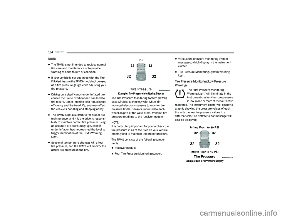
Example: Tire Pressure Monitoring Display
The Tire Pressure Monitoring System (TPMS)
uses wireless technology with wheel rim
mounted electronic sensors to monitor tire
pressure levels. Sensors, mounted to each
wheel as part of the valve stem, transmit tire
pressure readings to the receiver module.
NOTE:
It is particularly important for you to check the
tire pressure in all of the tires on your vehicle
monthly and to maintain the proper pressure.
The TPMS consists of the following compo -
nents:
Receiver module
Four Tire Pressure Monitoring sensors
Various tire pressure monitoring system
messages, which display in the instrument
cluster
Tire Pressure Monitoring System Warning
Light
Tire Pressure Monitoring Low Pressure
Warnings
The “Tire Pressure Monitoring
Warning Light” will illuminate in the
instrument cluster when tire pressure
is low in one or more of the four active
road tires. The instrument cluster will display a
graphic showing the pressure values of each
tire with the low tire pressure values in a
different color. An "Inflate to XX" message will
also be displayed.
Example: Low Tire Pressure Display
2020_RAM_CHASSIS_CAB_OM_USA=GUID-6C67832B-7839-4CCF-BEFC-CDF988F949EA=1=en=.book Page 134
Page 137 of 516

SAFETY135
Should this occur, you should stop as soon as
possible and inflate the tires with a low pressure
condition (those in a different color in the instru -
ment cluster graphic) to the vehicle’s recom-
mended cold placard pressure inflation value
as shown in the "Inflate to XX" message. Once
the system receives the updated tire pressures,
the system will automatically update, the
graphic display in the instrument cluster will
return to its original color, and the “Tire Pres -
sure Monitoring Warning Light” will turn off. The
vehicle may need to be driven for up to
20 minutes above 15 mph (24 km/h) in order
for the TPMS to receive this information.
NOTE:
When filling warm tires, the tire pressure may
need to be increased up to an additional 4 psi
(28 kPa) above the recommended cold placard
pressure in order to turn the Tire Pressure Moni -
toring Warning Light off.Service TPMS Warning
If a system fault is detected, the “Tire Pressure
Monitoring Warning Light” will flash on and off
for 75 seconds and then remain on solid. In
addition, the instrument cluster will display a
"SERVICE TPM SYSTEM" message for a
minimum of five seconds and then display
dashes (- -) in place of the pressure value to indi -
cate which sensor is not being received.
If the ignition switch is cycled, this sequence will
repeat, providing the system fault still exists. If
the system fault no longer exists, the “Tire Pres -
sure Monitoring Warning Light” will no longer
flash, and the "SERVICE TPM SYSTEM" message
will no longer display, and a pressure value will
display in place of the dashes. A system fault
can occur due to any of the following:
Signal interference due to electronic devices
or driving next to facilities emitting the same
radio frequencies as the TPM sensors.
Installing aftermarket window tinting that
contains materials that may block radio wave
signals.
Accumulation of snow or ice around the
wheels or wheel housings.
Using tire chains on the vehicle.
Using wheels/tires not equipped with TPM
sensors.
A system fault may occur due to an incorrect
TPM sensor location condition. When a system
fault occurs due to an incorrect TPM sensor
location, the “Tire Pressure MonitoringWarning
Light” will flash on and off for 75 seconds and
then remain on solid. The system fault will also
sound a chime. In addition, the instrument
cluster will display a “Tire Pressure Temporarily
Unavailable” message in place of the tire pres -
sure display screen. If the ignition switch is
cycled, this sequence will repeat, providing the
system fault still exists. If the system fault no
longer exists, the “Tire Pressure Monitoring Indi -
cator Light” will no longer flash and the tire pres -
sure display screen will be displayed showing
the tire pressure values in the correct locations.
4
2020_RAM_CHASSIS_CAB_OM_USA=GUID-6C67832B-7839-4CCF-BEFC-CDF988F949EA=1=en=.book Page 135