light RAM CHASSIS CAB 2022 Owners Manual
[x] Cancel search | Manufacturer: RAM, Model Year: 2022, Model line: CHASSIS CAB, Model: RAM CHASSIS CAB 2022Pages: 428, PDF Size: 20.18 MB
Page 360 of 428

358SERVICING AND MAINTENANCE
(Continued)
BRAKE SYSTEM
In order to ensure brake system performance, all
brake system components should be inspected
periodically Úpage 329.
Fluid Level Check — Brake Master Cylinder
The fluid level of the master cylinder should be
checked when performing under the hood service
or immediately if the Brake System Warning Light
indicates system failure.
If necessary, add fluid to bring level within the
designated marks on the side of the reservoir of
the brake master cylinder. Be sure to clean the top
of the master cylinder area before removing cap.
With disc brakes the fluid level can be expected to
fall as the brake linings wear. However, an
unexpected drop in fluid level may be caused by a
leak and a system check should be conducted.
For further information Ú page 407.
AUTOMATIC TRANSMISSION
Special Additives
The manufacturer strongly recommends against
using any special additives in the transmission.
Automatic Transmission Fluid (ATF) is an
engineered product and its performance may be
impaired by supplemental additives. Therefore, do
not add any fluid additives to the transmission. The
only exception to this policy is the use of special
dyes for diagnosing fluid leaks in 6-speed
transmissions. Avoid using transmission sealers as
they may adversely affect seals.
WARNING!
Riding the brakes can lead to brake failure and
possibly a collision. Driving with your foot resting
or riding on the brake pedal can result in
abnormally high brake temperatures, excessive
lining wear, and possible brake damage. You
would not have your full braking capacity in an
emergency.
WARNING!
Use only manufacturer's recommended brake
fluid Úpage 407. Using the wrong type of
brake fluid can severely damage your brake
system and/or impair its performance. The
proper type of brake fluid for your vehicle is
also identified on the original factory installed
hydraulic master cylinder reservoir.
To avoid contamination from foreign matter or
moisture, use only new brake fluid or fluid that
has been in a tightly closed container. Keep
the master cylinder reservoir cap secured at
all times. Brake fluid in an open container
absorbs moisture from the air resulting in a
lower boiling point. This may cause it to boil
unexpectedly during hard or prolonged
braking, resulting in sudden brake failure. This
could result in a collision.
Overfilling the brake fluid reservoir can result
in spilling brake fluid on hot engine parts,
causing the brake fluid to catch fire. Brake
fluid can also damage painted and vinyl
surfaces, care should be taken to avoid its
contact with these surfaces.
Do not allow petroleum based fluid to contam -
inate the brake fluid. Brake seal components
could be damaged, causing partial or
complete brake failure. This could result in a
collision.
CAUTION!
Do not use chemical flushes in your
transmission as the chemicals can damage your
transmission components. Such damage is not
covered by the New Vehicle Limited Warranty.
WARNING!
22_DPF_OM_EN_USC_t.book Page 358
Page 363 of 428

SERVICING AND MAINTENANCE361
Drain And Refill
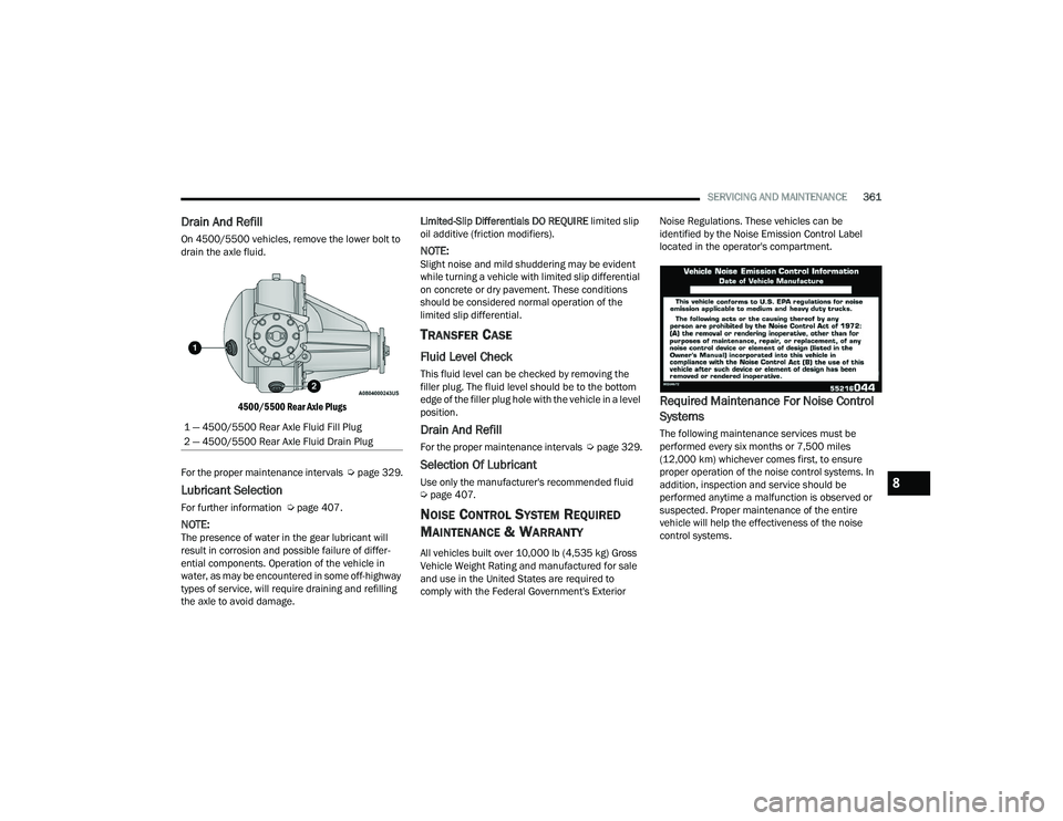
On 4500/5500 vehicles, remove the lower bolt to
drain the axle fluid.
4500/5500 Rear Axle Plugs
For the proper maintenance intervals Úpage 329.
Lubricant Selection
For further information Ú page 407.
NOTE:The presence of water in the gear lubricant will
result in corrosion and possible failure of differ -
ential components. Operation of the vehicle in
water, as may be encountered in some off-highway
types of service, will require draining and refilling
the axle to avoid damage. Limited-Slip Differentials DO REQUIRE
limited slip
oil additive (friction modifiers).
NOTE:Slight noise and mild shuddering may be evident
while turning a vehicle with limited slip differential
on concrete or dry pavement. These conditions
should be considered normal operation of the
limited slip differential.
TRANSFER CASE
Fluid Level Check
This fluid level can be checked by removing the
filler plug. The fluid level should be to the bottom
edge of the filler plug hole with the vehicle in a level
position.
Drain And Refill
For the proper maintenance intervals Úpage 329.
Selection Of Lubricant
Use only the manufacturer's recommended fluid
Úpage 407.
NOISE CONTROL SYSTEM REQUIRED
M
AINTENANCE & WARRANTY
All vehicles built over 10,000 lb (4,535 kg) Gross
Vehicle Weight Rating and manufactured for sale
and use in the United States are required to
comply with the Federal Government's Exterior Noise Regulations. These vehicles can be
identified by the Noise Emission Control Label
located in the operator's compartment.
Required Maintenance For Noise Control
Systems
The following maintenance services must be
performed every six months or 7,500 miles
(12,000 km) whichever comes first, to ensure
proper operation of the noise control systems. In
addition, inspection and service should be
performed anytime a malfunction is observed or
suspected. Proper maintenance of the entire
vehicle will help the effectiveness of the noise
control systems.
1 — 4500/5500 Rear Axle Fluid Fill Plug
2 — 4500/5500 Rear Axle Fluid Drain Plug
8
22_DPF_OM_EN_USC_t.book Page 361
Page 368 of 428

366SERVICING AND MAINTENANCE
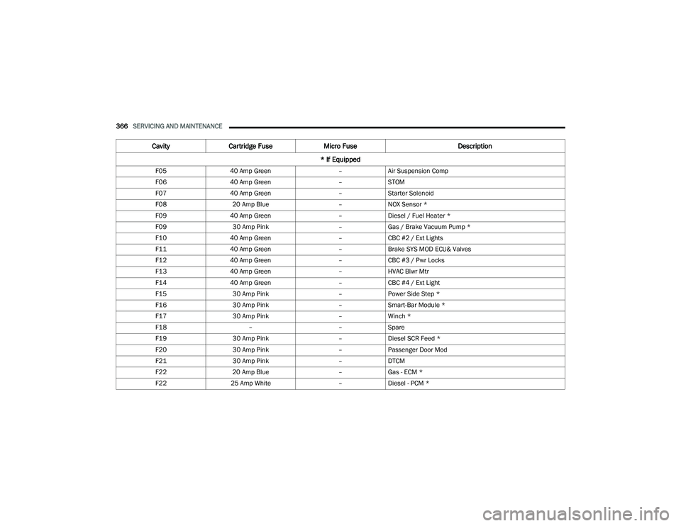
F05 40 Amp Green –Air Suspension Comp
F06 40 Amp Green –STOM
F07 40 Amp Green –Starter Solenoid
F08 20 Amp Blue –NOX Sensor *
F09 40 Amp Green –Diesel / Fuel Heater *
F09 30 Amp Pink –Gas / Brake Vacuum Pump *
F10 40 Amp Green –CBC #2 / Ext Lights
F11 40 Amp Green –Brake SYS MOD ECU& Valves
F12 40 Amp Green –CBC #3 / Pwr Locks
F13 40 Amp Green –HVAC Blwr Mtr
F14 40 Amp Green –CBC #4 / Ext Light
F15 30 Amp Pink –Power Side Step *
F16 30 Amp Pink –Smart-Bar Module *
F17 30 Amp Pink –Winch *
F18 ––Spare
F19 30 Amp Pink –Diesel SCR Feed *
F20 30 Amp Pink –Passenger Door Mod
F21 30 Amp Pink –DTCM
F22 20 Amp Blue –Gas - ECM *
F22 25 Amp White –Diesel - PCM *
Cavity Cartridge Fuse Micro Fuse Description
* If Equipped
22_DPF_OM_EN_USC_t.book Page 366
Page 369 of 428

SERVICING AND MAINTENANCE367
F23 30 Amp Pink –CBC #1 / Int Light
F24 30 Amp Pink –Driver Door Mod
F25 30 Amp Pink –FT Wiper
F26 ––Spare
F27 ––Spare
F28 20 Amp Blue –TRLR Tow B/U
F29 20 Amp Blue –TRLR TOW PARK
F30 30 Amp Pink –TRLR Tow
F31 ––Spare
F32 ––Spare
F33 20 Amp Blue –Trans Control Mod *
F34 30 Amp Pink –VSIM #2 *
F35 30 Amp Pink –Sunroof *
F36 30 Amp Pink –Rear Defroster (EBL) *
F37 30 Amp Pink –Diesel Frame / Fuel HTR *
F38 30 Amp Pink –ITBM *
F39 ––Spare
F40 –10 Amp Red Vented Seats *
F41 –10 Amp Red Act Grille Shutter / Dam *
F42 –20 Amp Yellow Horn
Cavity Cartridge Fuse Micro Fuse Description
* If Equipped
8
22_DPF_OM_EN_USC_t.book Page 367
Page 370 of 428

368SERVICING AND MAINTENANCE
F43 –15 Amp Blue Heated Strng Wheel *
F44 –10 Amp Red Diagnostic Port
F45 ––Spare
F46 –10 Amp Red Upfitters Relay Coils *
F47 ––Spare
F48 ––Spare
F49 –10 Amp Red IP Cluster / CSG
F50 –20 Amp Yellow Air Suspension Mod *
F51 –10 Amp Red IGN Mod / KIN Mod/ RF Hub
F52 –5 Amp Tan Batt Snsr
F53 –20 Amp Yellow Trlr Tow – Lt Turn/Stop
F54 –20 Amp Yellow Non-Memory Adjustable Pedals *
F55 ––Spare
F56 –10 Amp Red Fuel Vapor Blocking Valve (VBV) *
F57 –20 Amp Yellow TCM / PCM / Trans PRSR SW
F58 –10 Amp Red Bed Lighting
F59 ––Spare
F60 ––Spare
F61 –10 Amp Red NH3 Sensor / PM Sensor *
F62 –10 Amp Red A/C Clutch
CavityCartridge Fuse Micro Fuse Description
* If Equipped
22_DPF_OM_EN_USC_t.book Page 368
Page 373 of 428

SERVICING AND MAINTENANCE371
BULB REPLACEMENT
Replacement Bulbs, Names, And Part Numbers
In the instance a bulb needs to be replaced, this section includes bulb description and replacement part numbers.
NOTE:See an authorized dealer for LED bulb replacement.F101
–20 Amp Yellow RR HTD ST Right *
F102 –20 Amp Yellow RR HTD ST Left / Run RLY #3 *
F103 –10 Amp Red HeadLamp AFLS *
F104 –20 Amp Yellow UCI Port / USB Rear
Cavity Cartridge Fuse Micro Fuse Description
* If Equipped
Interior Bulbs
Bulb Name Bulb Number
Overhead Console Lamps TS 212–9
Dome Lamp 7679
NOTE:For lighted switches, see an authorized dealer for replacement instructions.
8
22_DPF_OM_EN_USC_t.book Page 371
Page 378 of 428

376SERVICING AND MAINTENANCE
2. Rotate the bulb socket a quarter turn and pull it from the lamp assembly.
Removing Bulb Socket From Clearance Lamp
3. Pull the bulb straight from it's socket and replace.
TIRES
TIRE SAFETY INFORMATION
Tire safety information will cover aspects of the
following information: Tire Markings, Tire
Identification Numbers, Tire Terminology and
Definitions, Tire Pressures, and Tire Loading.
Tire Markings
Tire Markings
NOTE:
P (Passenger) — Metric tire sizing is based on US
design standards. P-Metric tires have the letter
“P” molded into the sidewall preceding the size
designation. Example: P215/65R15 95H.
European — Metric tire sizing is based on Euro -
pean design standards. Tires designed to this
standard have the tire size molded into the side -
wall beginning with the section width. The letter
"P" is absent from this tire size designation.
Example: 215/65R15 96H.
LT (Light Truck) — Metric tire sizing is based on
US design standards. The size designation for
LT-Metric tires is the same as for P-Metric tires
except for the letters “LT” that are molded into
the sidewall preceding the size designation.
Example: LT235/85R16.
Temporary spare tires are designed for tempo -
rary emergency use only. Temporary high pres -
sure compact spare tires have the letter “T” or
“S” molded into the sidewall preceding the size
designation. Example: T145/80D18 103M.
High flotation tire sizing is based on US design
standards and it begins with the tire diameter
molded into the sidewall. Example: 31x10.5
R15 LT.
1 — US DOT Safety Standards Code (TIN)
2 — Size Designation
3 — Service Description
4 — Maximum Load
5 — Maximum Pressure
6 — Treadwear, Traction and
Temperature Grades
22_DPF_OM_EN_USC_t.book Page 376
Page 379 of 428

SERVICING AND MAINTENANCE377
TIRE SIZING CHART
EXAMPLE:
Example Size Designation: P215/65R15XL 95H, 215/65R15 96H, LT235/85R16C, T145/80D18 103M, 31x10.5 R15 LT
P = Passenger car tire size based on US design standards, or
"....blank...." = Passenger car tire based on European design standards, or
LT = Light truck tire based on US design standards, or
T or S = Temporary spare tire or
31 = Overall diameter in inches (in)
215, 235, 145 = Section width in millimeters (mm)
65, 85, 80 = Aspect ratio in percent (%)
Ratio of section height to section width of tire, or
10.5 = Section width in inches (in)
R = Construction code
"R" means radial construction, or
"D" means diagonal or bias construction
15, 16, 18 = Rim diameter in inches (in)
Service Description:
95 = Load Index
A numerical code associated with the maximum load a tire can carry
H = Speed Symbol
A symbol indicating the range of speeds at which a tire can carry a load corresponding to its load index under certain operating conditions
The maximum speed corresponding to the speed symbol should only be achieved under specified operating conditions (i.e., tire pressure, vehicle loading,
road conditions, and posted speed limits)
8
22_DPF_OM_EN_USC_t.book Page 377
Page 380 of 428

378SERVICING AND MAINTENANCE
Tire Identification Number (TIN)
The TIN may be found on one or both sides of the tire; however, the date code may only be on one side. Tires with white sidewalls will have the full TIN, including
the date code, located on the white sidewall side of the tire. Look for the TIN on the outboard side of black sidewall tires as mounted on the vehicle. If the TIN is
not found on the outboard side, then you will find it on the inboard side of the tire.Load Identification:
Absence of the following load identification symbols on the sidewall of the tire indicates a Standard Load (SL) tire:
XL = Extra load (or reinforced) tire, or
LL
= Light load tire or
C, D, E, F, G = Load range associated with the maximum load a tire can carry at a specified pressure
Maximum Load – Maximum load indicates the maximum load this tire is designed to carry
Maximum Pressure – Maximum pressure indicates the maximum permissible cold tire inflation pressure for this tire
EXAMPLE:
EXAMPLE:
DOT MA L9 ABCD 0301
DOT = Department of Transportation
This symbol certifies that the tire is in compliance with the US Department of Transportation tire safety standards and is approved for highway use
MA = Code representing the tire manufacturing location (two digits)
L9 = Code representing the tire size (two digits)
ABCD = Code used by the tire manufacturer (one to four digits)
03 = Number representing the week in which the tire was manufactured (two digits)
03 means the 3rd week
22_DPF_OM_EN_USC_t.book Page 378
Page 388 of 428

386SERVICING AND MAINTENANCE
Keep dismounted tires in a cool, dry place with as
little exposure to light as possible. Protect tires
from contact with oil, grease, and gasoline.
Replacement Tires
The tires on your new vehicle provide a balance of
many characteristics. They should be inspected
regularly for wear and correct cold tire inflation
pressures. The manufacturer strongly
recommends that you use tires equivalent to the
originals in size, quality and performance when
replacement is needed Ú page 385. Refer to the
Tire and Loading Information placard or the
Vehicle Certification Label for the size designation
of your tire. The Load Index and Speed Symbol for
your tire will be found on the original equipment
tire sidewall.
For more information relating to the Load Index
and Speed Symbol of a tire Ú page 376.
It is recommended to replace the two front tires or
two rear tires as a pair. Replacing just one tire can
seriously affect your vehicle’s handling. If you ever
replace a wheel, make sure that the wheel’s
specifications match those of the original wheels.
It is recommended you contact an authorized tire
dealer or original equipment dealer with any
questions you may have on tire specifications or
capability. Failure to use equivalent replacement
tires may adversely affect the safety, handling, and
ride of your vehicle.
TIRE TYPES
All Season Tires — If Equipped
All Season tires provide traction for all seasons
(Spring, Summer, Autumn, and Winter). Traction
levels may vary between different all season tires.
All season tires can be identified by the M+S, M&S,
M/S or MS designation on the tire sidewall. Use all
season tires only in sets of four; failure to do so
may adversely affect the safety and handling of
your vehicle.
Summer Or Three Season Tires —
If Equipped
Summer tires provide traction in both wet and dry
conditions, and are not intended to be driven in
snow or on ice. If your vehicle is equipped with
Summer tires, be aware these tires are not
designed for Winter or cold driving conditions.
Install Winter tires on your vehicle when ambient
temperatures are less than 40°F (5°C) or if roads
are covered with ice or snow. For more
information, contact an authorized dealer.
WARNING!
Do not use a tire, wheel size, load rating, or
speed rating other than that specified for your
vehicle. Some combinations of unapproved
tires and wheels may change suspension
dimensions and performance characteristics,
resulting in changes to steering, handling, and
braking of your vehicle. This can cause unpre -
dictable handling and stress to steering and
suspension components. You could lose
control and have a collision resulting in
serious injury or death. Use only the tire and
wheel sizes with load ratings approved for
your vehicle.
Never use a tire with a smaller load index or
capacity, other than what was originally
equipped on your vehicle. Using a tire with a
smaller load index could result in tire over -
loading and failure. You could lose control and
have a collision.
Failure to equip your vehicle with tires having
adequate speed capability can result in
sudden tire failure and loss of vehicle control.
CAUTION!
Replacing original tires with tires of a different
size may result in false speedometer and
odometer readings.
22_DPF_OM_EN_USC_t.book Page 386