maintenance RAM CHASSIS CAB 2022 Owners Manual
[x] Cancel search | Manufacturer: RAM, Model Year: 2022, Model line: CHASSIS CAB, Model: RAM CHASSIS CAB 2022Pages: 428, PDF Size: 20.18 MB
Page 3 of 428
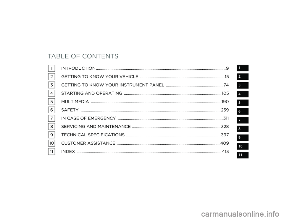
TABLE OF CONTENTS
1
2
3
4
5
6
7
8
9
10
11
1 INTRODUCTION .............................................................................................................................. 9
2 GETTING TO KNOW YOUR VEHICLE ..................................................................................15
3 GETTING TO KNOW YOUR INSTRUMENT PANEL ....................................................... 74
4 STARTING AND OPERATING ...............................................................................................105 5 MULTIMEDIA ...............................................................................................................................190
6 SAFETY ........................................................................................................................................ 259 7 IN CASE OF EMERGENCY ...................................................................................................... 311
8 SERVICING AND MAINTENANCE ...................................................................................... 328
9 TECHNICAL SPECIFICATIONS ............................................................................................ 397
10 CUSTOMER ASSISTANCE .................................................................................................... 409 11 INDEX .............................................................................................................................................. 413
22_DPF_OM_EN_USC_t.book Page 1
Page 6 of 428
4
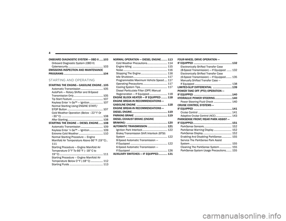
ONBOARD DIAGNOSTIC SYSTEM — OBD II ...... 103 Onboard Diagnostic System (OBD II)
Cybersecurity ................................................. 103
EMISSIONS INSPECTION AND MAINTENANCE
PROGRAMS .......................................................... 104
STARTING AND OPERATING
STARTING THE ENGINE— GASOLINE ENGINE .. 105
Automatic Transmission ............................... 105
AutoPark — Rotary Shifter and 8-Speed
Transmission Only ......................................... 105
Tip Start Feature ........................................... 107Keyless Enter ‘n Go™ — Ignition................... 107
Normal Starting Using ENGINE START/
STOP Button .................................................. 107
Cold Weather Operation (Below –22°F Or
−30°C) .......................................................... 108
After Starting.................................................. 108
STARTING THE ENGINE — DIESEL ENGINE....... 108
Automatic Transmission ............................... 109
Keyless Enter ‘n Go™ — Ignition................... 109
Extreme Cold Weather .................................. 110
Normal Starting Procedure — Engine
Manifold Air Temperature Above 66°F (19°C) ..
111
Starting Procedure — Engine Manifold Air
Temperature 0°F To 66°F (–18°C to
19°C) ............................................................. 111
Starting Procedure — Engine Manifold Air
Temperature Below 0°F (-18°C) ................. 112Starting Fluids ............................................... 113 NORMAL OPERATION — DIESEL ENGINE ......... 113
Cold Weather Precautions ............................ 114
Engine Idling ................................................. 115
Noise .............................................................. 116
Stopping The Engine ..................................... 116
Idle Shutdown................................................ 117Programmable Maximum Vehicle Speed .... 117
Operating Precautions .................................. 117
Cooling System Tips ...................................... 117
Diesel Particulate Filter (DPF) Manual
Regeneration — If Equipped ......................... 118
ENGINE BLOCK HEATER — IF EQUIPPED ......... 118
ENGINE BREAK-IN RECOMMENDATIONS —
GASOLINE ENGINE ............................................. 118
ENGINE BREAK-IN RECOMMENDATIONS —
DIESEL ENGINE.................................................... 119
PARKING BRAKE ................................................ 119
DIESEL EXHAUST BRAKE (ENGINE
BRAKING) ............................................................ 120
AUTOMATIC TRANSMISSION ............................. 121 Ignition Park Interlock ................................... 122Brake/Transmission Shift Interlock (BTSI)
System .......................................................... 1228-Speed Automatic Transmission —
If Equipped .................................................... 122
6-Speed Automatic Transmission —
If Equipped .................................................... 126
AUXILIARY SWITCHES — IF EQUIPPED............. 131 FOUR-WHEEL DRIVE OPERATION —
IF EQUIPPED ........................................................ 132
Electronically Shifted Transfer Case
(8-Speed Transmission) — If Equipped ....... 132
Electronically Shifted Transfer Case
(6-Speed Transmission) — If Equipped ........ 135Manually Shifted Transfer Case —
If Equipped .................................................... 138
LIMITED-SLIP DIFFERENTIAL ............................ 139
POWER TAKE OFF (PTO) OPERATION —
IF EQUIPPED ........................................................ 140
HYDRAULIC POWER STEERING ......................... 140
Power Steering Fluid Check ......................... 140
CRUISE CONTROL SYSTEMS —
IF EQUIPPED ........................................................ 141
Cruise Control ............................................... 141Adaptive Cruise Control (ACC) ...................... 143
PARKSENSE FRONT/REAR PARK ASSIST —
IF EQUIPPED ......................................................... 151
ParkSense Sensors ....................................... 152
ParkSense Warning Display ......................... 152
ParkSense Display ........................................ 152
Enabling And Disabling ParkSense.............. 155
Service The ParkSense Park Assist
System ........................................................... 155
Cleaning The ParkSense System ................. 155
ParkSense System Usage Precautions........ 155
22_DPF_OM_EN_USC_t.book Page 4
Page 7 of 428
5
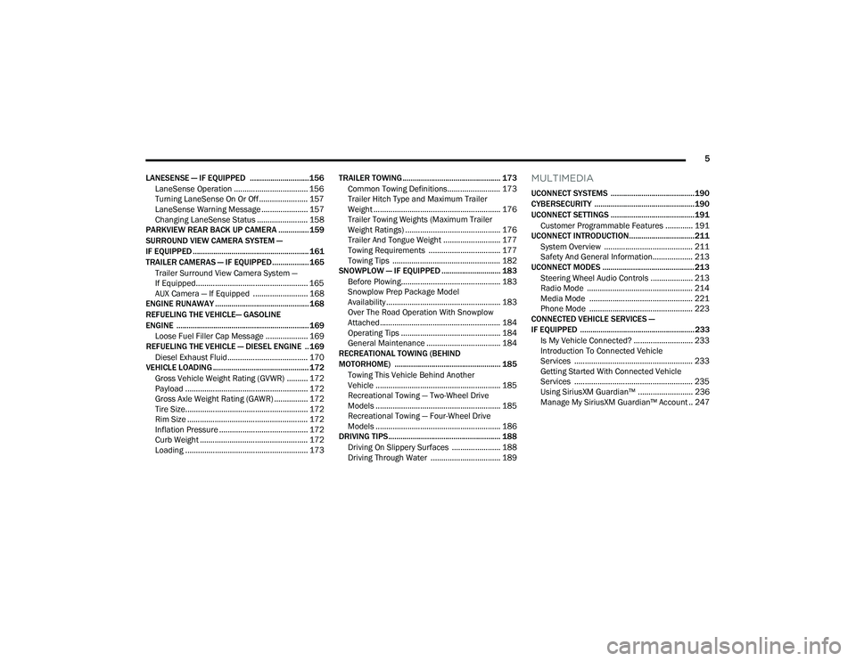
LANESENSE — IF EQUIPPED ............................. 156 LaneSense Operation ................................... 156Turning LaneSense On Or Off ....................... 157
LaneSense Warning Message ...................... 157Changing LaneSense Status ........................ 158
PARKVIEW REAR BACK UP CAMERA ............... 159
SURROUND VIEW CAMERA SYSTEM —
IF EQUIPPED ......................................................... 161
TRAILER CAMERAS — IF EQUIPPED..................165
Trailer Surround View Camera System —
If Equipped..................................................... 165
AUX Camera — If Equipped .......................... 168
ENGINE RUNAWAY .............................................. 168
REFUELING THE VEHICLE— GASOLINE
ENGINE ................................................................. 169
Loose Fuel Filler Cap Message .................... 169
REFUELING THE VEHICLE — DIESEL ENGINE .. 169
Diesel Exhaust Fluid ...................................... 170
VEHICLE LOADING ............................................... 172
Gross Vehicle Weight Rating (GVWR) .......... 172
Payload .......................................................... 172
Gross Axle Weight Rating (GAWR) ................ 172
Tire Size.......................................................... 172
Rim Size ......................................................... 172
Inflation Pressure .......................................... 172
Curb Weight ................................................... 172Loading .......................................................... 173 TRAILER TOWING ................................................ 173
Common Towing Definitions......................... 173
Trailer Hitch Type and Maximum Trailer
Weight ............................................................ 176
Trailer Towing Weights (Maximum Trailer
Weight Ratings) ............................................. 176Trailer And Tongue Weight ........................... 177Towing Requirements .................................. 177
Towing Tips ................................................... 182
SNOWPLOW — IF EQUIPPED ............................. 183
Before Plowing............................................... 183
Snowplow Prep Package Model
Availability ...................................................... 183
Over The Road Operation With Snowplow
Attached......................................................... 184
Operating Tips ............................................... 184
General Maintenance ................................... 184
RECREATIONAL TOWING (BEHIND
MOTORHOME) .................................................... 185
Towing This Vehicle Behind Another
Vehicle ........................................................... 185
Recreational Towing — Two-Wheel Drive
Models ........................................................... 185
Recreational Towing — Four-Wheel Drive
Models ........................................................... 186
DRIVING TIPS ....................................................... 188
Driving On Slippery Surfaces ....................... 188
Driving Through Water ................................. 189
MULTIMEDIA
UCONNECT SYSTEMS ......................................... 190
CYBERSECURITY ................................................. 190
UCONNECT SETTINGS ......................................... 191 Customer Programmable Features ............. 191
UCONNECT INTRODUCTION................................ 211
System Overview .......................................... 211Safety And General Information................... 213
UCONNECT MODES ............................................. 213
Steering Wheel Audio Controls .................... 213
Radio Mode .................................................. 214Media Mode ................................................. 221
Phone Mode ................................................. 223
CONNECTED VEHICLE SERVICES —
IF EQUIPPED ........................................................ 233
Is My Vehicle Connected? ............................ 233
Introduction To Connected Vehicle
Services ........................................................ 233
Getting Started With Connected Vehicle
Services ........................................................ 235
Using SiriusXM Guardian™ .......................... 236
Manage My SiriusXM Guardian™ Account .. 247
22_DPF_OM_EN_USC_t.book Page 5
Page 9 of 428
7
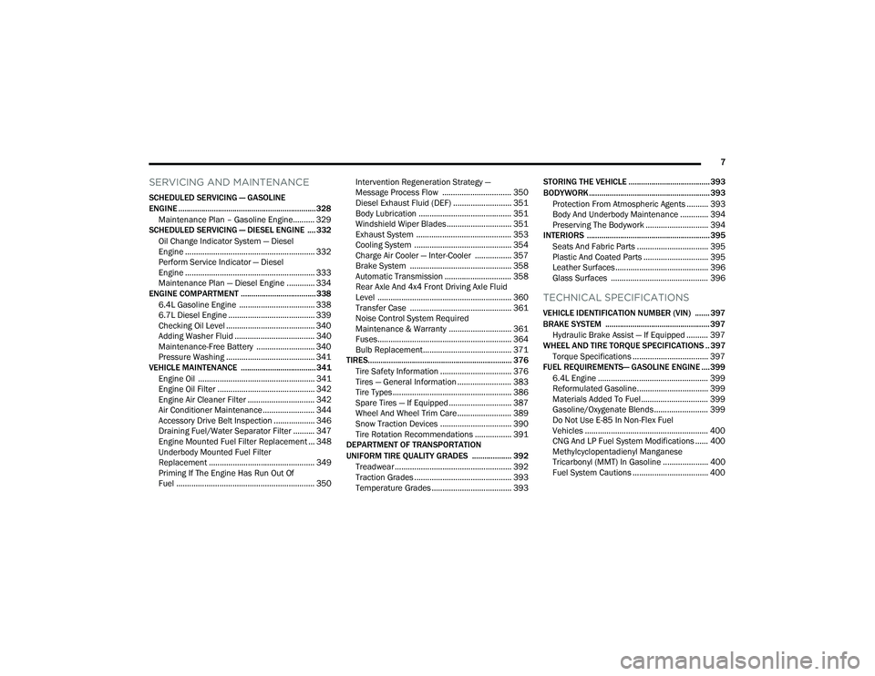
SERVICING AND MAINTENANCE
SCHEDULED SERVICING — GASOLINE
ENGINE .................................................................. 328Maintenance Plan – Gasoline Engine.......... 329
SCHEDULED SERVICING — DIESEL ENGINE .... 332
Oil Change Indicator System — Diesel
Engine ............................................................ 332
Perform Service Indicator — Diesel
Engine ............................................................ 333
Maintenance Plan — Diesel Engine ............. 334
ENGINE COMPARTMENT .................................... 338
6.4L Gasoline Engine ................................... 3386.7L Diesel Engine ........................................ 339
Checking Oil Level ......................................... 340
Adding Washer Fluid ..................................... 340
Maintenance-Free Battery ........................... 340
Pressure Washing ......................................... 341
VEHICLE MAINTENANCE .................................... 341
Engine Oil ...................................................... 341Engine Oil Filter ............................................. 342
Engine Air Cleaner Filter ............................... 342
Air Conditioner Maintenance ........................ 344
Accessory Drive Belt Inspection ................... 346
Draining Fuel/Water Separator Filter .......... 347
Engine Mounted Fuel Filter Replacement ... 348
Underbody Mounted Fuel Filter
Replacement ................................................. 349
Priming If The Engine Has Run Out Of
Fuel ................................................................ 350 Intervention Regeneration Strategy —
Message Process Flow ................................ 350
Diesel Exhaust Fluid (DEF) ........................... 351Body Lubrication ........................................... 351Windshield Wiper Blades.............................. 351Exhaust System ............................................ 353
Cooling System ............................................. 354Charge Air Cooler — Inter-Cooler ................. 357
Brake System ............................................... 358
Automatic Transmission ............................... 358
Rear Axle And 4x4 Front Driving Axle Fluid
Level .............................................................. 360
Transfer Case ............................................... 361
Noise Control System Required
Maintenance & Warranty ............................. 361
Fuses.............................................................. 364
Bulb Replacement......................................... 371
TIRES..................................................................... 376
Tire Safety Information ................................. 376
Tires — General Information ......................... 383
Tire Types....................................................... 386
Spare Tires — If Equipped ............................. 387
Wheel And Wheel Trim Care ......................... 389
Snow Traction Devices ................................. 390
Tire Rotation Recommendations ................. 391
DEPARTMENT OF TRANSPORTATION
UNIFORM TIRE QUALITY GRADES ................... 392
Treadwear ...................................................... 392
Traction Grades ............................................. 393Temperature Grades ..................................... 393 STORING THE VEHICLE ....................................... 393
BODYWORK .......................................................... 393
Protection From Atmospheric Agents .......... 393
Body And Underbody Maintenance ............. 394
Preserving The Bodywork ............................. 394
INTERIORS ........................................................... 395
Seats And Fabric Parts ................................. 395
Plastic And Coated Parts .............................. 395
Leather Surfaces........................................... 396
Glass Surfaces ............................................. 396
TECHNICAL SPECIFICATIONS
VEHICLE IDENTIFICATION NUMBER (VIN) ....... 397
BRAKE SYSTEM .................................................. 397Hydraulic Brake Assist — If Equipped .......... 397
WHEEL AND TIRE TORQUE SPECIFICATIONS .. 397
Torque Specifications ................................... 397
FUEL REQUIREMENTS— GASOLINE ENGINE .... 399
6.4L Engine ................................................... 399
Reformulated Gasoline................................. 399
Materials Added To Fuel ............................... 399
Gasoline/Oxygenate Blends ......................... 399
Do Not Use E-85 In Non-Flex Fuel
Vehicles ......................................................... 400
CNG And LP Fuel System Modifications ...... 400Methylcyclopentadienyl Manganese
Tricarbonyl (MMT) In Gasoline ..................... 400Fuel System Cautions ................................... 400
22_DPF_OM_EN_USC_t.book Page 7
Page 11 of 428

9
INTRODUCTION
Dear Customer,
Congratulations on the purchase of your new Ram. Be assured that it represents precision workmanship, distinctive styling, and high quality.
This is a specialized utility vehicle. It can go places and perform tasks that are not intended for conventional passenger vehicles. It handles and maneuvers
differently from many passenger vehicles both on-road and off-road, so take time to become familiar with your vehicle. If equipped, the two-wheel drive version
of this vehicle was designed for on-road use only. It is not intended for off-road driving or use in other severe conditions suited for a four-wheel drive vehicle.
Before you start to drive this vehicle, read the Owner’s Manual. Be sure you are familiar with all vehicle controls, particularly those used for braking, steering,
transmission, and transfer case shifting. Learn how your vehicle handles on different road surfaces. Your driving skills will improve with experience. When driving
off-road, or working the vehicle, don’t overload the vehicle or expect the vehicle to overcome the natural laws of physics. Always observe federal, state, provincial
and local laws wherever you drive. As with other vehicles of this type, failure to operate this vehicle correctly may result in loss of control or a collision Úpage 188.
This Owner's Manual has been prepared with the assistance of service and engineering specialists to acquaint you with the operation and maintenance of your
vehicle. It is supplemented by customer-oriented documents. Within this information, you will find a description of the services that FCA US LLC offers to its
customers as well as the details of the terms and conditions for maintaining its validity. Please take the time to read all of these publications carefully before
driving your vehicle for the first time. Following the instructions, recommendations, tips, and important warnings in this manual will help ensure safe and
enjoyable operation of your vehicle.
This Owner’s Manual describes all versions of this vehicle. Options and equipment dedicated to specific markets or versions are not expressly indicated in the
text. Therefore, you should only consider the information that is related to the trim level, engine, and version that you have purchased. Any content introduced
throughout the Owner’s Information, which may or may not be applicable to your vehicle, will be identified with the wording “If Equipped”. All data contained in
this publication are intended to help you use your vehicle in the best possible way. FCA US LLC aims at a constant improvement of the vehicles produced. For
this reason, it reserves the right to make changes to the model described for technical and/or commercial reasons. For further information, contact an authorized
dealer.
When it comes to service, remember that authorized dealers know your Ram best, have factory-trained technicians, genuine Mopar® parts, and care about your
satisfaction.1
22_DPF_OM_EN_USC_t.book Page 9
Page 92 of 428

90GETTING TO KNOW YOUR INSTRUMENT PANEL
Commercial Settings — If Equipped
Commercial Settings allows the driver to set and
recall additional features when the transmission is
in PARK.
Push and release the up or down arrow
button until Commercial Settings displays in the
instrument cluster display.
Follow the prompts to enter the required PIN and
enter the Commercial Settings submenu.
NOTE:If your vehicle is equipped with a touchscreen
radio, “Commercial Settings” will replace “Vehicle
Settings” in the instrument cluster display. The
Commercial Settings menu will only include the
settings below Ú page 191.
Commercial Settings allows you to access the
following features (if equipped):
Power Take Off (PTO)
Remote Ignition
Idle Control
Backup Alarm
ParkSense
Aux Switches
PIN Setup
NOTE:If the vehicle’s PIN is forgotten or not known, see
an authorized dealer to have the PIN reset.
DIESEL MESSAGES AND WARNINGS
Diesel Particulate Filter (DPF) Messages
The Cummins® diesel engine meets all diesel
emissions standards, resulting in one of the lowest
emitting diesel engines ever produced. To achieve
these emissions standards, your vehicle is
equipped with a state-of-the-art engine and
exhaust system. These systems are seamlessly
integrated into your vehicle and managed by the
Powertrain Control Module (PCM). The PCM
manages engine combustion to allow the exhaust
system’s catalyst to trap and burn Particulate
Matter (PM) pollutants, with no input or interaction
on your part.
Your vehicle has the ability to alert you to
additional maintenance required on your vehicle or
engine. The following messages may display in
your instrument cluster display:
Perform Service — Your vehicle will require emis -
sions maintenance at a set interval. To help
remind you when this maintenance is due, the
instrument cluster display will display “Perform
Service”. When the “Perform Service” message
is displayed in the instrument cluster display it is
necessary to have the emissions maintenance
performed. Emissions maintenance may
include replacing the Closed Crankcase Ventila -
tion (CCV) filter element. The procedure for
clearing and resetting the "Perform Service"
indicator message is located in the appropriate
Service Information.
Exhaust System — Regeneration Required
Now — "Exhaust Filter XX% Full Safely Drive at
Highway Speeds to Remedy" will be displayed in
the instrument cluster display if the exhaust
particulate filter reaches 80% of its maximum
storage capacity. Under conditions of exclusive
short duration and low speed driving cycles,
your Cummins® diesel engine and exhaust
after-treatment system may never reach the
conditions required to remove the trapped PM.
If this occurs, the “Exhaust Filter XX% Full Safely
Drive at Highway Speeds to Remedy” message
will be displayed in the instrument cluster
display. If this message is displayed, you will
hear one chime to assist in alerting you of this
condition
WARNING!
A hot exhaust system can start a fire if you park
over materials that can burn. Such materials
might be grass or leaves coming into contact
with your exhaust system. Do not park or
operate your vehicle in areas where your
exhaust system can contact anything that can
burn.
22_DPF_OM_EN_USC_t.book Page 90
Page 101 of 428

GETTING TO KNOW YOUR INSTRUMENT PANEL99
Low Fuel Warning Light
When the fuel level reaches
approximately 3.2 gal (12 L) this light will
turn on, and remain on until fuel is
added.
A single warning chime will sound with Low Fuel
Warning.
Low Coolant Level Warning Light
This telltale will turn on to indicate the
vehicle coolant level is low Ú page 341.
Loose Fuel Filler Cap Warning Light —
If Equipped
This warning light will illuminate when the
fuel filler cap is loose. Properly close the
filler cap to disengage the light. If the
light does not turn off, please see an
authorized dealer.
Tire Pressure Monitoring System (TPMS)
Warning Light — If Equipped
The warning light switches on and a
message is displayed to indicate that the
tire pressure is lower than the
recommended value and/or that slow
pressure loss is occurring. In these cases, optimal
tire duration and fuel consumption may not be
guaranteed. Should one or more tires be in the condition
mentioned above, the display will show the
indications corresponding to each tire.
Each tire, including the spare (if provided), should
be checked monthly when cold and inflated to the
inflation pressure recommended by the vehicle
manufacturer on the vehicle placard or tire
inflation pressure label. If your vehicle has tires of
a different size than the size indicated on the
vehicle placard or tire inflation pressure label, you
should determine the proper tire inflation pressure
for those tires.
As an added safety feature, your vehicle has been
equipped with a TPMS that illuminates a low tire
pressure telltale when one or more of your tires is
significantly underinflated. Accordingly, when the
low tire pressure telltale illuminates, you should
stop and check your tires as soon as possible, and
inflate them to the proper pressure. Driving on a
significantly underinflated tire causes the tire to
overheat and can lead to tire failure. Underinflation also reduces fuel efficiency and tire tread life, and
may affect the vehicle’s handling and stopping
ability.
Please note that the TPMS is not a substitute for
proper tire maintenance, and it is the driver’s
responsibility to maintain correct tire pressure,
even if underinflation has not reached the level to
trigger illumination of the TPMS low tire pressure
telltale.
Your vehicle has also been equipped with a TPMS
malfunction indicator to indicate when the system
is not operating properly. The TPMS malfunction
indicator is combined with the low tire pressure
telltale. When the system detects a malfunction,
the telltale will flash for approximately one minute
and then remain continuously illuminated. This
sequence will continue upon subsequent vehicle
start-ups as long as the malfunction exists. When
the malfunction indicator is illuminated, the
system may not be able to detect or signal low tire
pressure as intended. TPMS malfunctions may
occur for a variety of reasons, including the
installation of replacement or alternate tires or
wheels on the vehicle that prevent the TPMS from
functioning properly. Always check the TPMS
malfunction telltale after replacing one or more
tires or wheels on your vehicle to ensure that the
replacement or alternate tires and wheels allow
the TPMS to continue to function properly.
CAUTION!
Do not continue driving with one or more flat
tires as handling may be compromised. Stop the
vehicle, avoiding sharp braking and steering. If a
tire puncture occurs, repair immediately using
the dedicated tire repair kit and contact an
authorized dealer as soon as possible.
3
22_DPF_OM_EN_USC_t.book Page 99
Page 106 of 428

104GETTING TO KNOW YOUR INSTRUMENT PANEL
EMISSIONS INSPECTION AND
MAINTENANCE PROGRAMS
In some localities, it may be a legal requirement to
pass an inspection of your vehicle's emissions
control system. Failure to pass could prevent
vehicle registration.
For states that require an Inspection and
Maintenance (I/M), this check verifies
the Malfunction Indicator Light (MIL) is
functioning and is not on when the
engine is running, and that the OBD II system is
ready for testing.
Normally, the OBD II system will be ready. The
OBD II system may not be ready if your vehicle was
recently serviced, recently had a depleted battery
or a battery replacement. If the OBD II system
should be determined not ready for the I/M test,
your vehicle may fail the test.
Your vehicle has a simple ignition actuated test,
which you can use prior to going to the test station.
To check if your vehicle's OBD II system is ready,
you must do the following:
1. Cycle the ignition switch to the ON position,
but do not crank or start the engine.
NOTE:If you crank or start the engine, you will have to
start this test over.
2. As soon as you cycle the ignition switch to the ON position, you will see the Malfunction
Indicator Light (MIL) symbol come on as part of
a normal bulb check.
3. Approximately 15 seconds later, one of two things will happen:
The MIL will flash for about 10 seconds and
then return to being fully illuminated until
you turn OFF the ignition or start the engine.
This means that your vehicle's OBD II
system is not ready and you should not
proceed to the I/M station.
The MIL will not flash at all and will remain
fully illuminated until you place the ignition
in the off position or start the engine. This
means that your vehicle's OBD II system is
ready and you can proceed to the I/M
station. If your OBD II system is
not ready, you should see
an authorized dealer or repair facility. If your
vehicle was recently serviced or had a battery
failure or replacement, you may need to do nothing
more than drive your vehicle as you normally would
in order for your OBD II system to update. A
recheck with the above test routine may then
indicate that the system is now ready.
Regardless of whether your vehicle's OBD II system
is ready or not, if the MIL is illuminated during
normal vehicle operation you should have your
vehicle serviced before going to the I/M station.
The I/M station can fail your vehicle because the
MIL is on with the engine running.
22_DPF_OM_EN_USC_t.book Page 104
Page 150 of 428
148STARTING AND OPERATING
Trailer Detect — If Equipped
When a trailer is detected, the ACC system
automatically defaults to the longest setting (four
bars). The setting can be overridden by pushing the
Distance Button on the steering wheel.
Overtake Aid
When driving with ACC engaged and following a
vehicle, the system will provide an additional
acceleration up to the ACC set speed to assist in
passing the vehicle. This additional acceleration is
triggered when the driver utilizes the left turn
signal and will only be active when passing on the
left hand side.
ACC Operation At Stop
If the ACC system brings your vehicle to a standstill
while following a vehicle ahead, your vehicle will
resume motion, without any driver interaction, if
the vehicle ahead starts moving within two
seconds of your vehicle coming to a standstill.
If the vehicle in front does not start moving within
two seconds of your vehicle coming to a standstill,
the ACC with Stop system will cancel and the
brakes will release. A cancel message will display
on the instrument cluster display and produce a
warning chime. The driver must now manually
operate the vehicle’s accelerator and brakes.
While ACC with Stop is holding your vehicle at a
standstill, if the driver seat belt is unbuckled or the
driver door is opened, the ACC with Stop system will cancel and the brakes will release. A cancel
message will display on the instrument cluster
display and produce a warning chime. The driver
must now manually operate the vehicle’s
accelerator and brakes.
Display Warnings And Maintenance
“WIPE FRONT RADAR SENSOR IN FRONT OF
VEHICLE” WARNING
The “ACC/FCW Unavailable Wipe Front Radar
Sensor” warning will display and a chime will
sound when conditions temporarily limit system
performance.
This most often occurs at times of poor visibility,
such as in snow or heavy rain. The ACC system may
also become temporarily blinded due to
obstructions, such as mud, dirt or ice. In these
cases, the instrument cluster display will display
“ACC/FCW Unavailable Wipe Front Radar Sensor”
and the system will deactivate.
This message can sometimes be displayed while
driving in highly reflective areas (i.e. ice and snow,
or tunnels with reflective tiles). The ACC system will
recover after the vehicle has left these areas.
Under rare conditions, when the radar is not
tracking any vehicles or objects in its path this
warning may temporarily occur.
NOTE:If the “ACC/FCW Unavailable Wipe Front Radar
Sensor” warning is active, Fixed Speed Cruise
Control is still available.
If weather conditions are not a factor, the driver
should examine the sensor. It may require cleaning
or removal of an obstruction. The sensor is located
in the camera in the center of the windshield, on
the forward side of the rearview mirror.
To keep the ACC system operating properly, it is
important to note the following maintenance
items:
Always keep the sensor clean. Carefully clear
the windshield.
Do not remove any screws from the sensor.
Doing so could cause an ACC system malfunc
-
tion or failure and require a sensor realignment.
Do not attach or install any accessories near the
sensor, including transparent material or after -
market grilles. Doing so could cause an ACC
system failure or malfunction.
WARNING!
When the ACC system is resumed, the driver
must ensure that there are no pedestrians,
vehicles or objects in the path of the vehicle.
Failure to follow these warnings can result in a
collision and death or serious personal injury.
22_DPF_OM_EN_USC_t.book Page 148
Page 179 of 428

STARTING AND OPERATING177
(Continued)
(Continued)
TRAILER AND TONGUE WEIGHT
Never exceed the maximum tongue weight
stamped on your bumper or trailer hitch.
Weight Distribution
Consider the following items when computing the
weight on the rear axle of the vehicle:The tongue weight of the trailer.
The weight of any other type of cargo or equip
-
ment put in or on your vehicle.
The weight of the driver and all passengers.
NOTE:Remember that everything put into or on the trailer
adds to the load on your vehicle. Also, additional
factory-installed options or dealer-installed options
must be considered as part of the total load on
your vehicle. For the maximum combined weight of
occupants and cargo for your vehicle Úpage 380.
TOWING REQUIREMENTS
To promote proper break-in of your new vehicle
drivetrain components, the following guidelines
are recommended. Perform the maintenance listed in the “Scheduled
Servicing” Ú
page 328. When towing a trailer,
never exceed the GAWR or GCWR ratings.CAUTION!
Always load a trailer with 60% of the weight in
the front of the trailer. This places 10% of the
GTW on the tow hitch of your vehicle. Loads
balanced over the wheels or heavier in the rear
can cause the trailer to sway severely side to
side which will cause loss of control of the
vehicle and trailer. Failure to load trailers heavier
in front is the cause of many trailer collisions.
CAUTION!
Do not tow a trailer at all during the first
500 miles (805 km) the new vehicle is driven.
The engine, axle or other parts could be
damaged.
Then, during the first 500 miles (805 km) that
a trailer is towed, do not drive over 50 mph
(80 km/h) and do not make starts at full
throttle. This helps the engine and other parts
of the vehicle wear in at the heavier loads.
WARNING!
Make certain that the load is secured in the
trailer and will not shift during travel. When
trailering cargo that is not fully secured,
dynamic load shifts can occur that may be
difficult for the driver to control. You could lose
control of your vehicle and have a collision.
When hauling cargo or towing a trailer, do not
overload your vehicle or trailer. Overloading
can cause a loss of control, poor performance
or damage to brakes, axle, engine, transmis -
sion, steering, suspension, chassis structure
or tires.
CAUTION!
4
22_DPF_OM_EN_USC_t.book Page 177