turn signal RAM CHASSIS CAB 2022 Owners Manual
[x] Cancel search | Manufacturer: RAM, Model Year: 2022, Model line: CHASSIS CAB, Model: RAM CHASSIS CAB 2022Pages: 428, PDF Size: 20.18 MB
Page 5 of 428
3
EXTERIOR LIGHTS.................................................. 47 Headlight Switch...............................................47
Multifunction Lever ..........................................47
Daytime Running Lights (DRLs) ......................48
High/Low Beam Switch....................................48
Automatic High Beam Headlamp Control —
If Equipped........................................................48
Flash-To-Pass....................................................48
Automatic Headlights — If Equipped ..............48
Directional LED Headlamp System —
If Equipped........................................................49
Parking Lights ...................................................49
Headlights On With Wipers ..............................49
Headlight Delay ................................................49
Lights-On Reminder..........................................49
Front Fog Lights — If Equipped .......................50
Turn Signals .....................................................50
Lane Change Assist — If Equipped ..................50
Cargo Lights/Trailer Spotter Lights —
If Equipped........................................................50
Battery Saver ....................................................51
INTERIOR LIGHTS ................................................. 51
Courtesy Lights .................................................51
Illuminated Entry .............................................52
WINDSHIELD WIPERS AND WASHERS .............. 53
Windshield Wiper Operation ...........................53
Rain Sensing Wipers — If Equipped ...............54 CLIMATE CONTROLS .............................................54
Automatic Climate Control Descriptions And
Functions ..........................................................54
Manual Climate Control Descriptions And
Functions ..........................................................58
Automatic Temperature Control (ATC) ............60
Climate Voice Recognition — If Equipped .......60
Operating Tips .................................................60
INTERIOR STORAGE AND EQUIPMENT ............... 61
Storage..............................................................61
USB/AUX Control ..............................................66
Electrical Power Outlets ...................................68
Power Inverter — If Equipped ..........................69
Wireless Charging Pad — If Equipped ............70
WINDOWS ..............................................................71
Power Windows — If Equipped ........................71
Automatic Window Features — If Equipped....71
Reset Auto-Up ..................................................72
Window Lockout Switch — If Equipped ...........72
Power Sliding Rear Window — If Equipped ....72
Manual Sliding Rear Window — If Equipped...72
Wind Buffeting .................................................72
HOOD .......................................................................73
To Open The Hood ...........................................73
To Close The Hood ...........................................73
GETTING TO KNOW YOUR
INSTRUMENT PANEL
BASE / MIDLINE INSTRUMENT CLUSTER —
GASOLINE ............................................................... 74Base / Midline Instrument Cluster
Descriptions...................................................... 75
PREMIUM INSTRUMENT CLUSTER —
GASOLINE ............................................................... 76
Premium Instrument Cluster Descriptions ..... 77
BASE / MIDLINE INSTRUMENT CLUSTER —
DIESEL .................................................................... 78
Diesel Instrument Cluster ............................... 79
PREMIUM INSTRUMENT CLUSTER — DIESEL ... 80
Diesel Instrument Cluster ............................... 81
INSTRUMENT CLUSTER DISPLAY ........................ 81
Instrument Cluster Display And Controls........ 82
Oil Life Reset ................................................... 82
Display Menu Items ......................................... 83
Diesel Messages And Warnings ...................... 90
Battery Saver On/Battery Saver Mode
Message — Electrical Load Reduction
Actions — If Equipped ...................................... 93
WARNING LIGHTS AND MESSAGES ................... 94
Red Warning Lights ..........................................94
Yellow Warning Lights ...................................... 97
Yellow Indicator Lights .................................. 100 Green Indicator Lights .................................. 101White Indicator Lights ................................... 102
Blue Indicator Lights ..................................... 103
22_DPF_OM_EN_USC_t.book Page 3
Page 16 of 428
14
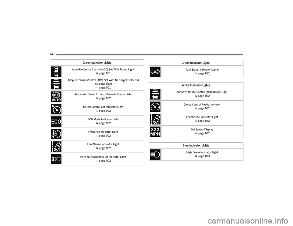
Green Indicator Lights
Adaptive Cruise Control (ACC) Set With Target Light Úpage 101
Adaptive Cruise Control (ACC) Set With No Target Detected Indicator Light
Ú page 101
Automatic Diesel Exhaust Brake Indicator Light Úpage 102
Cruise Control Set Indicator Light Úpage 102
ECO Mode Indicator Light Úpage 102
Front Fog Indicator Light Úpage 102
LaneSense Indicator Light Úpage 102
Parking/Headlights On Indicator Light Úpage 102Turn Signal Indicator Lights
Úpage 102
White Indicator Lights
Adaptive Cruise Control (ACC) Ready Light
Úpage 102
Cruise Control Ready Indicator Úpage 102
LaneSense Indicator Light Úpage 102
Set Speed Display Ú page 102
Blue Indicator Lights
High Beam Indicator Light
Úpage 103
Green Indicator Lights
22_DPF_OM_EN_USC_t.book Page 14
Page 17 of 428
15
GETTING TO KNOW YOUR VEHICLE
KEYS
KEY FOB
Your vehicle is equipped with a key fob which
supports Remote Keyless Entry (RKE) (if equipped)
and Keyless Enter ‘n Go™ (if equipped).
If the vehicle is equipped with remote power door
locks, the key fob allows you to lock or unlock all
doors, as well as activate the Panic Alarm, from
distances up to approximately 66 ft (20 m). The
key fob does not need to be pointed at the vehicle
to activate the system.
NOTE:
The key fob’s wireless signal may be blocked if
the key fob is located next to a mobile phone,
laptop, or other electronic device. This may
result in poor performance.
The key fob should not be placed next to the
wireless charging pad (if equipped).
In the ON/RUN position, all key fob buttons will
work until the vehicle reaches 2 mph (4 km/h).
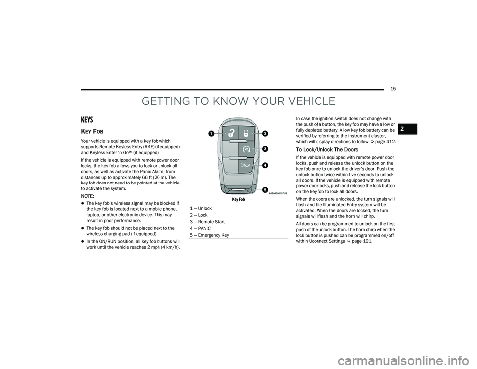
Key Fob
In case the ignition switch does not change with
the push of a button, the key fob may have a low or
fully depleted battery. A low key fob battery can be
verified by referring to the instrument cluster,
which will display directions to follow
Úpage 412.
To Lock/Unlock The Doors
If the vehicle is equipped with remote power door
locks, push and release the unlock button on the
key fob once to unlock the driver’s door. Push the
unlock button twice within five seconds to unlock
all doors. If the vehicle is equipped with remote
power door locks, push and release the lock button
on the key fob to lock all doors.
When the doors are unlocked, the turn signals will
flash and the Illuminated Entry system will be
activated. When the doors are locked, the turn
signals will flash and the horn will chirp.
All doors can be programmed to unlock on the first
push of the unlock button. The horn chirp when the
lock button is pushed can be programmed on/off
within Uconnect Settings Ú page 191.
1 — Unlock
2 — Lock
3 — Remote Start
4 — PANIC
5 — Emergency Key
2
22_DPF_OM_EN_USC_t.book Page 15
Page 25 of 428

GETTING TO KNOW YOUR VEHICLE23
VEHICLE SECURITY SYSTEM — IF EQUIPPED
The Vehicle Security system monitors the vehicle
doors and ignition for unauthorized operation.
When the Vehicle Security system is activated,
interior switches for door locks are disabled. If
something triggers the alarm, the Vehicle Security
system will provide the following audible and
visible signals:
The horn will pulse
The turn signals will flash
The Vehicle Security Light in the instrument
cluster will flash
TO ARM THE SYSTEM
Follow these steps to arm the Vehicle Security
system:
1. Make sure the vehicle’s ignition is placed in
the OFF position.
For vehicles equipped with Keyless Entry,
make sure the vehicle’s keyless ignition
system is OFF.
2. Perform one of the following methods to lock the vehicle:
Push the lock button on the interior power
door lock switch with the driver and/or
passenger door open.
Push the lock button on the exterior Passive
Entry door handle with a valid key fob avail -
able in the same exterior zone Ú page 25.
Push the lock button on the key fob.
3. If any doors are open, close them.
The Vehicle Security system will set when you use
the power door locks, or use the key fob to lock the
doors. After all the doors are locked and closed,
the Vehicle Security Light, in the instrument panel
cluster, will flash rapidly for about 16 seconds to
indicate that the alarm is being set. After the alarm
is set, the Vehicle Security Light will flash at a
slower rate to indicate that the system is armed.
TO DISARM THE SYSTEM
The Vehicle Security system can be disarmed using
any of the following methods:
1. Push the unlock button on the key fob.
2. Grab the Passive Entry door handle with a valid key fob within 5 ft (1.5 m) of the Passive Entry
door handle (if equipped) Ú page 25.
3. Cycle the ignition out of the OFF position. The Vehicle Security system is designed to protect
your vehicle. However, you can create conditions
where the system will give you a false alarm. If one
of the previously described arming sequences has
occurred, the Vehicle Security system will arm
regardless of whether you are in the vehicle or not.
If you remain in the vehicle and open a door, the
alarm will sound. If this occurs, disarm the Vehicle
Security system.
If the Vehicle Security system is armed and the
battery becomes disconnected, the Vehicle
Security system will remain armed when the
battery is reconnected; the exterior lights will flash,
and the horn will sound. If this occurs, disarm the
Vehicle Security system.REARMING OF THE SYSTEM
If something triggers the alarm, and no action is
taken to disarm it, the Vehicle Security system will
turn the horn off after a 29 second cycle (with five
seconds between cycles and up to eight cycles if
the trigger remains active), and then rearm itself.
SECURITY SYSTEM MANUAL OVERRIDE
The Vehicle Security system will not arm if you lock
the doors using the manual door lock.
2
22_DPF_OM_EN_USC_t.book Page 23
Page 48 of 428

46GETTING TO KNOW YOUR VEHICLE
3. Continue to press and hold the HomeLink® button, while you press and release (cycle)
your hand-held transmitter every two seconds
until HomeLink® has successfully accepted
the frequency signal. The indicator light will
flash slowly and then rapidly when fully
trained.
4. Watch for the HomeLink® indicator to change flash rates. When it changes, it is
programmed. It may take up to 30 seconds or
longer in rare cases. The garage door may
open and close while you are programming.
5. Press and hold the programmed HomeLink® button and observe the indicator light.
NOTE:
If the indicator light stays on constantly,
programming is complete and the garage
door/device should activate when the
HomeLink® button is pressed.
To program the two remaining HomeLink®
buttons, repeat each step for each
remaining button. DO NOT erase the chan -
nels.
If you unplugged the garage door opener/device
for programming, plug it back in at this time. Reprogramming A Single HomeLink® Button
(Canadian/Gate Operator)
To reprogram a channel that has been previously
trained, follow these steps:
1. Place the ignition in the ON/RUN position.
2. Press and hold the desired HomeLink® button
until the indicator light begins to flash after
20 seconds. Do not release the button.
3. Without releasing the button, proceed with “Canadian/Gate Operator Programming” step
2 and follow all remaining steps.
SECURITY
It is advised to erase all channels before you sell or
turn in your vehicle.
To do this, push and hold the two outside buttons
for 20 seconds until the indicator flashes. Note
that all channels will be erased. Individual
channels cannot be erased.
The HomeLink® Universal Transceiver is disabled
when the Vehicle Security system is active.
TROUBLESHOOTING TIPS
If you are having trouble programming
HomeLink®, here are some of the most common
solutions:
Replace the battery in the Garage Door Opener
hand-held transmitter.
Push the LEARN button on the Garage Door
Opener to complete the training for a Rolling
Code.
Did you unplug the device for programming and
remember to plug it back in?
If you have any problems, or require assistance,
please call toll-free 1-800-355-3515 or, on the
Internet at HomeLink.com for information or
assistance.
WARNING!
Vehicle exhaust contains carbon monoxide, a
dangerous gas. Do not run your vehicle in the
garage while programming the transceiver.
Exhaust gas can cause serious injury or death.
Your motorized door or gate will open and
close while you are programming the universal
transceiver. Do not program the transceiver if
people, pets or other objects are in the path of
the door or gate. Only use this transceiver with
a garage door opener that has a “stop and
reverse” feature as required by Federal safety
standards. This includes most garage door
opener models manufactured after 1982. Do
not use a garage door opener without these
safety features.
22_DPF_OM_EN_USC_t.book Page 46
Page 50 of 428
48GETTING TO KNOW YOUR VEHICLE
DAYTIME RUNNING LIGHTS (DRLS)
The Daytime Running Lights (DRLs) come on
whenever the engine is running, and the low
beams are not on. The lights will remain on until
the ignition is placed in the OFF or ACC position, or
the parking brake is engaged.
NOTE:
For vehicles sold in Canada, the Daytime
Running Lights will automatically deactivate
when the front fog lights are turned on.
If allowed by law in the country in which the
vehicle was purchased, the Daytime Running
Lights can be turned on and off using the
Uconnect system Úpage 191.
On some vehicles, the Daytime Running Lights
may deactivate, or reduce intensity, on one side
of the vehicle (when a turn signal is activated on
that side), or on both sides of the vehicle (when
the hazard warning lights are activated).
HIGH/LOW BEAM SWITCH
Push the multifunction lever toward the instrument
panel to switch the headlights to high beam.
Pulling the multifunction lever back toward the
steering wheel will turn the low beams back on.
AUTOMATIC HIGH BEAM HEADLAMP
C
ONTROL — IF EQUIPPED
The Automatic High Beam Headlamp Control
system provides increased forward lighting at night
by automating high beam control through the use
of a camera mounted on the inside rearview mirror
or a windshield mounted camera. These cameras
detect vehicle specific light and automatically
switch from high beams to low beams until the
approaching vehicle is out of view.
NOTE:
The Automatic High Beam Headlamp Control
can be turned on or off by selecting “ON” under
“Auto Dim High Beams” within your Uconnect
Settings Ú page 191, as well as turning the
headlight switch to the AUTO position.
Broken, muddy, or obstructed headlights and
taillights of vehicles in the field of view will
cause headlights to remain on longer (closer to
the vehicle). Also, dirt, film, and other obstruc -
tions on the windshield or camera lens will
cause the system to function improperly.
If the windshield or Automatic High Beam Head -
lamp Control mirror is replaced, the mirror must
be re-aimed to ensure proper performance. See
a local authorized dealer.
To opt out of the Automatic High-Beam Sensi -
tivity Control (default) and enter Reduced
High-Beam Sensitivity Control (not recom -
mended), toggle the multifunction lever six full
on/off cycles within 10 seconds of ignition ON.
The system will return to the default setting
when the ignition is placed in the OFF position.
FLASH-TO-PASS
You can signal another vehicle with your headlights
by lightly pulling the multifunction lever toward you.
This will cause the high beam headlights to turn on,
and remain on, until the lever is released.
AUTOMATIC HEADLIGHTS — IF EQUIPPED
This system automatically turns your headlights on
or off based on ambient light levels. To turn the
system on, rotate the headlight switch to the AUTO
position.
When the system is on, the Headlight Delay feature
is also on. This means the headlights will stay on
for up to 90 seconds after you place the ignition
into the OFF position. To turn the automatic
headlights off, turn the headlight switch out of the
AUTO position.
NOTE:The engine must be running before the headlights
will come on in the Automatic mode.
22_DPF_OM_EN_USC_t.book Page 48
Page 52 of 428

50GETTING TO KNOW YOUR VEHICLE
FRONT FOG LIGHTS — IF EQUIPPED
To activate the front fog lights, turn on the parking
lights or low beam headlights and push the fog
light switch located within the headlight switch.
Pushing the fog light switch a second time will turn
the front fog lights off.
Fog Light Switch
Fog Light Switch (Vehicles Sold In Canada Only)
TURN SIGNALS
Move the multifunction lever up or down to
activate the turn signals. The arrows on each side
of the instrument cluster flash to show proper
operation.
NOTE:If either light remains on and does not flash, or
there is a very fast flash rate, check for a defective
outside light bulb.
LANE CHANGE ASSIST — IF EQUIPPED
Lightly push the multifunction lever up or down,
without moving beyond the detent, and the turn
signal will flash three times then automatically turn
off.
CARGO LIGHTS/TRAILER SPOTTER
L
IGHTS — IF EQUIPPED
The cargo lights (if equipped) and trailer spotter
lights (if equipped) are turned on by pushing the
cargo lights button located on the lower half of the
headlight switch.
Cargo Lights Button On Headlight Switch
Cargo Lights Button (Vehicles Sold In Canada Only)
The cargo lights will turn on for approximately
60 seconds when a key fob unlock button is
pushed, as part of the Illuminated Entry feature.
When these lights are activated using the button
on the headlight switch, the trailer spotter lights
will remain illuminated when the vehicle
22_DPF_OM_EN_USC_t.book Page 50
Page 96 of 428
94GETTING TO KNOW YOUR INSTRUMENT PANEL
Loss of the battery charge may indicate one or
more of the following conditions:
The charging system cannot deliver enough
electrical power to the vehicle system because
the electrical loads are larger than the capability
of charging system. The charging system is still
functioning properly.
Turning on all possible vehicle electrical loads
(e.g. HVAC to max settings, exterior and interior
lights, overloaded power outlets +12 Volts,
115 Volt AC, USB ports) during certain driving
conditions (city driving, towing, frequent stop -
ping).
Installing options like additional lights, upfitter
electrical accessories, audio systems, alarms
and similar devices.
Unusual driving cycles (short trips separated by
long parking periods).
The vehicle was parked for an extended period
of time (weeks, months).
The battery was recently replaced and was not
charged completely.
The battery was discharged by an electrical load
left on when the vehicle was parked.
The battery was used for an extended period
with the engine not running to supply radio,
lights, chargers, +12 Volt portable appliances
like vacuum cleaners, game consoles and
similar devices. What to do when an electrical load reduction
action message is present (“Battery Saver On” or
“Battery Saver Mode”)
During a trip:
Reduce power to unnecessary loads if possible:
Turn off redundant lights (interior or exte
-
rior).
Check what may be plugged in to power
outlets +12 Volts, 115 Volt AC, USB ports.
Check HVAC settings (blower, temperature).
Check the audio settings (volume).
After a trip:
Check if any aftermarket equipment was
installed (additional lights, upfitter electrical
accessories, audio systems, alarms) and review
specifications if any (load and Ignition Off Draw
currents).
Evaluate the latest driving cycles (distance,
driving time and parking time).
The vehicle should have service performed if
the message is still present during consecutive
trips and the evaluation of the vehicle and
driving pattern did not help to identify the cause.
WARNING LIGHTS AND MESSAGES
The warning/indicator lights will illuminate in the
instrument panel together with a dedicated
message and/or acoustic signal when applicable.
These indications are indicative and precautionary
and as such must not be considered as exhaustive.
Always refer to the information in this chapter in
the event of a failure indication. All active telltales
will display first if applicable. The system check
menu may appear different based upon
equipment options and current vehicle status.
Some telltales are optional and may not appear.
RED WARNING LIGHTS
Seat Belt Reminder Warning Light
This warning light indicates when the
driver or passenger seat belt is
unbuckled. When the ignition is first
placed in the ON/RUN or ACC/ON/RUN
position and if the driver’s seat belt is unbuckled,
a chime will sound and the light will turn on. When
driving, if the driver or front passenger seat belt
remains unbuckled, the Seat Belt Reminder Light
will flash or remain on continuously and a chime
will sound Ú page 275.
22_DPF_OM_EN_USC_t.book Page 94
Page 100 of 428

98GETTING TO KNOW YOUR INSTRUMENT PANEL
When the engine is running, the MIL may flash to
alert serious conditions that could lead to
immediate loss of power or severe catalytic
converter damage. The vehicle should be serviced
by an authorized dealer as soon as possible if this
occurs.
Electronic Stability Control (ESC) Active
Warning Light — If Equipped
This warning light will indicate when the
ESC system is Active. The ESC Indicator
Light in the instrument cluster will come
on when the ignition is placed in the ON/
RUN or ACC/ON/RUN position, and when ESC is
activated. It should go out with the engine running.
If the ESC Indicator Light comes on continuously
with the engine running, a malfunction has been
detected in the ESC system. If this warning light
remains on after several ignition cycles, and the
vehicle has been driven several miles (kilometers)
at speeds greater than 30 mph (48 km/h), see an
authorized dealer as soon as possible to have the
problem diagnosed and corrected.
The ESC OFF Indicator Light and the ESC Indi -
cator Light come on momentarily each time the
ignition is placed in the ON/RUN or ACC/ON/
RUN position.
The ESC system will make buzzing or clicking
sounds when it is active. This is normal; the
sounds will stop when ESC becomes inactive.
This light will come on when the vehicle is in an
ESC event.
Electronic Stability Control (ESC) OFF
Warning Light — If Equipped
This warning light indicates the ESC is off.
Each time the ignition is turned to ON/
RUN or ACC/ON/RUN, the ESC system
will be on, even if it was turned off previously.
LaneSense Warning Light — If Equipped
The LaneSense system provides the
driver with visual and steering torque
warnings when the vehicle starts to drift
out of its lane unintentionally without the
use of a turn signal.
When the LaneSense system senses a lane drift
situation, the LaneSense indicator changes
from solid green to solid yellow.
When the LaneSense system senses the lane
has been approached and is in a lane departure
situation, the LaneSense indicator changes
from solid white/green to flashing yellow
Ú page 156.
Low Washer Fluid Warning Light —
If Equipped
This warning light will illuminate when the
windshield washer fluid is low
Úpage 338.
WARNING!
A malfunctioning catalytic converter, as
referenced above, can reach higher
temperatures than in normal operating
conditions. This can cause a fire if you drive
slowly or park over flammable substances such
as dry plants, wood, cardboard, etc. This could
result in death or serious injury to the driver,
occupants or others.
CAUTION!
Prolonged driving with the Malfunction Indicator
Light (MIL) on could cause damage to the
vehicle control system. It also could affect fuel
economy and driveability. If the MIL is flashing,
severe catalytic converter damage and power
loss will soon occur. Immediate service is
required.
22_DPF_OM_EN_USC_t.book Page 98
Page 101 of 428

GETTING TO KNOW YOUR INSTRUMENT PANEL99
Low Fuel Warning Light
When the fuel level reaches
approximately 3.2 gal (12 L) this light will
turn on, and remain on until fuel is
added.
A single warning chime will sound with Low Fuel
Warning.
Low Coolant Level Warning Light
This telltale will turn on to indicate the
vehicle coolant level is low Ú page 341.
Loose Fuel Filler Cap Warning Light —
If Equipped
This warning light will illuminate when the
fuel filler cap is loose. Properly close the
filler cap to disengage the light. If the
light does not turn off, please see an
authorized dealer.
Tire Pressure Monitoring System (TPMS)
Warning Light — If Equipped
The warning light switches on and a
message is displayed to indicate that the
tire pressure is lower than the
recommended value and/or that slow
pressure loss is occurring. In these cases, optimal
tire duration and fuel consumption may not be
guaranteed. Should one or more tires be in the condition
mentioned above, the display will show the
indications corresponding to each tire.
Each tire, including the spare (if provided), should
be checked monthly when cold and inflated to the
inflation pressure recommended by the vehicle
manufacturer on the vehicle placard or tire
inflation pressure label. If your vehicle has tires of
a different size than the size indicated on the
vehicle placard or tire inflation pressure label, you
should determine the proper tire inflation pressure
for those tires.
As an added safety feature, your vehicle has been
equipped with a TPMS that illuminates a low tire
pressure telltale when one or more of your tires is
significantly underinflated. Accordingly, when the
low tire pressure telltale illuminates, you should
stop and check your tires as soon as possible, and
inflate them to the proper pressure. Driving on a
significantly underinflated tire causes the tire to
overheat and can lead to tire failure. Underinflation also reduces fuel efficiency and tire tread life, and
may affect the vehicle’s handling and stopping
ability.
Please note that the TPMS is not a substitute for
proper tire maintenance, and it is the driver’s
responsibility to maintain correct tire pressure,
even if underinflation has not reached the level to
trigger illumination of the TPMS low tire pressure
telltale.
Your vehicle has also been equipped with a TPMS
malfunction indicator to indicate when the system
is not operating properly. The TPMS malfunction
indicator is combined with the low tire pressure
telltale. When the system detects a malfunction,
the telltale will flash for approximately one minute
and then remain continuously illuminated. This
sequence will continue upon subsequent vehicle
start-ups as long as the malfunction exists. When
the malfunction indicator is illuminated, the
system may not be able to detect or signal low tire
pressure as intended. TPMS malfunctions may
occur for a variety of reasons, including the
installation of replacement or alternate tires or
wheels on the vehicle that prevent the TPMS from
functioning properly. Always check the TPMS
malfunction telltale after replacing one or more
tires or wheels on your vehicle to ensure that the
replacement or alternate tires and wheels allow
the TPMS to continue to function properly.
CAUTION!
Do not continue driving with one or more flat
tires as handling may be compromised. Stop the
vehicle, avoiding sharp braking and steering. If a
tire puncture occurs, repair immediately using
the dedicated tire repair kit and contact an
authorized dealer as soon as possible.
3
22_DPF_OM_EN_USC_t.book Page 99