ECU RAM CHASSIS CAB 2023 User Guide
[x] Cancel search | Manufacturer: RAM, Model Year: 2023, Model line: CHASSIS CAB, Model: RAM CHASSIS CAB 2023Pages: 444, PDF Size: 20.51 MB
Page 25 of 444

GETTING TO KNOW YOUR VEHICLE23
VEHICLE SECURITY SYSTEM — IF EQUIPPED
The Vehicle Security system monitors the vehicle
doors and ignition for unauthorized operation.
When the Vehicle Security system is activated,
interior switches for door locks are disabled. If
something triggers the alarm, the Vehicle Security
system will provide the following audible and
visible signals:
The horn will pulse
The turn signals will flash
The Vehicle Security Light in the instrument
cluster will flash
TO ARM THE SYSTEM
Follow these steps to arm the Vehicle Security
system:
1. Make sure the vehicle’s ignition is placed in
the OFF position.
For vehicles equipped with Keyless Entry,
make sure the vehicle’s keyless ignition
system is OFF. 2. Perform one of the following methods to lock
the vehicle:
Push the lock button on the interior power
door lock switch with the driver and/or
passenger door open.
Push the lock button on the exterior Passive
Entry door handle with a valid key fob avail -
able in the same exterior zone Ú page 25.
Push the lock button on the key fob.
3. If any doors are open, close them.
The Vehicle Security system will set when you use
the power door locks, or use the key fob to lock the
doors. After all the doors are locked and closed,
the Vehicle Security Light, in the instrument panel
cluster, will flash rapidly for about 16 seconds to
indicate that the alarm is being set. After the alarm
is set, the Vehicle Security Light will flash at a
slower rate to indicate that the system is armed.
TO DISARM THE SYSTEM
The Vehicle Security system can be disarmed using
any of the following methods:
1. Push the unlock button on the key fob.
2. Grab the Passive Entry door handle with a valid key fob within 5 ft (1.5 m) of the Passive Entry
door handle (if equipped) Ú page 25.
3. Cycle the ignition out of the OFF position. The Vehicle Security system is designed to protect
your vehicle. However, you can create conditions
where the system will give you a false alarm. If one
of the previously described arming sequences has
occurred, the Vehicle Security system will arm
regardless of whether you are in the vehicle or not.
If you remain in the vehicle and open a door, the
alarm will sound. If this occurs, disarm the Vehicle
Security system.
If the Vehicle Security system is armed and the
battery becomes disconnected, the Vehicle
Security system will remain armed when the
battery is reconnected; the exterior lights will flash,
and the horn will sound. If this occurs, disarm the
Vehicle Security system.
REARMING OF THE SYSTEM
If something triggers the alarm, and no action is
taken to disarm it, the Vehicle Security system will
turn the horn off after a 29 second cycle (with five
seconds between cycles and up to eight cycles if
the trigger remains active), and then rearm itself.
SECURITY SYSTEM MANUAL OVERRIDE
The Vehicle Security system will not arm if you lock
the doors using the manual door lock.
Keep key fobs away from children. Operation
of the Remote Start system, windows, door
locks or other controls could cause serious
injury or death.
WARNING!
2
23_DPF_OM_EN_USC_t.book Page 23
Page 26 of 444

24GETTING TO KNOW YOUR VEHICLE
(Continued)
DOORS
MANUAL DOOR LOCKS
The power door locks can be manually locked from
inside the vehicle by using the door lock knob. To
lock each door, push the door lock knob on each
door trim panel downward. To unlock the front
doors, pull the inside door handle to the first
detent. To unlock the rear doors, pull the door lock
knob on the door trim panel upward. If the lock
knob is down when the door is closed, the door will
lock. Therefore, make sure the key fob is not inside
the vehicle before closing the door.
Door Lock Knob
POWER DOOR LOCKS — IF EQUIPPED
The power door lock switches are located on each
front door panel. Push the switch to lock or unlock
the doors.
Power Door Lock Switches
WARNING!
Do not leave children or animals inside parked
vehicles in hot weather. Interior heat buildup
may cause serious injury or death.
For personal security and safety in the event
of an collision, lock the vehicle doors as you
drive as well as when you park and leave the
vehicle.
Before exiting a vehicle, always shift the auto -
matic transmission into PARK, apply the
parking brake, turn the vehicle OFF, remove
the key fobs from vehicle, and lock all doors.
and lock your vehicle.
Never leave children alone in a vehicle, or with
access to an unlocked vehicle. Leaving chil -
dren in a vehicle unattended is dangerous for
a number of reasons. A child or others could
be seriously or fatally injured. Children should
be warned not to touch the parking brake,
brake pedal or the gear selector.
Allowing children to be in a vehicle unattended
is dangerous for a number of reasons. A child
or others could be seriously or fatally injured.
Children should be warned not to touch the
parking brake, brake pedal or the gear
selector.
Do not leave the key fob in or near the vehicle,
or in a location accessible to children, and do
not leave the Keyless Enter ‘n Go™ Ignition in
the ACC or ON/RUN position. A child could
operate power windows, other controls, or
move the vehicle.
WARNING!
23_DPF_OM_EN_USC_t.book Page 24
Page 27 of 444
GETTING TO KNOW YOUR VEHICLE25
The driver’s door will unlock automatically if the
key fob is detected inside the vehicle when the
door lock button on the front door panel is used to
lock the door. This will occur for two attempts.
Upon the third attempt, the doors will lock even if
the key fob is inside.
NOTE:If the key fob is located next to a mobile phone,
laptop, or other electronic device, the wireless
signal may get blocked, and the driver’s door may
not unlock automatically.
If the door lock switch is pushed while the ignition
is in ACC or ON/RUN and the driver's door is open,
the doors will not lock.
KEYLESS ENTER ‘N GO™ — PASSIVE
E
NTRY (IF EQUIPPED)
The Passive Entry system is an enhancement to
the vehicle’s Remote Keyless Entry system and a
feature of Keyless Enter ‘n Go™. This feature
allows you to lock and unlock the vehicle’s door(s)
without having to push the key fob lock or unlock
buttons.
NOTE:
Passive Entry may be programmed on/off within
Uconnect Settings Ú page 199.
If wearing gloves, if it has been raining/snowing,
or if there is salt/dirt covering the Passive Entry
door handle, the unlock sensitivity can be
affected, resulting in a slower response time.
The doors may unlock when water is sprayed on
the Passive Entry door handles if the key fob is
located outside of the vehicle within 5 ft (1.5 m)
of the handle.
If the vehicle is unlocked by Passive Entry and
no door is opened within 60 seconds, the
vehicle will relock and if equipped will arm the
security alarm.
The Vehicle Security system can be armed/
disarmed by pushing the Passive Entry key fob
lock/unlock buttons (if equipped).
The key fob may not be detected by the vehicle
Passive Entry system if it is located next to a
mobile phone, laptop or other electronic device;
these devices may block the key fob's wireless
signal and prevent the Passive Entry door
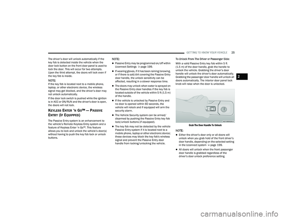
handle from locking/unlocking the vehicle. To Unlock From The Driver or Passenger Side:
With a valid Passive Entry key fob within 5 ft
(1.5 m) of the door handle, grab the handle to
unlock the vehicle. Grabbing the driver’s door
handle will unlock the driver’s door automatically.
Grabbing the passenger door handle will unlock all
doors automatically. The interior door panel lock
knob will raise when the door is unlocked.
Grab The Door Handle To Unlock
NOTE:
Either the driver’s door only or all doors will
unlock when you grab hold of the front driver’s
door handle, depending on the selected setting
in the Uconnect system Ú page 199.
All doors will unlock when the front passenger
door handle is grabbed regardless of the
driver’s door unlock preference setting.
2
23_DPF_OM_EN_USC_t.book Page 25
Page 39 of 444
GETTING TO KNOW YOUR VEHICLE37
Front Head Restraint Removal
Two-Way Head Restraints — If Equipped
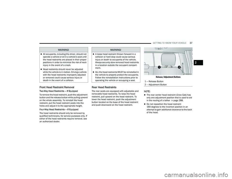
To remove the head restraint, push the adjustment
button and the release button while pulling upward
on the whole assembly. To reinstall the head
restraint, put the head restraint posts into the
holes and adjust it to the appropriate height.
Four-Way Head Restraints — If Equipped
The head restraints should only be removed by
qualified technicians, for service purposes only. If
either of the head restraints require removal, see
an authorized dealer.
Rear Head Restraints
The rear seats are equipped with adjustable and
removable head restraints. To raise the head
restraint, pull upward on the head restraint. To
lower the head restraint, push the adjustment
button located on the base of the head restraint
and push downward on the head restraint.
Release/Adjustment Buttons
NOTE:
The rear center head restraint (Crew Cab) has
only one adjustment position that is used to aid
in the routing of a tether Ú
page 288.
Do not reposition the head restraint
180 degrees to the incorrect position in an
attempt to gain additional clearance to the back
of the head.
WARNING!
All occupants, including the driver, should not
operate a vehicle or sit in a vehicle’s seat until
the head restraints are placed in their proper
positions in order to minimize the risk of neck
injury in the event of a crash.
Head restraints should never be adjusted
while the vehicle is in motion. Driving a vehicle
with the head restraints improperly adjusted
or removed could cause serious injury or
death in the event of a collision.
WARNING!
A loose head restraint thrown forward in a
collision or hard stop could cause serious
injury or death to occupants of the vehicle.
Always securely stow removed head restraints
in a location outside the occupant compart -
ment.
ALL the head restraints MUST be reinstalled in
the vehicle to properly protect the occupants.
Follow the reinstallation instructions prior to
operating the vehicle or occupying a seat.
1 — Release Button
2 — Adjustment Button
2
23_DPF_OM_EN_USC_t.book Page 37
Page 40 of 444

38GETTING TO KNOW YOUR VEHICLE
Rear Head Restraint Removal
To remove the head restraint, push the adjustment
button and the release button while pulling upward
on the whole assembly. To reinstall the head
restraint, put the head restraint posts into the
holes and adjust it to the appropriate height.
NOTE:To remove outboard restraints, the rear seat
bottom must be folded up.
DRIVER ADJUSTABLE PEDALS —
IF EQUIPPED
The adjustable pedals system is designed to allow
a greater range of driver comfort for steering wheel
tilt and seat position. This feature allows the brake
and accelerator pedals to move toward or away
from the driver to provide improved position with
the steering wheel.
The adjustable pedal switch is located to the left
side of the steering column.
Adjustable Pedals Switch
The pedals can be adjusted with the ignition in the
OFF position.
The pedals
cannot be adjusted when the vehicle is
in REVERSE or when the Cruise Control system is
on. If there is an attempt to adjust the pedals when
the system is locked out, the following messages
will appear (on vehicles equipped with an
instrument cluster display):
Adjustable Pedal Disabled — Cruise Control
Engaged
Adjustable Pedal Disabled — Vehicle In Reverse
NOTE:
Always adjust the pedals to a position that
allows full movement of the pedal.
Further small adjustments may be necessary to
find the best possible seat/pedal position.
For vehicles equipped with Driver Memory
Settings, you can use your remote keyless entry
key fob or the memory switch on the driver’s
door trim panel to return the adjustable pedals
to saved positions Ú page 30.
WARNING!
A loose head restraint thrown forward in a
collision or hard stop could cause serious
injury or death to occupants of the vehicle.
Always securely stow removed head restraints
in a location outside the occupant compart -
ment.
ALL the head restraints MUST be reinstalled in
the vehicle to properly protect the occupants.
Follow the reinstallation instructions prior to
operating the vehicle or occupying a seat.
WARNING!
Do not adjust the pedals while the vehicle is
moving. You could lose control and have an
accident. Always adjust the pedals while the
vehicle is parked.
23_DPF_OM_EN_USC_t.book Page 38
Page 49 of 444
GETTING TO KNOW YOUR VEHICLE47
UNIVERSAL GARAGE DOOR OPENER
(HOMELINK®) — IF EQUIPPED
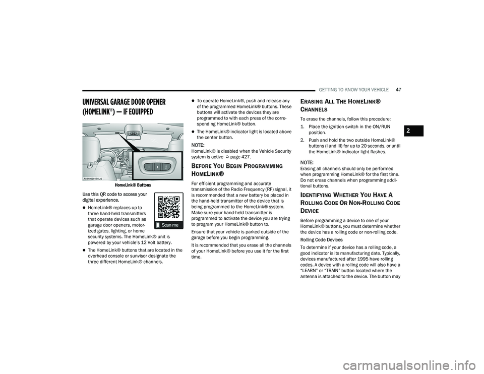
HomeLink® Buttons
Use this QR code to access your
digital experience.
HomeLink® replaces up to
three hand-held transmitters
that operate devices such as
garage door openers, motor -
ized gates, lighting, or home
security systems. The HomeLink® unit is
powered by your vehicle’s 12 Volt battery.
The HomeLink® buttons that are located in the
overhead console or sunvisor designate the
three different HomeLink® channels.
To operate HomeLink®, push and release any
of the programmed HomeLink® buttons. These
buttons will activate the devices they are
programmed to with each press of the corre -
sponding HomeLink® button.
The HomeLink® indicator light is located above
the center button.
NOTE:HomeLink® is disabled when the Vehicle Security
system is active Ú page 427.
BEFORE YOU BEGIN PROGRAMMING
H
OMELINK®
For efficient programming and accurate
transmission of the Radio Frequency (RF) signal, it
is recommended that a new battery be placed in
the hand-held transmitter of the device that is
being programmed to the HomeLink® system.
Make sure your hand-held transmitter is
programmed to activate the device you are trying
to program your HomeLink® button to.
Ensure that your vehicle is parked outside of the
garage before you begin programming.
It is recommended that you erase all the channels
of your HomeLink® before you use it for the first
time.
ERASING ALL THE HOMELINK®
C
HANNELS
To erase the channels, follow this procedure:
1. Place the ignition switch in the ON/RUN
position.
2. Push and hold the two outside HomeLink® buttons (I and III) for up to 20 seconds, or until
the HomeLink® indicator light flashes.
NOTE:Erasing all channels should only be performed
when programming HomeLink® for the first time.
Do not erase channels when programming addi -
tional buttons.
IDENTIFYING WHETHER YOU HAVE A
R
OLLING CODE OR NON-ROLLING CODE
D
EVICE
Before programming a device to one of your
HomeLink® buttons, you must determine whether
the device has a rolling code or non-rolling code.
Rolling Code Devices
To determine if your device has a rolling code, a
good indicator is its manufacturing date. Typically,
devices manufactured after 1995 have rolling
codes. A device with a rolling code will also have a
“LEARN” or “TRAIN” button located where the
antenna is attached to the device. The button may
2
23_DPF_OM_EN_USC_t.book Page 47
Page 52 of 444
50GETTING TO KNOW YOUR VEHICLE
NOTE:
If the indicator light stays on constantly,
programming is complete and the garage
door/device should activate when the
HomeLink® button is pushed.
To program the two remaining HomeLink®
buttons, repeat each step for each
remaining button. DO NOT erase the chan -
nels.
If you unplugged the garage door opener/device
for programming, plug it back in at this time.
Reprogramming A Single HomeLink® Button
(Canadian/Gate Operator)
To reprogram a channel that has been previously
trained, follow these steps:
1. Place the ignition in the ON/RUN position.
2. Press and hold the desired HomeLink® button until the indicator light begins to flash after 20
seconds. Do not release the button.
3. Without releasing the button, proceed with “Canadian/Gate Operator Programming” Step
2 and follow all remaining steps.
SECURITY
It is advised to erase all channels before you sell or
turn in your vehicle.
To do this, push and hold the two outside buttons
for 20 seconds until the indicator flashes. Note
that all channels will be erased. Individual
channels cannot be erased.
The HomeLink® Universal Transceiver is disabled
when the Vehicle Security system is active.
TROUBLESHOOTING TIPS
If you are having trouble programming
HomeLink®, here are some of the most common
solutions:
Replace the battery in the garage door opener
hand-held transmitter.
Push the LEARN button on the garage door
opener to complete the training for a rolling
code.
Did you unplug the device for programming and
remember to plug it back in?
If you have any problems, or require assistance,
please call toll-free 1-800-355-3515 or on the
Internet at
HomeLink.com for information or
assistance.
WARNING!
Vehicle exhaust contains carbon monoxide, a
dangerous gas. Do not run your vehicle in the
garage while programming the transmitter.
Exhaust gas can cause serious injury or death.
Your motorized door or gate will open and
close while you are programming the universal
transmitter. Do not program the transmitter if
people, pets or other objects are in the path of
the door or gate. Only use this transmitter with
a garage door opener that has a “stop and
reverse” feature as required by Federal safety
standards. This includes most garage door
opener models manufactured after 1982. Do
not use a garage door opener without these
safety features.
23_DPF_OM_EN_USC_t.book Page 50
Page 71 of 444

GETTING TO KNOW YOUR VEHICLE69
Unfolding The Load Floor/Crew Cab
1. Lift the 60/40 seat cushion(s) to the upward position.
Load Floor Legs In Stowed Position
2. Unfold both the legs using the straps.
Load Floor Legs In Opened Position
3. Lift the front panel until the load floor unfolds
into position.
Load Floor In Open Position
4. Reverse the procedure to store the load floor.
Positioning The Load Floor For Storage Access
Under The Seat
1. Lift the 60/40 seat cushion(s) to the upward position.
2. Unsnap the securing snap located at either side of the load floor.
3. Lift the load floor up to access storage under the load floor.
Load Floor Securing Straps/Crew Cab
4. Reverse the procedure to put the load floor back in the secured down position before you
operate the vehicle.
WARNING!
Do not drive with the load floor in the up
position. When stopping fast or in an accident,
the load floor could move to the down position
causing serious injury.
2
23_DPF_OM_EN_USC_t.book Page 69
Page 72 of 444
70GETTING TO KNOW YOUR VEHICLE
Below Rear Seat Storage (Crew Cab)
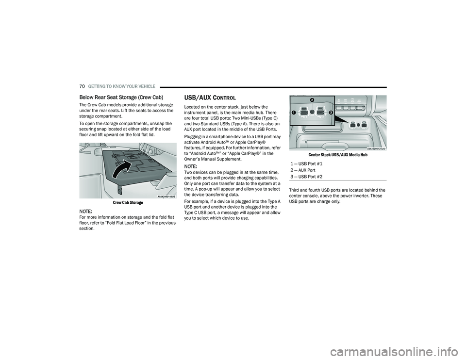
The Crew Cab models provide additional storage
under the rear seats. Lift the seats to access the
storage compartment.
To open the storage compartments, unsnap the
securing snap located at either side of the load
floor and lift upward on the fold flat lid.
Crew Cab Storage
NOTE:For more information on storage and the fold flat
floor, refer to “Fold Flat Load Floor” in the previous
section.
USB/AUX CONTROL
Located on the center stack, just below the
instrument panel, is the main media hub. There
are four total USB ports: Two Mini-USBs (Type C)
and two Standard USBs (Type A). There is also an
AUX port located in the middle of the USB Ports.
Plugging in a smartphone device to a USB port may
activate Android Auto™ or Apple CarPlay®
features, if equipped. For further information, refer
to “Android Auto™” or “Apple CarPlay®” in the
Owner’s Manual Supplement.
NOTE:Two devices can be plugged in at the same time,
and both ports will provide charging capabilities.
Only one port can transfer data to the system at a
time. A pop-up will appear and allow you to select
the device transferring data.
For example, if a device is plugged into the Type A
USB port and another device is plugged into the
Type C USB port, a message will appear and allow
you to select which device to use.
Center Stack USB/AUX Media Hub
Third and fourth USB ports are located behind the
center console, above the power inverter. These
USB ports are charge only.
1 — USB Port #1
2 — AUX Port
3 — USB Port #2
23_DPF_OM_EN_USC_t.book Page 70
Page 103 of 444

GETTING TO KNOW YOUR INSTRUMENT PANEL101
drive to the nearest authorized dealer and have
your vehicle serviced as soon as possible.
5 MPH Max Speed in 150 mi Service DEF
System See Dealer — This message will display
if the DEF system has not been serviced after
the “Service DEF System – See Dealer”
message is displayed. This message will contin -
uously display until the mileage counter reaches
zero, and will be accompanied by a periodic
chime. The message will continue to countdown
until it reaches zero unless the vehicle is
serviced. We recommend you drive to your
nearest authorized dealer and have your vehicle
serviced immediately.
NOTE:Under some circumstances this mileage counter
may start with a value of less than 150 miles
(241 km). For example, if recurring faults are
detected in a time interval of less than 40 hours,
the counter may restart at the value where it
stopped when a previous fault was temporarily
remedied, or at a minimum of 50 miles (80 km).
5 MPH Max Speed on Restart, Long Idle or
Refuel Service DEF See Dealer — This message
will continuously display when the mileage
counter reaches zero, and will be accompanied
by a periodic chime. The vehicle will only be capable of a maximum
speed of 5 mph upon the first of the following
conditions to occur:
If the vehicle is shutoff and restarted.
If the vehicle is idled for an extended period
of time, approximately one hour or greater.
If the system detects that the level of fuel in
the tank has increased.
5 MPH Max Speed Service DEF System See
Dealer
— This message will continuously display,
and will be accompanied by a periodic chime.
Although the vehicle can be started and placed
in gear, the vehicle will only operate at a
maximum speed of 5 mph. Your vehicle will
require towing, see an authorized dealer for
service.
NOTE:When this message is displayed, the engine can
still be started. However, the vehicle will only
operate at a maximum speed of 5 mph.
Incorrect DEF Detected See Dealer — This
message will display when the fault is initially
detected, each time the vehicle is started, and
periodically during driving. The message will be
accompanied by a single chime. We recom -
mend you drive to the nearest authorized dealer
and have your vehicle serviced as soon as
possible.
BATTERY SAVER ON/BATTERY SAVER
M
ODE MESSAGE — ELECTRICAL LOAD
R
EDUCTION ACTIONS — IF EQUIPPED
This vehicle is equipped with an Intelligent Battery
Sensor (IBS) to perform additional monitoring of
the electrical system and status of the vehicle
battery.
In cases when the IBS detects charging system
failure, or the vehicle battery conditions are
deteriorating, electrical load reduction actions will
take place to extend the driving time and distance
of the vehicle. This is done by reducing power to or
turning off non-essential electrical loads.
Load reduction is only active when the engine is
running. It will display a message if there is a risk
of battery depletion to the point where the vehicle
may stall due to lack of electrical supply, or will not
restart after the current drive cycle.
When load reduction is activated, the message
“Battery Saver On Some Systems May Have
Reduced Power” will appear in the instrument
cluster.
These messages indicate the vehicle battery has a
low state of charge and continues to lose electrical
charge at a rate that the charging system cannot
sustain.
3
23_DPF_OM_EN_USC_t.book Page 101