turn signal RAM CHASSIS CAB 2023 Owner's Manual
[x] Cancel search | Manufacturer: RAM, Model Year: 2023, Model line: CHASSIS CAB, Model: RAM CHASSIS CAB 2023Pages: 444, PDF Size: 20.51 MB
Page 174 of 444
172STARTING AND OPERATING
Deactivation
The Forward Facing Camera is deactivated in the
following conditions:
The vehicle exceeds 8 mph (13 km/h), except
when vehicle is in 4WD Low
The touchscreen X button on the display is
pressed.
The vehicle is shifted into PARK.
The ignition is placed in the OFF position.
NOTE:If the vehicle is in 4WD Low, the Forward Facing
Camera image will be displayed until the X button
is pressed or the ignition is placed in the OFF
position.
Trailer Reverse Guidance — If Equipped
The Trailer Reverse Guidance feature assists the
driver in backing up a trailer by providing
adjustable camera views of the trailer and
surrounding area. The cameras are mounted on
the side mirrors and the images will be displayed
side-by-side on the touchscreen. Left and right
camera images are swapped and mirrored on the
touchscreen to show the equivalent area behind
the vehicle as though the driver is using the side
mirrors. Activation
The Trailer Reverse Guidance feature can be
activated by pressing the Trailer Reverse Guidance
button on the Back Up/Cargo Camera Display.
Deactivation
When the vehicle is shifted out of REVERSE with
camera delay turned on, the camera image will
continue to be displayed for up to 10 seconds unless
the vehicle speed exceeds 8 mph (13 km/h), the
vehicle is shifted into PARK or the ignition is placed
in the OFF position. There is a touchscreen X button
to disable the display of the camera image.
If Trailer Reverse Guidance is selected through
manually activated Surround View, Back Up
Camera, or Cargo Camera, the following
deactivation conditions apply:
The touchscreen X button on the display is
pressed
The ignition is placed in the OFF position
The vehicle speed is over 8 mph (13 km/h) for
10 seconds
Blind Spot Assist Cameras — If Equipped
There are cameras located in the exterior mirrors
to assist in blind spot detection by providing a wide
camera view of the side of the vehicle selected.
The blind spot cameras will work in the ON/RUN or
ignition ON position. Press the X or More Cams
button to exit the screen. The Blind Spot Cameras can also be activated with Turn Signal
engagement, see Ú
page 166 for more
information.
Activation
Press the Driver Blind Spot or Passenger Blind
Spot buttons by locating the Vehicle screen, then
Cameras screen.
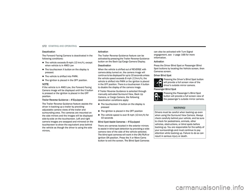
Driver Blind Spot
Pressing the Driver’s Blind Spot button
will provide a full screen view of the
driver’s outside mirror camera.
Passenger Blind Spot Pressing the Passenger’s Blind Spot
button will provide a full screen view of
the passenger’s outside mirror camera.
WARNING!
Drivers must be careful when backing up even
when using the Surround View Camera. Always
check carefully behind your vehicle, and be sure
to check for pedestrians, animals, other
vehicles, obstructions, or blind spots before
backing up. You are responsible for the safety of
your surroundings and must continue to pay
attention while backing up. Failure to do so can
result in serious injury or death.
23_DPF_OM_EN_USC_t.book Page 172
Page 192 of 444
190STARTING AND OPERATING
Display Messages
The trailer brake control interacts with the
instrument cluster display. Display messages,
along with a single chime, will be displayed when a
malfunction is determined in the trailer
connection, trailer brake control, or on the trailer
Ú page 89.
NOTE:
An aftermarket controller may be available for
use with trailers with air or EOH trailer brake
systems. To determine the type of brakes on
your trailer and the availability of controllers,
check with your trailer manufacturer or dealer.
Removal of the ITBM will cause errors and it
may cause damage to the electrical system and
electronic modules of the vehicle. See an autho -
rized dealer if an aftermarket module is to be
installed.
Towing Requirements — Trailer Lights And
Wiring
Whenever you pull a trailer, regardless of the trailer
size, stoplights and turn signals on the trailer are
required for motoring safety.
The Trailer Tow Package may include a four- and
seven-pin wiring harness. Use a factory approved
trailer harness and connector.
NOTE:Do not cut or splice wiring into the vehicle’s wiring
harness.
The electrical connections are all complete to the
vehicle but you must mate the harness to a trailer
connector. Refer to the following illustrations.
NOTE:
Disconnect the trailer wiring connector from the
vehicle (or any other device plugged into
vehicle’s electrical connectors) before
launching a boat into water.
Be sure to reconnect once clear from water
area.
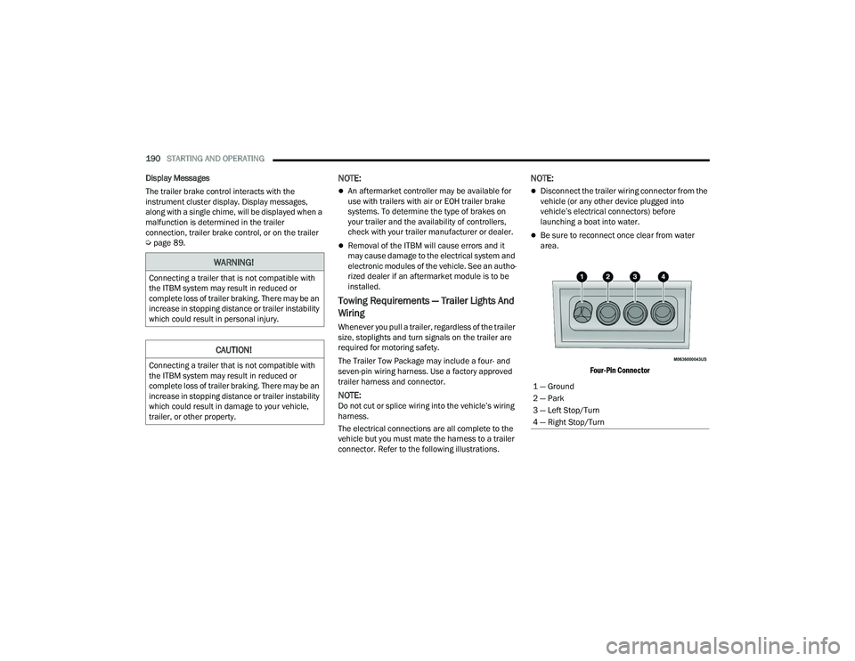
Four-Pin Connector
WARNING!
Connecting a trailer that is not compatible with
the ITBM system may result in reduced or
complete loss of trailer braking. There may be an
increase in stopping distance or trailer instability
which could result in personal injury.
CAUTION!
Connecting a trailer that is not compatible with
the ITBM system may result in reduced or
complete loss of trailer braking. There may be an
increase in stopping distance or trailer instability
which could result in damage to your vehicle,
trailer, or other property.
1 — Ground
2 — Park
3 — Left Stop/Turn
4 — Right Stop/Turn
23_DPF_OM_EN_USC_t.book Page 190
Page 193 of 444
STARTING AND OPERATING191
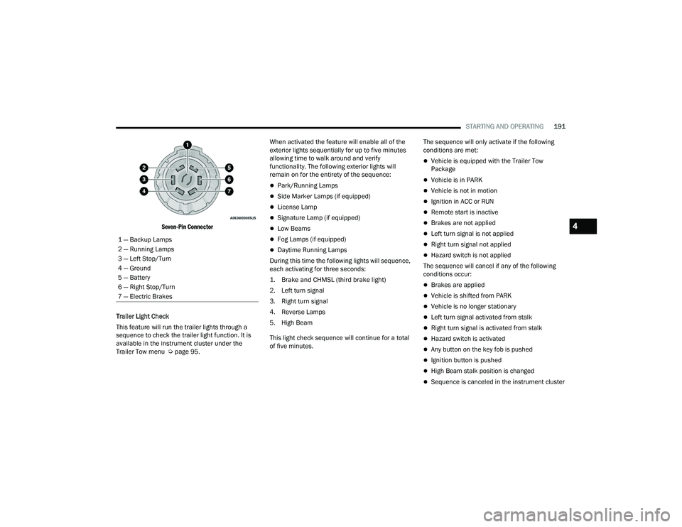
Seven-Pin Connector
Trailer Light Check
This feature will run the trailer lights through a
sequence to check the trailer light function. It is
available in the instrument cluster under the
Trailer Tow menu Ú page 95. When activated the feature will enable all of the
exterior lights sequentially for up to five minutes
allowing time to walk around and verify
functionality. The following exterior lights will
remain on for the entirety of the sequence:
Park/Running Lamps
Side Marker Lamps (if equipped)
License Lamp
Signature Lamp (if equipped)
Low Beams
Fog Lamps (if equipped)
Daytime Running Lamps
During this time the following lights will sequence,
each activating for three seconds:
1. Brake and CHMSL (third brake light)
2. Left turn signal
3. Right turn signal
4. Reverse Lamps
5. High Beam
This light check sequence will continue for a total
of five minutes. The sequence will only activate if the following
conditions are met:
Vehicle is equipped with the Trailer Tow
Package
Vehicle is in PARK
Vehicle is not in motion
Ignition in ACC or RUN
Remote start is inactive
Brakes are not applied
Left turn signal is not applied
Right turn signal not applied
Hazard switch is not applied
The sequence will cancel if any of the following
conditions occur:
Brakes are applied
Vehicle is shifted from PARK
Vehicle is no longer stationary
Left turn signal activated from stalk
Right turn signal is activated from stalk
Hazard switch is activated
Any button on the key fob is pushed
Ignition button is pushed
High Beam stalk position is changed
Sequence is canceled in the instrument cluster
1 — Backup Lamps
2 — Running Lamps
3 — Left Stop/Turn
4 — Ground
5 — Battery
6 — Right Stop/Turn
7 — Electric Brakes
4
23_DPF_OM_EN_USC_t.book Page 191
Page 208 of 444
206MULTIMEDIA
Safety/Driving Assistance
When the Safety/Driving Assistance button is selected on the touchscreen, the system displays the options related to the vehicle’s safety settings. These
options will differ depending on the features equipped on the vehicle. The settings may display in list form or within subfolders on the screen. To access a
subfolder, select the desired folder; the available options related to that feature will then display on the screen.
NOTE:Depending on the vehicle’s options, feature settings may vary.
Setting Name Description
Forward Collision Warning Sensitivity This setting will change the distance at which the Forward Collision Warning
(FCW) alert sounds. The “Medium” setting will have the FCW system signal
when an object is in view, and the possibility of a collision is detected. The
“Near” setting will have the FCW system signal when the object is closer to the
vehicle. The “Far” setting will have the FCW system signal when an object is at
a far distance from the vehicle.
Forward Collision Warning This setting will turn the Forward Collision Warning system on or off. The “Off”
setting will deactivate the FCW system. The “Warning Only” setting will provide
only an audible chime when a collision is detected. The “Warning + Active
Braking” setting will provide an audible chime and apply some brake pressure
when a collision is detected.
Pedestrian Emergency Braking This setting will turn the Pedestrian Emergency Braking system on or off.
LaneSense Warning
This setting will change the distance at which the steering wheel will provide lane
departure feedback. The available settings are “Early”, “Medium”, and “Late”.
LaneSense Strength This setting will change the strength of the steering wheel feedback during a
lane departure. The available settings are “Low”, “Medium”, and “High”.
23_DPF_OM_EN_USC_t.book Page 206
Page 213 of 444
MULTIMEDIA211
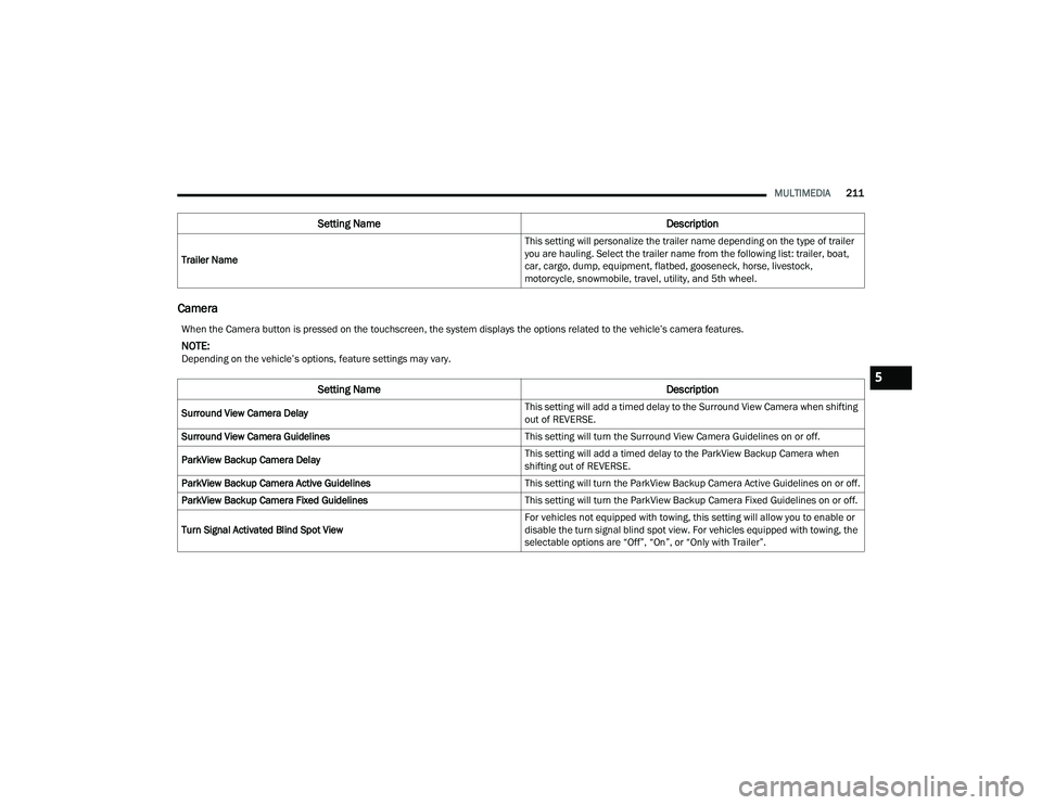
Camera
Trailer Name This setting will personalize the trailer name depending on the type of trailer
you are hauling. Select the trailer name from the following list: trailer, boat,
car, cargo, dump, equipment, flatbed, gooseneck, horse, livestock,
motorcycle, snowmobile, travel, utility, and 5th wheel.
Setting Name
Description
When the Camera button is pressed on the touchscreen, the system displays the options related to the vehicle’s camera features.
NOTE:Depending on the vehicle’s options, feature settings may vary.
Setting NameDescription
Surround View Camera Delay This setting will add a timed delay to the Surround View Camera when shifting
out of REVERSE.
Surround View Camera Guidelines This setting will turn the Surround View Camera Guidelines on or off.
ParkView Backup Camera Delay This setting will add a timed delay to the ParkView Backup Camera when
shifting out of REVERSE.
ParkView Backup Camera Active Guidelines This setting will turn the ParkView Backup Camera Active Guidelines on or off.
ParkView Backup Camera Fixed Guidelines This setting will turn the ParkView Backup Camera Fixed Guidelines on or off.
Turn Signal Activated Blind Spot View For vehicles not equipped with towing, this setting will allow you to enable or
disable the turn signal blind spot view. For vehicles equipped with towing, the
selectable options are “Off”, “On”, or “Only with Trailer”.
5
23_DPF_OM_EN_USC_t.book Page 211
Page 235 of 444
MULTIMEDIA233
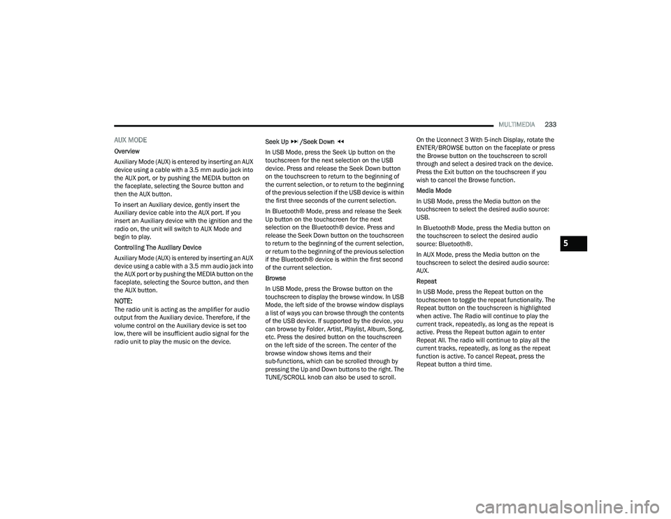
AUX MODE
Overview
Auxiliary Mode (AUX) is entered by inserting an AUX
device using a cable with a 3.5 mm audio jack into
the AUX port, or by pushing the MEDIA button on
the faceplate, selecting the Source button and
then the AUX button.
To insert an Auxiliary device, gently insert the
Auxiliary device cable into the AUX port. If you
insert an Auxiliary device with the ignition and the
radio on, the unit will switch to AUX Mode and
begin to play.
Controlling The Auxiliary Device
Auxiliary Mode (AUX) is entered by inserting an AUX
device using a cable with a 3.5 mm audio jack into
the AUX port or by pushing the MEDIA button on the
faceplate, selecting the Source button, and then
the AUX button.
NOTE:The radio unit is acting as the amplifier for audio
output from the Auxiliary device. Therefore, if the
volume control on the Auxiliary device is set too
low, there will be insufficient audio signal for the
radio unit to play the music on the device. Seek Up
/Seek Down
In USB Mode, press the Seek Up button on the
touchscreen for the next selection on the USB
device. Press and release the Seek Down button
on the touchscreen to return to the beginning of
the current selection, or to return to the beginning
of the previous selection if the USB device is within
the first three seconds of the current selection.
In Bluetooth® Mode, press and release the Seek
Up button on the touchscreen for the next
selection on the Bluetooth® device. Press and
release the Seek Down button on the touchscreen
to return to the beginning of the current selection,
or return to the beginning of the previous selection
if the Bluetooth® device is within the first second
of the current selection.
Browse
In USB Mode, press the Browse button on the
touchscreen to display the browse window. In USB
Mode, the left side of the browse window displays
a list of ways you can browse through the contents
of the USB device. If supported by the device, you
can browse by Folder, Artist, Playlist, Album, Song,
etc. Press the desired button on the touchscreen
on the left side of the screen. The center of the
browse window shows items and their
sub-functions, which can be scrolled through by
pressing the Up and Down buttons to the right. The
TUNE/SCROLL knob can also be used to scroll. On the Uconnect 3 With 5-inch Display, rotate the
ENTER/BROWSE button on the faceplate or press
the Browse button on the touchscreen to scroll
through and select a desired track on the device.
Press the Exit button on the touchscreen if you
wish to cancel the Browse function.
Media Mode
In USB Mode, press the Media button on the
touchscreen to select the desired audio source:
USB.
In Bluetooth® Mode, press the Media button on
the touchscreen to select the desired audio
source: Bluetooth®.
In AUX Mode, press the Media button on the
touchscreen to select the desired audio source:
AUX.
Repeat
In USB Mode, press the Repeat button on the
touchscreen to toggle the repeat functionality. The
Repeat button on the touchscreen is highlighted
when active. The Radio will continue to play the
current track, repeatedly, as long as the repeat is
active. Press the Repeat button again to enter
Repeat All. The radio will continue to play all the
current tracks, repeatedly, as long as the repeat
function is active. To cancel Repeat, press the
Repeat button a third time.
5
23_DPF_OM_EN_USC_t.book Page 233
Page 237 of 444
MULTIMEDIA235
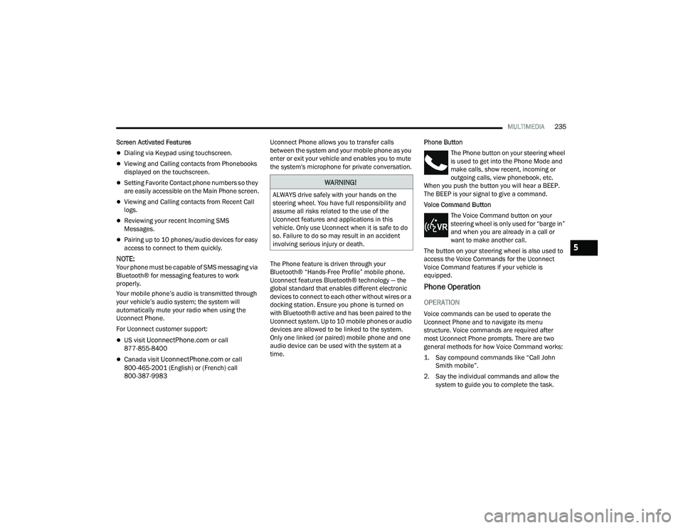
Screen Activated Features
Dialing via Keypad using touchscreen.
Viewing and Calling contacts from Phonebooks
displayed on the touchscreen.
Setting Favorite Contact phone numbers so they
are easily accessible on the Main Phone screen.
Viewing and Calling contacts from Recent Call
logs.
Reviewing your recent Incoming SMS
Messages.
Pairing up to 10 phones/audio devices for easy
access to connect to them quickly.
NOTE:Your phone must be capable of SMS messaging via
Bluetooth® for messaging features to work
properly.
Your mobile phone’s audio is transmitted through
your vehicle’s audio system; the system will
automatically mute your radio when using the
Uconnect Phone.
For Uconnect customer support:
US visit UconnectPhone.com or call
877-855-8400
Canada visit UconnectPhone.com or call
800-465-2001 (English) or (French) call
800-387-9983 Uconnect Phone allows you to transfer calls
between the system and your mobile phone as you
enter or exit your vehicle and enables you to mute
the system's microphone for private conversation.
The Phone feature is driven through your
Bluetooth® “Hands-Free Profile” mobile phone.
Uconnect features Bluetooth® technology — the
global standard that enables different electronic
devices to connect to each other without wires or a
docking station. Ensure you phone is turned on
with Bluetooth® active and has been paired to the
Uconnect system. Up to 10 mobile phones or audio
devices are allowed to be linked to the system.
Only one linked (or paired) mobile phone and one
audio device can be used with the system at a
time.
Phone Button
The Phone button on your steering wheel
is used to get into the Phone Mode and
make calls, show recent, incoming or
outgoing calls, view phonebook, etc.
When you push the button you will hear a BEEP.
The BEEP is your signal to give a command.
Voice Command Button
The Voice Command button on your
steering wheel is only used for “barge in”
and when you are already in a call or
want to make another call.
The button on your steering wheel is also used to
access the Voice Commands for the Uconnect
Voice Command features if your vehicle is
equipped.
Phone Operation
OPERATION
Voice commands can be used to operate the
Uconnect Phone and to navigate its menu
structure. Voice commands are required after
most Uconnect Phone prompts. There are two
general methods for how Voice Command works:
1. Say compound commands like “Call John Smith mobile”.
2. Say the individual commands and allow the system to guide you to complete the task.
WARNING!
ALWAYS drive safely with your hands on the
steering wheel. You have full responsibility and
assume all risks related to the use of the
Uconnect features and applications in this
vehicle. Only use Uconnect when it is safe to do
so. Failure to do so may result in an accident
involving serious injury or death.
5
23_DPF_OM_EN_USC_t.book Page 235
Page 250 of 444
248MULTIMEDIA
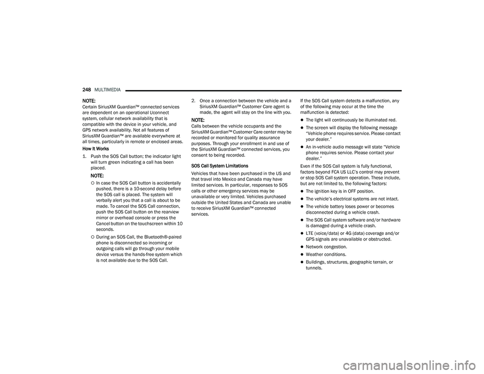
NOTE:Certain SiriusXM Guardian™ connected services
are dependent on an operational Uconnect
system, cellular network availability that is
compatible with the device in your vehicle, and
GPS network availability. Not all features of
SiriusXM Guardian™ are available everywhere at
all times, particularly in remote or enclosed areas.
How It Works
1. Push the SOS Call button; the indicator light will turn green indicating a call has been
placed.
NOTE:
In case the SOS Call button is accidentally
pushed, there is a 10-second delay before
the SOS call is placed. The system will
verbally alert you that a call is about to be
made. To cancel the SOS Call connection,
push the SOS Call button on the rearview
mirror or overhead console or press the
Cancel button on the touchscreen within 10
seconds.
During an SOS Call, the Bluetooth®-paired
phone is disconnected so incoming or
outgoing calls will go through your mobile
device versus the hands-free system which
is not available due to the SOS Call. 2. Once a connection between the vehicle and a
SiriusXM Guardian™ Customer Care agent is
made, the agent will stay on the line with you.
NOTE:Calls between the vehicle occupants and the
SiriusXM Guardian™ Customer Care center may be
recorded or monitored for quality assurance
purposes. Through your enrollment in and use of
the SiriusXM Guardian™ connected services, you
consent to being recorded.
SOS Call System Limitations
Vehicles that have been purchased in the US and
that travel into Mexico and Canada may have
limited services. In particular, responses to SOS
calls or other emergency services may be
unavailable or very limited. Vehicles purchased
outside the United States and Canada are unable
to receive SiriusXM Guardian™ connected
services. If the SOS Call system detects a malfunction, any
of the following may occur at the time the
malfunction is detected:The light will continuously be illuminated red.
The screen will display the following message
“Vehicle phone requires service. Please contact
your dealer.”
An in-vehicle audio message will state “Vehicle
phone requires service. Please contact your
dealer.”
Even if the SOS Call system is fully functional,
factors beyond FCA US LLC’s control may prevent
or stop SOS Call system operation. These include,
but are not limited to, the following factors:
The ignition key is in OFF position.
The vehicle’s electrical systems are not intact.
The vehicle battery loses power or becomes
disconnected during a vehicle crash.
The SOS Call system software and/or hardware
is damaged during a vehicle crash.
LTE (voice/data) or 4G (data) coverage and/or
GPS signals are unavailable or obstructed.
Network congestion.
Weather conditions.
Buildings, structures, geographic terrain, or
tunnels.
23_DPF_OM_EN_USC_t.book Page 248
Page 251 of 444
MULTIMEDIA249
(Continued)
(Continued)
If your vehicle loses battery power for any reason
(including during or after an accident), the SOS Call
system, among other vehicle systems, will not
operate.
Requirements
This feature is available only on vehicles sold in
the US or Canada.
Vehicle must be properly equipped with the Siri
-
usXM Guardian™ connected services. Vehicle
must be registered with SiriusXM Guardian™
and have an active subscription that includes
the applicable feature.
Vehicle must have an operable LTE (voice/data)
or 4G (data) network connection compatible
with your device.
Vehicle must be powered in the ON/RUN or ACC
(Accessory) position with a properly functioning
electrical system.
Automatic SOS — If Equipped
Automatic SOS is a hands-free safety service that
can immediately connect you with help in the event
that your vehicle’s airbags deploy. After an
accident, a live agent will contact you through the
Uconnect system and alert emergency services.
NOTE:An active SiriusXM Guardian™ subscription is
required for this feature to function.
WARNING!
Never place anything on or near the vehicle’s
LTE (voice/data) or 4G (data) and GPS
antennas. You could prevent LTE (voice/data)
or 4G (data) and GPS signal reception, which
can prevent your vehicle from placing an
emergency call.
Do not add any aftermarket electrical equip -
ment to the vehicle’s electrical system. This
may prevent your vehicle from sending a
signal to initiate an emergency call. To avoid
interference that can cause the SOS Call
system to fail, never add aftermarket equip -
ment (e.g., two-way mobile radio, CB radio,
data recorder, etc.) to your vehicle’s electrical
system or modify the antennas on your
vehicle. IF YOUR VEHICLE LOSES POWER FOR
ANY REASON (INCLUDING DURING OR AFTER
AN ACCIDENT), NEITHER THE VEHICLE
BRANDED APPS NOR THE SIRIUSXM
GUARDIAN™ CONNECTED SERVICES WILL
OPERATE.
The Occupant Restraint Controller (ORC) turns
on the Air Bag Warning Light on the instru -
ment panel if a malfunction in any part of the
air bag system is detected. If the Air Bag
Warning Light is illuminated, the air bag
system may not be working properly and the
SOS Call system may not be able to send a
signal to the SiriusXM Guardian™ Customer
Care center. If the Air Bag Warning Light is illu -
minated, have an authorized dealer service
your vehicle immediately.
WARNING!
Ignoring the Rearview Mirror Light could mean
you will not have SOS Call services if needed.
If the Rearview Mirror Light is illuminated,
have an authorized dealer service the SOS
Call system immediately.
If anyone in the vehicle could be in danger
(e.g., fire or smoke is visible, dangerous road
conditions or location), do not wait for voice
contact from a SiriusXM Guardian™
Customer Care agent. All occupants should
exit the vehicle immediately and move to a
safe location.
Failure to perform scheduled maintenance
and regular inspection of your vehicle may
result in vehicle damage, accident or injury.
WARNING!
5
23_DPF_OM_EN_USC_t.book Page 249
Page 279 of 444

SAFETY277
Towing With HSA
HSA will also provide assistance to mitigate roll
back while towing a trailer.
Ready Alert Braking (RAB)
RAB may reduce the time required to reach full
braking during emergency braking situations. It
anticipates when an emergency braking situation
may occur by monitoring how fast the throttle is
released by the driver. The Electronic Brake
Control system will prepare the brake system for a
panic stop.
Traction Control System (TCS)
The TCS monitors the amount of wheel spin of
each of the driven wheels. If wheel spin is
detected, the TCS may apply brake pressure to the
spinning wheel(s) and/or reduce engine power to
provide enhanced acceleration and stability. A
feature of the TCS, Brake Limited Differential (BLD)
functions similarly to a limited slip differential and
controls the wheel spin across a driven axle. If one
wheel on a driven axle is spinning faster than the
other, the system will apply the brake of the
spinning wheel. This will allow more engine power
to be applied to the wheel that is not spinning. BLD
may remain enabled even if TCS and Electronic
Stability Control (ESC) are in reduced modes.
Trailer Sway Control (TSC)
TSC uses sensors in the vehicle to recognize an
excessively swaying trailer and will take the
appropriate actions to attempt to stop the sway.
NOTE:TSC cannot stop all trailers from swaying. Always
use caution when towing a trailer and follow the
trailer tongue weight recommendations
Úpage 181. When TSC is functioning, the ESC Activation/
Malfunction Indicator Light will flash, the engine
power may be reduced and you may feel the
brakes being applied to individual wheels to
attempt to stop the trailer from swaying. TSC is
disabled when the ESC system is in the “Partial
Off” or “Full Off” modes.
AUXILIARY DRIVING SYSTEMS
BLIND SPOT ASSIST CAMERAS —
I
F EQUIPPED
Blind Spot Assist Cameras
There are cameras located in the exterior mirrors
to assist in blind spot detection. Refer to
Ú page 166 to learn more about how the cameras
function with turn signal engagement or refer to
Ú page 168 to learn how to activate the cameras
through the Camera's screen.
WARNING!
If you use a trailer brake controller with your
trailer, the trailer brakes may be activated and
deactivated with the brake switch. If so, there
may not be enough brake pressure to hold
both the vehicle and the trailer on a hill when
the brake pedal is released. In order to avoid
rolling down an incline while resuming accel -
eration, manually activate the trailer brake or
apply more vehicle brake pressure prior to
releasing the brake pedal.
HSA is not a parking brake. Always apply the
parking brake fully when exiting your vehicle. Also,
be certain to place the transmission in PARK.
Failure to follow these warnings can result in a
collision or serious personal injury.
WARNING!
If TSC activates while driving, slow the vehicle
down, stop at the nearest safe location, and
adjust the trailer load to eliminate trailer sway.
6
23_DPF_OM_EN_USC_t.book Page 277