ECO mode RAM CHASSIS CAB 2023 Service Manual
[x] Cancel search | Manufacturer: RAM, Model Year: 2023, Model line: CHASSIS CAB, Model: RAM CHASSIS CAB 2023Pages: 444, PDF Size: 20.51 MB
Page 176 of 444
174STARTING AND OPERATING
Inputting Trailer Values
For the Trailer Surround View Camera system to
function, all fields must be entered. When a value
is needed the screen will display “Required”.
When the Trailer Type button is selected two
options are available: Conventional or Gooseneck/
5th Wheel.
Activation
The Trailer Surround Camera can be activated
through the Uconnect system when the vehicle is
in PARK, NEUTRAL, or DRIVE.
When the vehicle is shifted into REVERSE,
Surround View Camera showing the Top View and
Back Up Camera is the default view of the system.
Press the More Cams button and then press the
Trailer tab to access the Trailer Cameras. Press Trailer Surround Camera button to access Top
View and Rear View of the trailer.
If the camera delay is turned on, the camera image
will display for up to 10 seconds after shifting out
of REVERSE. The camera image will not display for
10 seconds if the vehicle speed exceeds 8 mph
(13 km/h), the vehicle is shifted into PARK, or the
ignition is placed in the OFF position. The
touchscreen X button disables the display of the
camera image.
If the camera delay is turned off, the camera image
will close and display the previous screen after
shifting out of REVERSE.
Modes Of Operation
The Trailer Surround View Camera system offers
two different camera displays:
Top View split screen with one selected
mounted camera
Full screen view of a selected mounted camera
Press the More Cams button on the Surround View
screen and select the Trailer tab to access the
Trailer Cameras. Press Trailer Surround Camera
button to access the default Top View and Rear
View of the trailer.
Top View
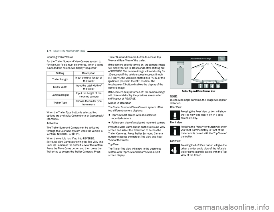
The Trailer Top View will show in the Uconnect
system with Top View and Rear View in a split
screen display.
Trailer Top and Rear Camera View
NOTE:Due to wide angle cameras, the image will appear
distorted.
Rear View
Pressing the Rear View button will show
the Top View and Rear View in a split
screen display.
Front View Pressing the Front View button will show
you what is immediately in front of the
trailer and is paired with the Top View of
the trailer.
Left View Pressing the Left View button will give the
driver a wider angle view of the left side
trailer camera and is paired with the Top
View of the trailer.
Setting
Description
Trailer Length Input the total length of
the trailer
Trailer Width Input the total width of
the trailer
Camera Height Input the height of the
mounted camera
Trailer Type Choose the trailer type
from menu
23_DPF_OM_EN_USC_t.book Page 174
Page 177 of 444
STARTING AND OPERATING175
Right View Pressing the Right View button will give
the driver a wider angle view of the right
side trailer camera and is paired with the
Top View of the trailer.
Full Screen Camera View
To display a full screen image of the Trailer
Surround View mounted cameras, select one of
the following options from the Trailer Cameras
screen: Trailer Left, Trailer Right, Trailer Front,
Trailer Rear. Exiting out of the full screen view will
return the system to the previous screen.
NOTE:If the Trailer Surround Camera was selected
through the More Cameras menu, an option to
return to the More Cameras menu will display. If
the Trailer Surround Camera was manually acti-
vated through the Controls menu of the Uconnect
system, exiting out of the display screen will return
to the Controls menu.
Trailer Reverse Guidance Pressing the Trailer Reverse Guidance
button will provide a split screen view of
the cargo area and trailer, and provides
the option to pan left or right. For more
information, see Ú page 168. Deactivation
The system is deactivated in the following
conditions if it was activated
automatically:
When the vehicle is shifted out of REVERSE with
camera delay turned on, the camera image will
continue to be displayed for up to 10 seconds,
unless the vehicle speed exceeds 8 mph
(13 km/h), the vehicle is shifted into PARK or
the ignition is placed in the OFF position. There
is a touchscreen X button to disable the display
of the camera image.
When the vehicle is shifted out of REVERSE with
camera delay turned off, the Trailer Surround
View Camera mode is exited and the last known
screen appears again.
The system is deactivated in the following
conditions if it was activated manually from the
Uconnect controls menu via the Trailer Surround
Camera button:
The touchscreen X button on the display is
pressed
Vehicle is shifted into PARK
Ignition is placed in the OFF position
Vehicle speed is over 8 mph (13 km/h) for 10
seconds
NOTE:If the Trailer Surround Camera is activated
manually, and the vehicle is shifted into REVERSE,
deactivation methods for automatic activation are
assumed.
The camera delay system is turned off manually
through the Uconnect system Ú page 199.
NOTE:
If snow, ice, mud, or any foreign substance
builds up on the camera lenses, clean the
lenses, rinse with water, and dry with a soft
cloth. Do not cover the lenses.
If a malfunction with the system has occurred,
see an authorized dealer.
WARNING!
Drivers must be careful when backing up even
when using the Trailer Surround View Camera.
Always check carefully behind your vehicle, and
be sure to check for pedestrians, animals, other
vehicles, obstructions, or blind spots before
backing up. You are responsible for the safety of
your surroundings and must continue to pay
attention while backing up. Failure to do so can
result in serious injury or death.
4
23_DPF_OM_EN_USC_t.book Page 175
Page 181 of 444
STARTING AND OPERATING179
NOTE:When working with DEF, it is important to know
that:
Any containers or parts that come into contact
with DEF must be DEF compatible (plastic or
stainless steel). Copper, brass, aluminum, iron
or non-stainless steel should be avoided as they
are subject to corrosion by DEF.
If DEF is spilled, it should be wiped up
completely.
Adding Diesel Exhaust Fluid (DEF)
The DEF gauge (located on the instrument cluster)
will display the level of DEF remaining in the tank
Úpage 89.
NOTE:
Driving conditions (altitude, vehicle speed, load,
etc.) will effect the amount of DEF that is used in
your vehicle.
Another factor is that outside temperature can
affect DEF consumption. In cold conditions,
12°F (-11°C) and below, the DEF gauge needle
can stay on a fixed position and may not move
for extended periods of time. This is a normal
function of the system.
There is an electric heater inside the DEF tank
that automatically works when necessary. If the
DEF supply does freeze, the truck will operate
normally until it thaws.
DEF FILL PROCEDURE
NOTE:
For the correct fluid type Ú page 419.
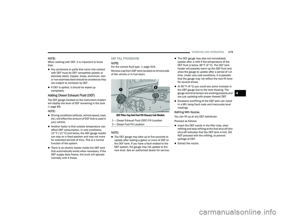
Remove cap from DEF tank (located on drivers side
of the vehicle or in fuel door).
DEF Filler Cap And Fuel Fill Chassis Cab Models
NOTE:
The DEF gauge may take up to five seconds to
update after adding a gallon or more of DEF to
the DEF tank. If you have a fault related to the
DEF system, the gauge may not update to the
new level. See an authorized dealer for service.
The DEF gauge may also not immediately
update after a refill if the temperature of the
DEF fluid is below 39°F (4°C). The DEF tank
heater will possibly warm up the DEF fluid and
allow the gauge to update after a period of run
time. Under very cold conditions, it is possible
that the gauge may not reflect the new fill level
for several drives.
At 40°F (4°C) you could see some increase in
the DEF gauge due to the tank thawing. The
gauge and level sensor are working properly and
are just updating with proper thawed DEF.
Excessive overfilling of the DEF tank can result
in a MIL lamp/fault code and inaccurate level
readings.
Refilling With Nozzles
You can fill up at any DEF distributor.
Proceed as follows:
Insert the DEF nozzle in the filler tube, start
refilling and stop refilling at the first shut-off (the
shut-off indicates that the DEF tank is full). DO
NOT proceed with the refilling, to prevent
spillage of DEF.
Extract the nozzle.
1 — Diesel Exhaust Fluid (DEF) Fill Location
2 — Diesel Fuel Fill Location
4
23_DPF_OM_EN_USC_t.book Page 179
Page 186 of 444

184STARTING AND OPERATING
3. Attach the trailer to the vehicle without the weight-distribution bars connected.
4. Measure the height from the top of the front wheel opening on the fender to the ground,
this is height H2.
5. Install and adjust the tension in the weight-distributing bars per the manufac -
turers’ recommendations so that the height of
the front fender is approximately (H2-H1)/
2+H1 (about 1/2 the difference between H2
and H1 above standard ride height [H1]).
6. Perform a visual inspection of the trailer and weight-distributing hitch to confirm manufac-
turers’ recommendations have been met.
NOTE:For all towing conditions, we recommend towing
with TOW/HAUL mode engaged.
Fifth-Wheel Hitch
The fifth-wheel hitch is a special high platform with
a coupling that mounts over the rear axle of the tow
vehicle in the truck bed. It connects a vehicle and
fifth-wheel trailer with a coupling king pin.
Your truck may be equipped with a fifth-wheel hitch
option. Refer to the separately provided fifth-wheel
hitch safety, care, assembly, and operating
instructions.
Gooseneck Hitch
The gooseneck hitch employs a pivoted coupling
arm which attaches to a ball mounted in the bed of
a pickup truck. The coupling arm connects to the
hitch mounted over the rear axle in the truck bed.
Measurement
Example Example Height (mm)
H1
1,030
H2 1,058
H2-H1 28
(H2-H1)/2 14
(H2-H1)/2 + H1 1,044
23_DPF_OM_EN_USC_t.book Page 184
Page 194 of 444

192STARTING AND OPERATING
TOWING TIPS
Before setting out on a trip, practice turning,
stopping, and backing up the trailer in an area
located away from heavy traffic.
Automatic Transmission
The DRIVE range can be selected when towing. The
transmission controls include a drive strategy to
avoid frequent shifting when towing. However, if
frequent shifting does occur while in DRIVE, select
TOW/HAUL mode or select a lower gear range (using
the Electronic Range Select (ERS) shift control).
NOTE:Using TOW/HAUL mode or selecting a lower gear
range (using the ERS shift control) while operating
the vehicle under heavy loading conditions will
improve performance and extend transmission life
by reducing excessive shifting and heat build-up.
This action will also provide better engine braking.
6-Speed Automatic Transmission Only
When towing a loaded trailer up steep grades at
low speeds (20 mph [32 km/h] or below), holding
your vehicle in FIRST gear (using the ERS shift
control) can help to avoid transmission
overheating.
If you regularly tow a trailer for more than 45 minutes
of continuous operation, then change the automatic
transmission fluid and filter(s) as specified for "police,
taxi, fleet, or frequent trailer towing."
Ú
page 344.
NOTE:Check the automatic transmission fluid level
before towing (6-speed automatic only).
Tow/Haul Mode
To reduce potential for automatic transmission
overheating, activate TOW/HAUL mode when
driving in hilly areas, or select a lower gear range
(using the Electronic Range Select (ERS) shift
control) on more severe grades.
Cruise Control — If Equipped
Do not use on hilly terrain or with heavy loads.
When using the Cruise Control, if you experience
speed drops greater than 10 mph (16 km/h),
disengage until you can get back to cruising
speed.
Use Cruise Control in flat terrain and with light
loads to maximize fuel efficiency.
SNOWPLOW — IF EQUIPPED
Snowplow Prep Packages are available as a factory
installed option. These packages include
components necessary to equip your vehicle with a
snowplow.
NOTE:Before installation of a snowplow it is highly recom -
mended that the owner/installer obtain and follow
the recommendations contained within the current
Body Builder’s Guide. See an authorized dealer, installer or snowplow manufacturer for this infor
-
mation. There are unique electrical systems that
must be connected to properly ensure operator
safety and prevent overloading vehicle systems.
BEFORE PLOWING
Check the hydraulic system for leaks and proper
fluid level.
Check the mounting bolts and nuts for proper
tightness.
Check the runners and cutting edge for exces -
sive wear. The cutting edge should be ¼ to ½
inches (6 cm to 1.2 cm) above ground in snow
plowing position.
Check that snowplow lighting is connected and
functioning properly.
WARNING!
Attaching a snowplow to this vehicle could
adversely affect performance of the airbag
system in a collision. Do not expect that the
airbag will perform as described earlier in this
manual.
CAUTION!
The “Lamp Out” indicator could illuminate if
exterior lamps are not properly installed.
23_DPF_OM_EN_USC_t.book Page 192
Page 195 of 444

STARTING AND OPERATING193
SNOWPLOW PREP PACKAGE MODEL
A
VAILABILITY
For Information about snowplow applications visit
www.ramtrucks.com or refer to the current Body
Builder’s Guide.
1. The maximum number of occupants in the
truck should not exceed two.
2. The total GVWR or the Front GAWR or the Rear GAWR should never be exceeded.
3. Cargo capacity will be reduced by the addition of options or passengers, etc.
The loaded vehicle weight, including the snowplow
system, all aftermarket accessories, driver,
passengers, options, and cargo, must not exceed
either the Gross Vehicle Weight Rating (GVWR) or
Gross Axle Weight Rating (GAWR). These weights
are specified on the Safety Compliance
Certification Label on the driver's side door
opening.
NOTE:Detach the snowplow when transporting
passengers.
Vehicle front end wheel alignment was set to
specifications at the factory without consideration
for the weight of the plow. Front end toe-in should
be checked and reset if necessary at the beginning
and end of the snowplow season. This will help
prevent uneven tire wear. The blade should be lowered whenever the vehicle
is parked.
Maintain and operate your vehicle and snowplow
equipment following the recommendations
provided by the specific snowplow manufacturer.
OVER THE ROAD OPERATION WITH
S
NOWPLOW ATTACHED
The blade restricts air flow to the radiator and
causes the engine to operate at higher than
normal temperatures. Therefore, when
transporting the plow, angle the blade completely
and position it as low as road or surface conditions
permit. Do not exceed 40 mph (64 km/h). The
operator should always maintain a safe stopping
distance and allow adequate passing clearance.
OPERATING TIPS
Under ideal snow plowing conditions, 20 mph
(32 km/h) should be maximum operating speed.
The operator should be familiar with the area and
surface to be cleaned. Reduce speed and use
extreme caution when plowing unfamiliar areas or
under poor visibility.
GENERAL MAINTENANCE
Snowplows should be maintained in accordance
with the plow manufacturer's instructions.
Keep all snowplow electrical connections and
battery terminals clean and free of corrosion.
When plowing snow, to avoid transmission and
drivetrain damage, the following precautions
should be observed.
Operate with transfer case in 4WD LOW when
plowing small or congested areas where speeds
are not likely to exceed 15 mph (24 km/h). At
higher speeds operate in 4WD HIGH.
Vehicles with automatic transmissions should
use 4WD LOW when plowing deep or heavy
snow for extended periods of time to avoid
transmission overheating.
Do not shift the transmission unless the engine
has returned to idle and wheels have stopped.
Make a practice of stepping on the brake pedal
while shifting the transmission.
4
23_DPF_OM_EN_USC_t.book Page 193
Page 198 of 444
196STARTING AND OPERATING
Shifting Into N (Neutral)
Use the following procedure to prepare your
vehicle for recreational towing.
1. Bring the vehicle to a complete stop on level
ground, with the engine running. Firmly apply
the parking brake.
2. Shift the transmission to NEUTRAL.
3. Press and hold the brake pedal. 4. Shift the transfer case into N (Neutral):With manual shift transfer case, shift the
transfer case lever into N (Neutral).
With electronically shifted transfer case,
push and hold the transfer case N (Neutral)
button. Some models have a small,
recessed "N" button (at the center of the
transfer case switches) that must be
pressed using a ballpoint pen or similar
object. Other models have a rectangular N
(Neutral) switch, below the rotary transfer
case control knob. The N (Neutral) indicator
light will blink while the shift is in progress.
The light will stop blinking (stay on solid)
when the shift to N (Neutral) is complete.
After the shift is completed and the N
(Neutral) light stays on, release the N
(Neutral) button.
5. Release the parking brake.
6. Shift the transmission into REVERSE.
7. Release the brake pedal for five seconds and ensure that there is no vehicle movement.
8. Repeat steps 6 and 7 with automatic transmission in DRIVE.
9. Shift the transmission to NEUTRAL. Firmly apply the parking brake. Turn off the engine.
For vehicles with Keyless Enter ‘n Go™, push
and hold the ENGINE START/STOP button until
the engine shuts off. 10. Shift the transmission into PARK.
11. Place the ignition in the OFF position, and
remove the key fob.
12. Attach the vehicle to the tow vehicle using a suitable tow bar.
13. Release the parking brake.
NOTE:With electronically shifted transfer case:
Steps 2 through 3 are requirements that must
be met before pushing the N (Neutral) button,
and must continue to be met until the shift has
been completed. If any of these requirements
are not met before pushing the N (Neutral)
button or are no longer met during the shift, the
N (Neutral) indicator light will flash continuously
until all requirements are met or until the N
(Neutral) button is released.
The ignition must be in the ON/RUN position for
a shift to take place and for the position indi -
cator lights to be operable. If the ignition is not
in the ON/RUN position, the shift will not take
place and no position indicator lights will be on
or flashing.
A flashing N (Neutral) position indicator light
indicates that shift requirements have not been
met.
WARNING!
You or others could be injured or killed if you
leave the vehicle unattended with the transfer
case in the N (Neutral) position without first fully
engaging the parking brake. The transfer case N
(Neutral) position disengages both the front and
rear driveshafts from the powertrain, and will
allow the vehicle to roll, even if the automatic
transmission is in PARK. The parking brake
should always be applied when the driver is not
in the vehicle.
CAUTION!
It is necessary to follow these steps to be certain
that the transfer case is fully in N (Neutral)
before recreational towing to prevent damage to
internal parts.
23_DPF_OM_EN_USC_t.book Page 196
Page 204 of 444
202MULTIMEDIA
My Profile
Theme Mode This setting will allow you to adjust the brightness of your theme. Setting
options are “Light”, “Dark” and “Auto”. Select to show themes in Light or Dark
mode. “Auto” changes the theme with the headlights.
Keyboard This setting will change the keyboard type on the display. The selectable
keyboards are “ABCDEF Keyboard”, “QWERTY Keyboard”, and “AZERTY
Keyboard”.
Touchscreen Beep This setting will allow you to turn the touchscreen beep on or off.
Show Main Category Bar Labels
This setting will allow you to turn the bottom main category bar labels on or off.
Control Screen Timeout This setting allows you to set the Control Screen to turn off automatically after
five seconds or stay open until manually closed.
Navigation Next Turn Pop-ups Displayed in Cluster This setting will display navigation prompts in the Instrument Cluster Display.
Phone Pop-ups Displayed In Cluster This setting will display incoming calls in the Instrument Cluster Display.
Fuel Saver Display This setting will enable fuel saver mode in the Instrument Cluster Display.
Ready To Drive Pop-ups This setting will enable the Ready To Drive Pop-ups in the Instrument Cluster
Display.
Setting Name
Description
When the My Profile button is pressed on the touchscreen, the system displays options related to the vehicle’s profiles.
NOTE:Depending on the vehicle’s options, feature settings may vary.
Setting NameDescription
Language
This setting will change the language of the Uconnect system and Instrument Cluster
Display. The available languages are English, Français, Italiano, and Español.
23_DPF_OM_EN_USC_t.book Page 202
Page 224 of 444

222MULTIMEDIA
NOTE:Uconnect screen images are for illustration purposes only and may not reflect exact software for your vehicle.
Feature Description
Radio/MediaPress/Push the Radio button or Media button to enter Radio Mode/Media Mode and access the radio functions and external
audio sources Úpage 224.
Phone Press/Push the Phone button to enter Phone Mode and access the hands-free phone system Ú page 234.
Settings Press/Push the Settings button to access the Uconnect Settings Ú page 199.
Push the ENTER/BROWSE button on the faceplate to accept a highlighted selection on the screen. Rotate the TUNE/SCROLL rotary knob to scroll through a list or tune a radio station.
Push the SCREEN OFF button on the faceplate to turn the screen on or off.
Push the MUTE button on the faceplate to turn the audio of the radio system off. Push it again to turn the audio back on.
Rotate the rotary knob to adjust the volume. Push the VOLUME & On/Off button on the faceplate to turn the system on or off.
NOTE:Push and hold the VOLUME & On/Off button for approximately 10 seconds to reset the radio manually. Doing this can also recover
the radio screen from freezing.
Feature Description
CompassPush the COMPASS button on the faceplate to access the vehicle’s compass.
More Push the MORE button on the faceplate to access additional options.
23_DPF_OM_EN_USC_t.book Page 222
Page 226 of 444
224MULTIMEDIA
UCONNECT MODES
STEERING WHEEL AUDIO CONTROLS
The remote sound system controls are located on
the rear surface of the steering wheel at the three
and nine o’clock positions.
Remote Sound System Controls
The right-hand control is a rocker-type switch with
a push button in the center and controls the
volume and mode of the sound system. Pushing
the top of the rocker switch will increase the
volume, and pushing the bottom of the rocker
switch will decrease the volume. Pushing the right-hand control’s center button will
make the radio switch between the various modes
available (AM/FM/SXM or Media, etc.).
The left-hand control is a rocker-type switch with a
push button in the center. The function of the
left-hand control is different depending on which
mode you are in.
The following describes the left-hand control
operation in each mode:
Radio Operation
Pushing the top of the switch will Seek Up for the
next available station and pushing the bottom of
the switch will Seek Down for the next available
station.
The button located in the center of the left-hand
control will tune to the next preset station that you
have programmed in the radio presets.
Media Mode
Pushing the top of the switch skips to the next
track on the selected media (AUX/USB/
Bluetooth®). Pushing the switch up twice will go
forward two tracks. Pushing the bottom switch
goes to the beginning of the current track, or the
beginning of the previous track if it is within eight
seconds after the current track begins to play.
Double pressing the bottom button switch will skip
to the previous track if it is after eight seconds into
the current track.
RADIO MODE
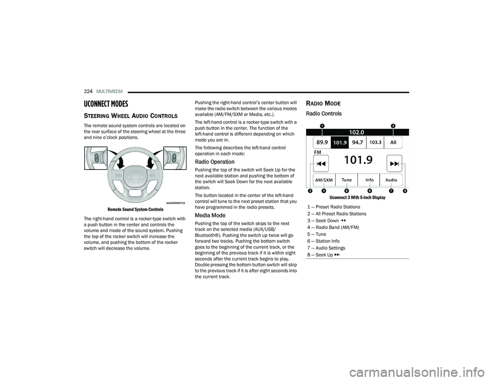
Radio Controls
Uconnect 3 With 5-inch Display
1 — Preset Radio Stations
2 — All Preset Radio Stations
3 — Seek Down
4 — Radio Band (AM/FM)
5 — Tune
6 — Station Info
7 — Audio Settings
8 — Seek Up
23_DPF_OM_EN_USC_t.book Page 224