display RAM CHASSIS CAB 2023 Owners Manual
[x] Cancel search | Manufacturer: RAM, Model Year: 2023, Model line: CHASSIS CAB, Model: RAM CHASSIS CAB 2023Pages: 444, PDF Size: 20.51 MB
Page 6 of 444
4
GETTING TO KNOW YOUR
INSTRUMENT PANEL
MIDLINE INSTRUMENT CLUSTER — GASOLINE.....78
Midline Instrument Cluster Descriptions ........79
HIGHLINE INSTRUMENT CLUSTER — GASOLINE...80
Highline Instrument Cluster Descriptions.......81
PREMIUM INSTRUMENT CLUSTER — GASOLINE ..82
Premium Instrument Cluster Descriptions —
Gasoline ............................................................83
BASE INSTRUMENT CLUSTER — DIESEL ........... 84
Diesel Instrument Cluster ...............................85
MIDLINE INSTRUMENT CLUSTER — DIESEL ...... 86
Diesel Instrument Cluster ...............................87
PREMIUM INSTRUMENT CLUSTER — DIESEL .... 88
Premium Instrument Cluster Descriptions —
Diesel ................................................................89
INSTRUMENT CLUSTER DISPLAY ........................ 89
Instrument Cluster Display Location and
Controls .............................................................90
Oil Life Reset ....................................................92
Display Menu Items .........................................93
Diesel Messages And Warnings ......................98
Battery Saver On/Battery Saver Mode
Message — Electrical Load Reduction
Actions — If Equipped ................................... 101 WARNING LIGHTS AND MESSAGES ................. 102
Red Warning Lights ....................................... 103
Yellow Warning Lights ................................... 105Yellow Indicator Lights .................................. 108
Green Indicator Lights .................................. 109
White Indicator Lights ................................... 110Blue Indicator Lights ..................................... 111
ONBOARD DIAGNOSTIC SYSTEM — OBD II ..... 111
Onboard Diagnostic System
(OBD II) Cybersecurity ................................... 111
EMISSIONS INSPECTION AND MAINTENANCE
PROGRAMS.......................................................... 112
STARTING AND OPERATING
STARTING THE ENGINE— GASOLINE ENGINE.. 113
Automatic Transmission ............................... 113
AutoPark — Rotary Shifter and 8-Speed
Transmission Only ......................................... 113
Tip Start Feature .......................................... 115
Keyless Enter ‘n Go™ — Ignition................... 115Normal Starting Using ENGINE START/STOP
Button ........................................................... 115
Cold Weather Operation
(Below –22°F Or −30°C) ............................ 117
After Starting ................................................. 117 STARTING THE ENGINE — DIESEL ENGINE....... 117
Automatic Transmission ............................... 117
Keyless Enter ‘n Go™ — Ignition .................. 117
Extreme Cold Weather .................................. 119Normal Starting Procedure — Engine Manifold
Air Temperature Above 66°F (19°C) .......... 119
Starting Procedure — Engine Manifold
Air Temperature 0°F To 66°F
(–18°C to 19°C) ........................................... 120
Starting Procedure — Engine Manifold Air
Temperature Below 0°F (-18°C) ................. 121
Starting Fluids ............................................... 121
NORMAL OPERATION — DIESEL ENGINE ......... 122
Cold Weather Precautions ............................ 122
Engine Idling ................................................. 124
Noise .............................................................. 124
Stopping The Engine ..................................... 125Idle Shutdown ............................................... 125Programmable Maximum Vehicle Speed .... 126
Operating Precautions .................................. 126Cooling System Tips ...................................... 126
Diesel Particulate Filter (DPF) Manual
Regeneration — If Equipped ......................... 127
ENGINE BLOCK HEATER — IF EQUIPPED .......... 127
ENGINE BREAK-IN RECOMMENDATIONS—
GASOLINE ENGINE .............................................. 127
23_DPF_OM_EN_USC_t.book Page 4
Page 7 of 444
5
ENGINE BREAK-IN RECOMMENDATIONS —
DIESEL ENGINE .................................................... 128
PARKING BRAKE ................................................ 128
DIESEL EXHAUST BRAKE (ENGINE BRAKING) .. 129
AUTOMATIC TRANSMISSION.............................. 130 Ignition Park Interlock ................................... 131Brake/Transmission Shift Interlock (BTSI)
System .......................................................... 131
8-Speed Automatic Transmission —
If Equipped .................................................... 132
6-Speed Automatic Transmission —
If Equipped .................................................... 135
AUXILIARY SWITCHES — IF EQUIPPED ............. 139
FOUR-WHEEL DRIVE OPERATION —
IF EQUIPPED ........................................................ 140
Electronically Shifted Transfer Case
(8-Speed Transmission) — If Equipped ....... 140Electronically Shifted Transfer Case
(6-Speed Transmission) —
If Equipped..................................................... 143
Manually Shifted Transfer Case —
If Equipped..................................................... 145
LIMITED-SLIP DIFFERENTIAL ............................ 147
POWER TAKE OFF (PTO) OPERATION —
IF EQUIPPED ........................................................ 147
HYDRAULIC POWER STEERING .........................148
Power Steering Fluid Check .......................... 148
CRUISE CONTROL SYSTEMS — IF EQUIPPED .... 148
Cruise Control ............................................... 149
Adaptive Cruise Control (ACC) ...................... 150 PARKSENSE FRONT/REAR PARK ASSIST —
IF EQUIPPED ....................................................... 159
ParkSense Sensors ....................................... 159
ParkSense Warning Display ......................... 159
ParkSense Display ........................................ 159Enabling And Disabling ParkSense .............. 162
Service The ParkSense Park Assist System ...162
Cleaning The ParkSense System ................. 162
ParkSense System Usage Precautions........ 162
LANESENSE — IF EQUIPPED ............................. 163
LaneSense Operation ................................... 163Turning LaneSense On Or Off ....................... 164
LaneSense Warning Message ...................... 164Changing LaneSense Status ........................ 166
Turn Signal Activated Blind Spot Assist —
If Equipped..................................................... 166
PARKVIEW REAR BACK UP CAMERA............... 166
SURROUND VIEW CAMERA SYSTEM —
IF EQUIPPED ........................................................ 168
TRAILER CAMERAS — IF EQUIPPED ................. 173 Trailer Surround View Camera System —
If Equipped..................................................... 173AUX Camera — If Equipped ........................... 176
ENGINE RUNAWAY ............................................. 176
REFUELING THE VEHICLE—
GASOLINE ENGINE ............................................. 177
Loose Fuel Filler Cap Message ................... 177
REFUELING THE VEHICLE — DIESEL ENGINE... 177
Diesel Exhaust Fluid...................................... 178 VEHICLE LOADING .............................................. 180
Gross Vehicle Weight Rating (GVWR) ......... 180
Payload .......................................................... 180Gross Axle Weight Rating (GAWR)................ 180Tire Size ......................................................... 181
Rim Size ......................................................... 181
Inflation Pressure .......................................... 181Curb Weight ................................................... 181
Loading .......................................................... 181
TRAILER TOWING ................................................ 181
Common Towing Definitions......................... 181
Trailer Hitch Type and Maximum Trailer
Weight ............................................................ 185
Trailer Towing Weights (Maximum Traile
r Weight Ratings) .......................................... 186Trailer And Tongue Weight .......................... 186
Towing Requirements .................................. 186Towing Tips ................................................... 192
SNOWPLOW — IF EQUIPPED.............................. 192
Before Plowing .............................................. 192
Snowplow Prep Package Model Availability....193
Over The Road Operation With Snowplow
Attached......................................................... 193
Operating Tips ............................................... 193General Maintenance ................................... 193
23_DPF_OM_EN_USC_t.book Page 5
Page 16 of 444

14 Green Indicator Lights
Adaptive Cruise Control (ACC) Set With Target Indicator Light Úpage 109
Adaptive Cruise Control (ACC) Set With No Target Detected Indicator Light
Ú page 110
Automatic Diesel Exhaust Brake Indicator Light Úpage 110
Cruise Control Set Indicator Light Úpage 110
ECO Mode Indicator Light Úpage 110
Front Fog Indicator Light Úpage 110
LaneSense Indicator Light Úpage 110
Parking/Headlights On Indicator Light Úpage 110
Turn Signal Indicator Lights
Úpage 110
White Indicator Lights
Adaptive Cruise Control (ACC) Ready Indicator Light Úpage 110
Cruise Control Ready Indicator Light Úpage 110
LaneSense Indicator Light Úpage 110
Set Speed Display Indicator Light Úpage 110
Blue Indicator Lights High Beam Indicator Light Úpage 111
Green Indicator Lights
23_DPF_OM_EN_USC_t.book Page 14
Page 17 of 444
15
GETTING TO KNOW YOUR VEHICLE
KEYS
KEY FOB
Your vehicle is equipped with a key fob which
supports Remote Keyless Entry (RKE) (if equipped)
and Keyless Enter ‘n Go™ (if equipped).
If the vehicle is equipped with remote power door
locks, the key fob allows you to lock or unlock all
doors, as well as activate the Panic Alarm, from
distances up to approximately 66 ft (20 m). The
key fob does not need to be pointed at the vehicle
to activate the system.
NOTE:
The key fob’s wireless signal may be blocked if
the key fob is located next to a mobile phone,
laptop, or other electronic device. This may
result in poor performance.
The key fob should not be placed next to the
wireless charging pad (if equipped).
In the ON/RUN position, all key fob buttons will
work until the vehicle reaches 2 mph (4 km/h).
Key Fob
In case the ignition switch does not change with
the push of a button, the key fob may have a low or
fully depleted battery. A low key fob battery can be
verified by referring to the instrument cluster,
which will display directions to follow
Úpage 427.
To Lock/Unlock The Doors
If the vehicle is equipped with remote power door
locks, push and release the unlock button on the
key fob once to unlock the driver’s door. Push the
unlock button twice within five seconds to unlock
all doors. If the vehicle is equipped with remote
power door locks, push and release the lock button
on the key fob to lock all doors.
When the doors are unlocked, the turn signals will
flash and the Illuminated Entry system will be
activated. When the doors are locked, the turn
signals will flash and the horn will chirp.
All doors can be programmed to unlock on the first
push of the unlock button. The horn chirp when the
lock button is pushed can be programmed on/off
within Uconnect Settings Ú page 199.
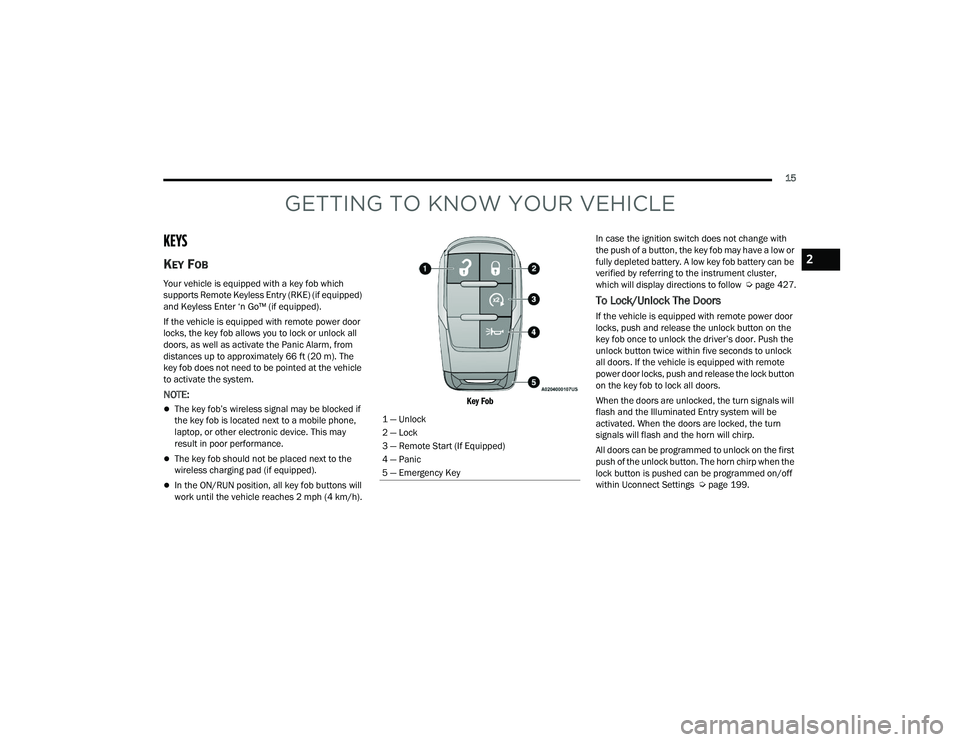
1 — Unlock
2 — Lock
3 — Remote Start (If Equipped)
4 — Panic
5 — Emergency Key
2
23_DPF_OM_EN_USC_t.book Page 15
Page 18 of 444

16GETTING TO KNOW YOUR VEHICLE
Using The Panic Feature
To turn the Panic feature on or off, push the Panic
button on the key fob. When the Panic feature is
activated, the turn signals will flash, the horn may
pulse on and off (if equipped with horn alarm), and
the interior lights will turn on.
The Panic feature will stay on for three minutes
unless you turn it off by either pushing the Panic
button a second time or driving the vehicle at a
speed of 15 mph (24 km/h) or greater.
NOTE:
The interior lights will turn off if you place the
ignition in the ON/RUN position while the Panic
feature is activated. However, the exterior lights
and horn (if equipped with horn alarm) will
remain on.
You may need to be less than 35 ft (11 m) from
the vehicle when using the key fob to turn off the
Panic feature due to the radio frequency noises
emitted by the system.
Key Left Vehicle Feature
If a valid key fob is no longer detected inside the
vehicle while the vehicle’s ignition system is in the
ON/RUN or START position, the message “Key Fob
Has Left The Vehicle” will be shown in the
instrument cluster display along with an interior
chime. An exterior audible and visual alert will also
be activated to warn the driver. The vehicle’s horn will rapidly chirp three times
along with a single flash of the vehicle’s exterior
lights.
NOTE:
The doors have to be open and then closed in
order for the vehicle to detect a key fob; the Key
Left Vehicle feature will not activate until all of
the doors are closed.
These alerts will not be activated in situations
where the vehicle’s engine is left running with
the key fob inside.
Replacing The Battery In The Key Fob
The replacement battery model is one CR2032
battery.
NOTE:
Customers are recommended to use a battery
obtained from Mopar®. Aftermarket coin
battery dimensions may not meet the original
OEM coin battery dimensions.
Perchlorate Material — special handling may
apply. See www.dtsc.ca.gov/hazard
-
ouswaste/perchlorate for further information.
Do not touch the battery terminals that are on
the back housing or the printed circuit board.
1. Remove the emergency key (1) by pushing
and holding the release button (2) located on
the side of the key fob while pulling the
emergency key out with your other hand.
Emergency Key Removal
2. Hold the key fob with the button side facing down, and locate the small rectangular gap on
the left side between the housing and the back
cover of the key fob. Use a small screwdriver
(or similar tool) to pry open the left side of the
fob cover while applying pressure until the
cover snaps open.
1 — Emergency Key
2 — Emergency Key Release Button
23_DPF_OM_EN_USC_t.book Page 16
Page 23 of 444

GETTING TO KNOW YOUR VEHICLE21
Vehicle Security system not active
Malfunction Indicator Light (MIL) is not illumi -
nated
TO EXIT REMOTE START MODE
To drive the vehicle after starting the Remote Start
system, push and release the START/STOP ignition
button while pressing the brake pedal prior to the
end of the 15 minute cycle.
The Remote Start system will turn the engine off if
the Remote Start button on the key fob is pushed
again, or if the engine is allowed to run for the
entire 15 minute cycle. Once the ignition is placed
in the ON/RUN position, the climate controls will
resume the previously set operations
(temperature, blower control, etc.).
NOTE:
For vehicles equipped with the Keyless
Enter ‘n Go™ — Passive Entry feature, the
message “Remote Start Active — Push Start
Button” will display in the instrument cluster
display until you push the START/STOP ignition
button.
To avoid unintentional shutdowns, the system
will disable for two seconds after receiving a
valid Remote Start request.
REMOTE START FRONT DEFROST
A
CTIVATION — IF EQUIPPED
When Remote Start is active, and the outside
ambient temperature is 40°F (4.5°C) or below, the
system will automatically activate front defrost for
15 minutes or less. The time is dependent on the
ambient temperature. Once the timer expires, the
system will automatically adjust the settings
depending on ambient conditions. See “Remote
Start Comfort Systems — If Equipped” in the next
section for detailed operation.
REMOTE START COMFORT SYSTEMS —
I
F EQUIPPED
When Remote Start is activated, the front and rear
defrost will automatically turn on in cold weather.
The heated steering wheel and driver heated seat
feature will turn on if programmed in the Comfort
menu screen within Uconnect Settings
Ú page 199. In warm weather, the driver vented
seat feature will automatically turn on when
Remote Start is activated, if programmed in the
Comfort menu screen. The vehicle will adjust the
climate control settings depending on the outside
ambient temperature. Automatic Temperature Control (ATC) —
If Equipped
The climate controls automatically adjust to an
optimal temperature and mode, dependent on the
outside ambient temperature. When the ignition is
placed in the ON/RUN position, the climate
controls will resume their previous settings.
Manual Temperature Control (MTC) — If Equipped
In ambient temperatures of 40°F (4.5°C) or
below, the climate settings will default to
maximum heat, with fresh air entering the
cabin. If the front defrost timer expires, the
vehicle will enter Mix Mode.
In ambient temperatures from 40°F (4.5°C) to
78°F (26°C), the climate settings will be based
on the last settings selected by the driver.
In ambient temperatures of 78°F (26°C) or
above, the climate settings will default to MAX
A/C, Bi-Level mode, with Recirculation on.
For more information on ATC, MTC, and climate
control settings, see Ú page 58.
NOTE:These features will stay on through the duration of
Remote Start, or until the ignition is placed in the
ON/RUN position. The climate control settings will
change, and exit the automatic defaults, if
manually adjusted by the driver while the vehicle is
in Remote Start mode. This includes turning the
climate controls off using the OFF button.
2
23_DPF_OM_EN_USC_t.book Page 21
Page 24 of 444

22GETTING TO KNOW YOUR VEHICLE
(Continued)
REMOTE START WINDSHIELD WIPER
D
E-ICER ACTIVATION — IF EQUIPPED
When Remote Start is active and the outside
ambient temperature is less than 33°F (0.6°C),
the Windshield Wiper De-Icer will activate. Exiting
Remote Start will resume its previous operation. If
the Windshield Wiper De-Icer was active, the timer
and operation will continue.
REMOTE START ABORT MESSAGE
One of the following messages will display in the
instrument cluster display if the vehicle fails to
remote start or exits Remote Start prematurely:
Remote Start Canceled — Door Open
Remote Start Canceled — Hood Open
Remote Start Canceled — Fuel Low
Remote Start Canceled — System Fault
Remote Start Disabled — Start Vehicle to Reset
The instrument cluster display message stays
active until the ignition is placed in the ON/RUN
position.
REMOTE START — IF EQUIPPED (DIESEL)
This system uses the key fob to start the
engine conveniently from outside the
vehicle while still maintaining security. The system has a range of approximately 300 ft
(91 m).
Remote Start is used to defrost windows in cold
weather, and to reach a comfortable climate in all
ambient conditions before the driver enters the
vehicle.
NOTE:
Obstructions between the vehicle and the key
fob may reduce this range.
The Remote Start system will wait for the Wait
To Start Light
Úpage 109 to extinguish before
cranking the engine. This allows time for the
intake heater to preheat the incoming air, and is
normal operation in cold weather Ú page 427.
HOW TO USE REMOTE START
Push and release the Remote Start button on the
key fob twice within five seconds. The vehicle
doors will lock, the parking lights will flash, and the
horn will chirp twice (if programmed). Then, the
engine will start, and the vehicle will remain in the
Remote Start mode for a 15 minute cycle.
Pushing the Remote Start button a third time shuts
the engine off.
To drive the vehicle, push the unlock button, and
place the ignition in the ON/RUN position. All of the following conditions must be met before
the engine will remote start:
Gear selector in PARK
Doors closed
Hood closed
Hazard switch off
Brake switch inactive (brake pedal not pressed)
Battery at an acceptable charge level
Panic button not pushed
Fuel meets minimum requirement
Water In Fuel Indicator Light is not illuminated
Wait To Start Light is not illuminated
Malfunction Indicator Light (MIL) is not illumi
-
nated
For additional functions of the Remote Start
system, see Ú page 21.
WARNING!
Do not start or run an engine in a closed
garage or confined area. Exhaust gas contains
carbon monoxide (CO) which is odorless and
colorless. Carbon monoxide is poisonous and
can cause serious injury or death when
inhaled.
23_DPF_OM_EN_USC_t.book Page 22
Page 28 of 444

26GETTING TO KNOW YOUR VEHICLE
Preventing Inadvertent Locking Of Passive Entry
Key Fob In Vehicle:
To minimize the possibility of unintentionally
locking a Passive Entry key fob inside your vehicle,
the Passive Entry system is equipped with an
automatic door unlock feature which will function if
the ignition switch is in the OFF position.
If one of the vehicle doors is open and the door
panel switch is used to lock the vehicle, once all
open doors have been closed the vehicle checks
the inside and outside of the vehicle for any valid
Passive Entry key fobs. If one of the vehicle's
Passive Entry key fobs is detected inside the
vehicle, and no other valid Passive Entry key fobs
are detected outside the vehicle, the Passive Entry
system automatically unlocks all vehicle doors and
chirps the horn three times (on the third attempt
ALL doors will lock and the Passive Entry key fob
can be locked in the vehicle).
To Lock The Vehicle’s Doors:
With one of the vehicle’s Passive Entry key fobs
within 5 ft (1.5 m) of the driver or passenger front
door handles, push the door handle lock button to
lock all doors.
Push The Door Handle Button To Lock
Do NOT grab the door handle when pushing the
door handle lock button. This could unlock the
door(s).
Do NOT Grab The Door Handle When Locking
NOTE:
After pushing the door handle lock button, you
must wait two seconds before you can lock or
unlock the doors, using either Passive Entry
door handle. This is done to allow you to check
if the vehicle is locked by pulling the door
handle, without the vehicle unlocking.
The Passive Entry system depends on a key fob
that is not fully discharged of its coin battery
capacity.
When the key fob battery is low, the instrument
cluster will display a message indicating that the
key fob battery is low Ú page 15.
The vehicle doors can also be locked by using the
key fob lock button or the lock button located on
the vehicle’s interior door panel Ú page 427.
AUTOMATIC UNLOCK DOORS ON EXIT —
I
F EQUIPPED
The doors will unlock automatically on vehicles
with power door locks after the following sequence
of actions:
1. The Automatic Unlock Doors On Exit feature is
enabled.
2. All doors are closed.
3. The gear selector was not in PARK, then is placed in PARK.
4. Any door is opened.
23_DPF_OM_EN_USC_t.book Page 26
Page 30 of 444
28GETTING TO KNOW YOUR VEHICLE
HEATED STEERING WHEEL —
I
F EQUIPPED
The steering wheel contains a heating
element that helps warm your hands in
cold weather. The heated steering wheel
has only one temperature setting. Once
the heated steering wheel has been turned on, it
will stay on until the operator turns it off. The
heated steering wheel may not turn on when it is
already warm.
The heated steering wheel button is located on the
center of the instrument panel below the radio
screen, or within the climate or comfort screen of
the touchscreen.
NOTE:If the vehicle is equipped with a 12-inch radio,
there will only be control buttons through the
touchscreen.
Press the heated steering wheel button once to
turn the heating element on.
Press the heated steering wheel button a
second time to turn the heating element off.
NOTE:The engine must be running for the heated
steering wheel to operate.
For information on use with the Remote Start
system, see Ú page 21.
UCONNECT VOICE RECOGNITION —
IF EQUIPPED
INTRODUCING VOICE RECOGNITION
Start using Uconnect Voice Recognition with these
helpful quick tips. It provides the key Voice
Commands and tips you need to know to control
your vehicle’s Voice Recognition (VR) system.
Uconnect 3 With 5-inch Display
If you see the NAV icon on the bottom bar or in the
Apps menus of your 8.4-inch touchscreen, you
have the Uconnect 5 NAV system. If not, you have
a Uconnect 5 with 8.4-inch display system.
WARNING!
Do not adjust the steering column while driving.
Adjusting the steering column while driving or
driving with the steering column unlocked, could
cause the driver to lose control of the vehicle.
Failure to follow this warning may result in
serious injury or death.
WARNING!
Persons who are unable to feel pain to the
skin because of advanced age, chronic illness,
diabetes, spinal cord injury, medication,
alcohol use, exhaustion, or other physical
conditions must exercise care when using the
steering wheel heater. It may cause burns
even at low temperatures, especially if used
for long periods.
Do not place anything on the steering wheel
that insulates against heat, such as a blanket
or steering wheel covers of any type or mate -
rial. This may cause the steering wheel heater
to overheat.
23_DPF_OM_EN_USC_t.book Page 28
Page 32 of 444
30GETTING TO KNOW YOUR VEHICLE
ADDITIONAL INFORMATION
© 2022 FCA US LLC. All rights reserved. Mopar and
Uconnect are registered trademarks and Mopar
Owner Connect is a trademark of FCA US LLC.
SiriusXM® and all related marks and logos are
trademarks of SiriusXM® Radio Inc.
Uconnect System Support:
US residents visit www.DriveUconnect.com or
call: 1-877-855-8400 (24 hours a day 7 days a
week)
Canadian residents visit www.DriveUcon -
nect.ca or call: 1-800-465-2001 (English) or
1-800-387-9983 (French)
SiriusXM Guardian™ services support:
US residents visit www.driveuconnect.com/
sirius-xm-guardian or call: 1-844-796-4827
Canadian residents visit https://www.driveu -
connect.ca/en/sirius-xm-guardian or call:
1-877-324-9091
DRIVER MEMORY SETTINGS — IF EQUIPPED
This feature allows the driver to save up to two
different memory profiles for easy recall through a
memory switch. Each memory profile saves
desired position settings for the following features:
Driver seat position
Easy Entry/Exit seat operation (if equipped)
Side mirrors
Adjustable pedals (if equipped)
A set of desired radio station presets
NOTE:
If equipped with power convex mirrors, these
mirror positions will not set as part of a memory
profile.
Your vehicle is equipped with two key fobs, each
can be linked to either memory position 1 or 2.
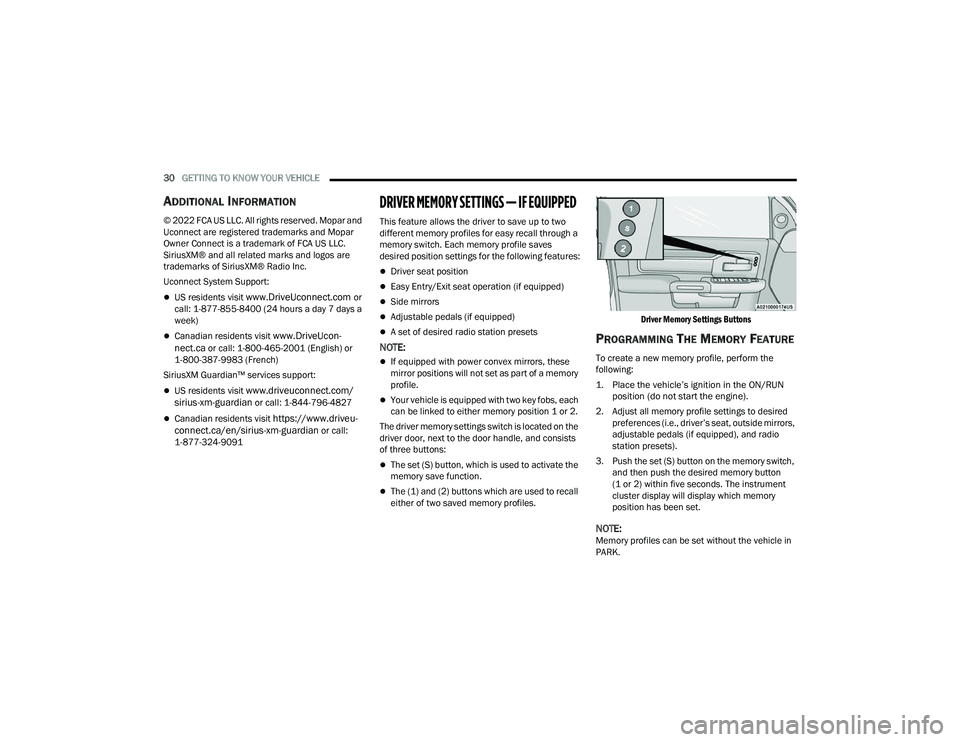
The driver memory settings switch is located on the
driver door, next to the door handle, and consists
of three buttons:
The set (S) button, which is used to activate the
memory save function.
The (1) and (2) buttons which are used to recall
either of two saved memory profiles.
Driver Memory Settings Buttons
PROGRAMMING THE MEMORY FEATURE
To create a new memory profile, perform the
following:
1. Place the vehicle’s ignition in the ON/RUN
position (do not start the engine).
2. Adjust all memory profile settings to desired preferences (i.e., driver’s seat, outside mirrors,
adjustable pedals (if equipped), and radio
station presets).
3. Push the set (S) button on the memory switch, and then push the desired memory button
(1 or 2) within five seconds. The instrument
cluster display will display which memory
position has been set.
NOTE:Memory profiles can be set without the vehicle in
PARK.
23_DPF_OM_EN_USC_t.book Page 30